

KUBOTA Loader LA271 LA301 LA351 LA401 Workshop Service Manual
What's Included?
Fast Download Speeds
Online & Offline Access
Access PDF Contents & Bookmarks
Full Search Facility
Print one or all pages of your manual
SAFETY INSTRUCTIONS LA271 • LA301 • LA351 • LA401 WSM. 17020
A SAFETY FIRST
This symbol, the industry's "Safety Alert Symbol" I is used throughout this manual and decals on
the machine Itself to warn of the possibility of personal injury. Read these instructions carefully.
It is essential that you read the instructions and safety regulations before you attempt to repair or
use this unit.
A DANGER : Indicates an imminently hazardous situation which, if not avoided, will result In death
or serious Injury.
A WARNING: Indicates a potentially hazardous situation which, if not avoided, could result in death
or serious injury.
A CAUTION : Indicates a potentially hazardous situation which, if not avoided, may result in minor
or moderate injury.
• IMPORTANT : Indicates that equipment or property damage could result if instructions are not
followed.
: Gives helpful information.
I_NOTE
I
OOOOOZOOO10
00000F00010
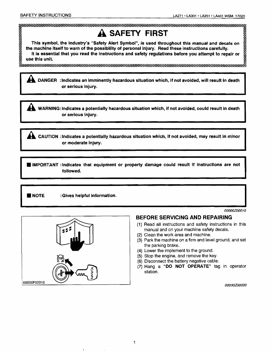
BEFORE SERVICING AND REPAIRING
(1) Read all instructions and safety instructions in this
manual and on your machine safety decals.
(2) Clean the work area and machine.
(3) Park the machine on a firm and level ground, and set
the parking brake.
(4) Lower the implement to the ground.
(5) Stop the engine, and remove the key.
(6) Disconnect the battery negative cable.
(7) Hang a "DO NOT OPERATE" tag in operator
station.
OOOOOZOO020
lA271 • LA301 • LA351 • LA401 WSM, 17020
SAFETY INSTRUCTIONS
OOOOOFOOO20
OOOOOFOO030
OOOOOFOO050
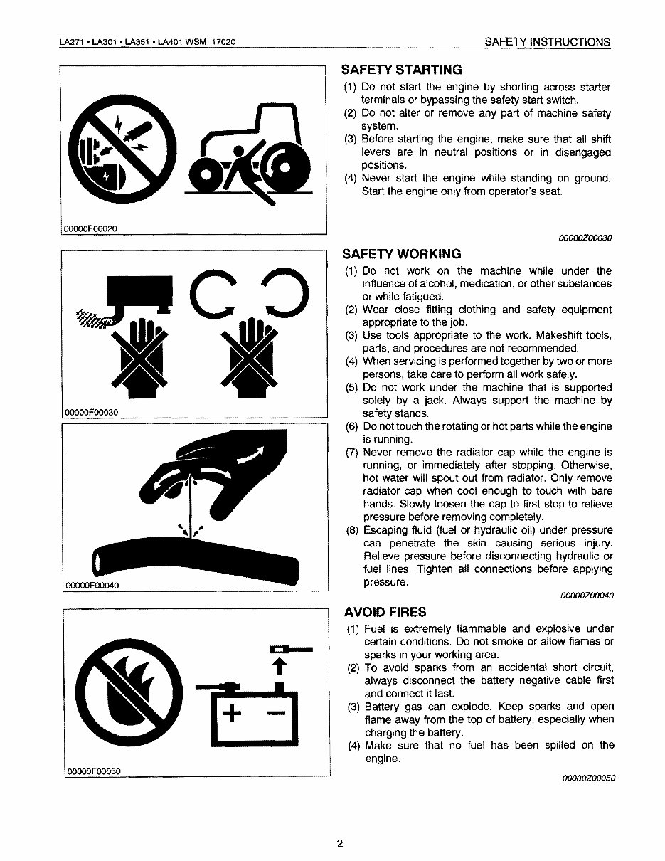
SAFETY STARTING
(1) Do not start the engine by shorting across starter
terminals or bypassing the safety start switch.
(2) Do not alter or remove any part of machine safety
system.
(3) Before starting the engine, make sure that all shift
levers are in neutral positions or in disengaged
positions.
(4) Never start the engine while standing on ground.
Start the engine only from operator's seat.
00000Z00030
SAFETY WORKING
(1) Do not work on the machine while under the
influence of alcohol, medication, or other substances
or while fatigued.
(2) Wear close fitting clothing and safety equipment
appropriate to the job.
(3) Use tools appropriate to the work. Makeshift tools,
parts, and procedures are not recommended.
(4) When servicing is performed together by two or more
persons, take care to perform all work safely.
(5) Do not work under the machine that is supported
solely by a jack. Always support the machine by
safety stands.
(6) Do not touch the rotating or hot parts while the engine
is running.
(7) Never remove the radiator cap while the engine is
running, or immediately after stopping. Otherwise,
hot water will spout out from radiator. Only remove
radiator cap when cool enough to touch with bare
hands. Slowly loosen the cap to first stop to relieve
pressure before removing completely.
(8) Escaping fluid (fuel or hydraulic oil) under pressure
can penetrate the skin causing serious injury.
Relieve pressure before disconnecting hydraulic or
fuel lines. Tighten all connections before applying
pressure.
00000Zoo040
AVOID FIRES
(1) Fuel is extremely flammable and explosive under
certain conditions. Do not smoke or allow flames or
•
+
-
sparks in your working area.
(2) To avoid sparks from an accidental short circuit,
always disconnect the battery negative cable first
and connect it last.
(3) Battery gas can explode. Keep sparks and open
flame away from the top of battery, especially when
charging the battery.
(4) Make sure that no fuel has been spilled on the
engine.
00000Z00050
2
SAFETY INSTRUCTIONS 1..A271 • LA301 • LA351 • LA401 WSM. 17020
OOOOOFOO090
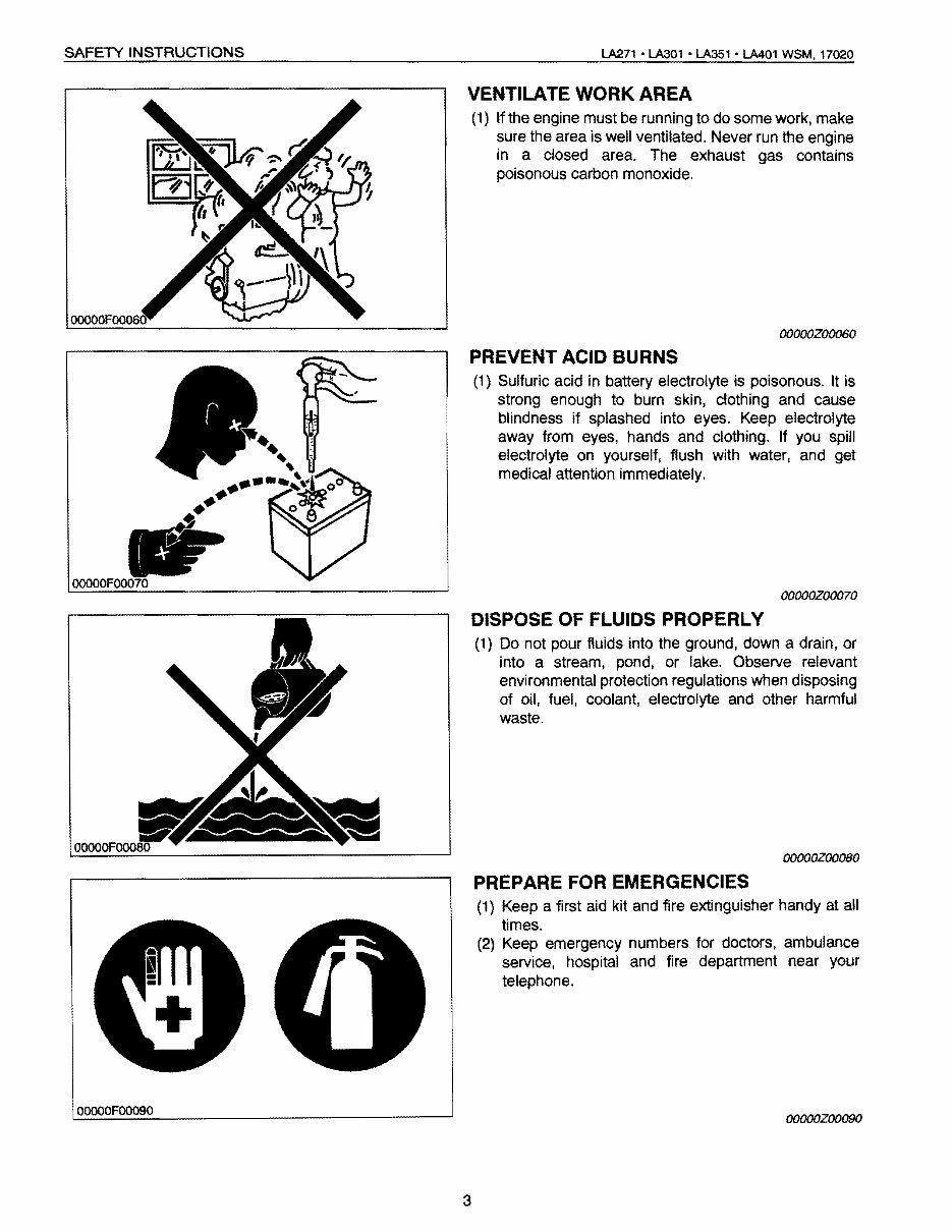
VENTILATE WORK AREA
(1) If the engine must be running to do some work, make
sure the area is well ventilated. Never run the engine
in a closed area. The exhaust gas contains
poisonous carbon monoxide.
OOOOOZ00060
PREVENT ACID BURNS
(1) Sulfuric acid in battery electrolyte is poisonous. It is
strong enough to burn skin, clothing and cause
blindness if splashed into eyes. Keep electrolyte
away from eyes, hands and clothing. If you spill
electrolyte on yourself, flush with water, and get
medical attention immediately.
OOOOOZOOO70
DISPOSE OF FLUIDS PROPERLY
(1) Do not pour fluids into the ground, down a drain, or
into a stream, pond, or lake. Observe relevant
environmental protection regulations when disposing
of oil. fuel. coolant. electrolyte and other harmful
waste.
OOOOOZOO080
PREPARE FOR EMERGENCIES
(1) Keep a first aid kit and fire extinguisher handy at all
times.
(2) Keep emergency numbers for doctors, ambulance
service. hospital and fire department near your
telephone.
OOOOOZOO090
3
lA271 -lA301 -LA351 -LA401 WSM, 17020 SAFETY INSTRUCTIONS
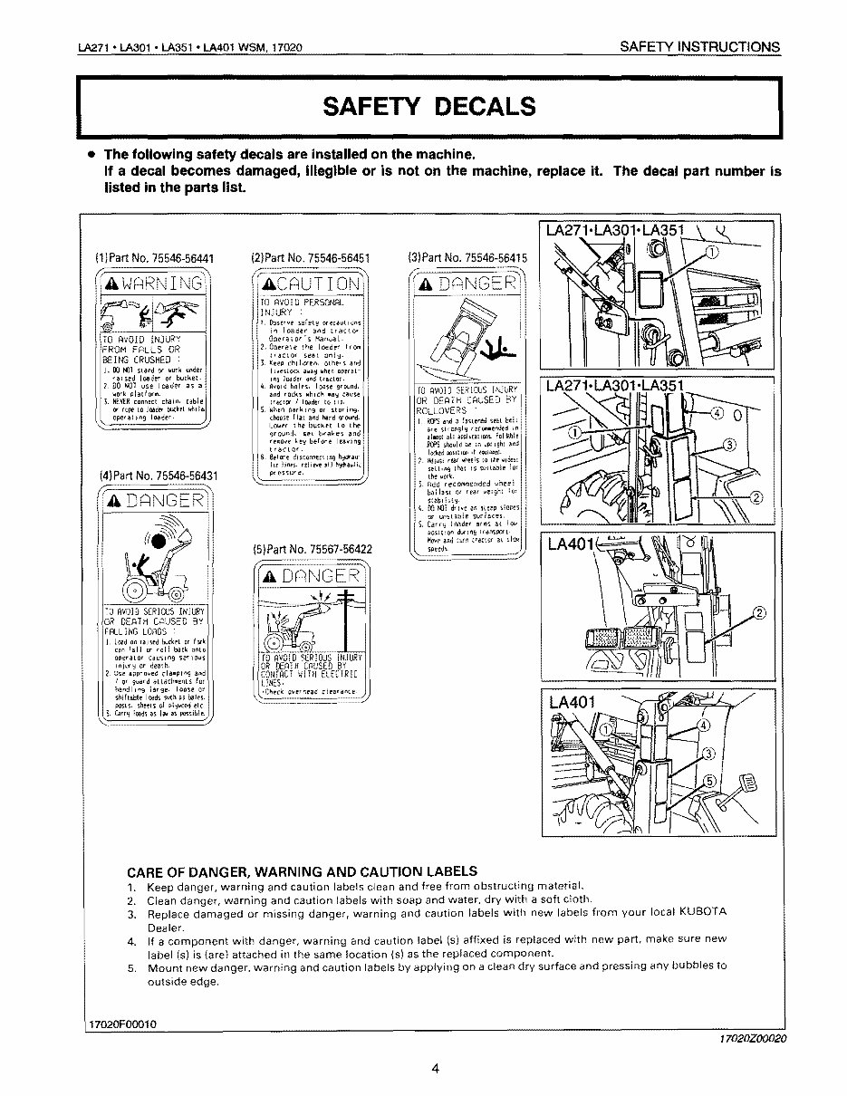
SAFETY DECALS
• The following safety decals are installed on the machine.
If a decal becomes damaged, Illegible or is not on the machine, replace it. The decal part number is
listed in the parts list.
(1 )Part No. 75546-56441
(AWARNING'
TO AVO! 0 !NJ URY
FROM FALLS OR
BEING CRUSHED ;
J. 00 t{l1 stand or work tJnder
r a I sed loader Of bucket,
1, DO NOT use I cade. as a
"'Oflo: pIaU arll.
NEVER connect chaIn. cable
r¥ rope 10 loader bucket whd4.
operat Ins loader,
(4)Part No. 75546-56431
(A DANGERI
TO AVOID SERIOUS INJURY
OR DEATH CAUSED BY
FALL I NG LOADS
L Load on raISed buckt'L or fork
can rail or rol! back onto-
operator causln9 ser IOUS
Injury or death.
l, Use 3;Jpro'yed clampln9 and
I Of Suard attachments fOf
handling lar'3e. looo;;e or
sniflable such as bales,
poSlS. sheets ot plY'tlooO etc·
Carr';! leeds as I!IV as: PGs'Slble,
(2)Part No. 75546-56451
ACAUTIONl
TO AVOID PERSONAL
INJURY :
I, Observe safety precaution'S
In leader and tractor
OCieralo,'s Manual·
2, ODe(ale the loader from
traCtor seat
3. Keep cnJldrel'l, others and
I t."enock ali3y when optrat-
1"9 loader and lraclor,
4. Avoid holes. loost ground.
and rocks which /lay cause
lraclcr I loader to tip.
S, 'When parking or storing.
choose rIal and hard gr OU'ld.
Lowtr the bucket to the
ground, set brakes and
rel'lO\ie ke\J before lea\iing
tractor.
6, Br(ore hydrau-
liC IIt'lts. relINe all '"Pauli,
pr essur e,
(5)Part No. 75567-56422
(3) Part No. 75546-56415
TO AVOID SERIOUS INJURY
OR DEAT H CAUSE D BY
ROLLovERS
L RCf'S and a fastened seat be!r
are recOfI"lIIIended In
allWlscall aP9lm:liOtlS rol:2ble
RefS shaulc be :0 IIpr I gilt and
IodiN j)JJ.ltIOtilf
Z. Adju\l rear whtels Hi the ViceS!
selling tr..at IS suitable for
the vork,
t Add recOtMlended wheel
ballut or rear lo.Ielghi for
s:taiH I It':!'
4. 00 NlT drive on slopes
or
S. Carry loader at \01.1
posH :00 dur lAg tranSPOrt,
Move and :torn tractor at slav
speeds,
CARE OF DANGER, WARNING AND CAUTION LABELS
1. Keep danger, warning and caution labels clean and free from obstructing material.
2. Clean danger, warning and caution labels with soap and water. dry with a soft cloth.
3. Replace damaged or missing danger, warning and caution labels with new labels from your local KUBOTA
Dealer.
4. If a component with danger, warning and caution label (5) affixed is replaced with new part, make sure new
label (s) is (are) attached in the same location (s) as the replaced component.
5. Mount new danger, warning and caution labels by applying on a clean dry surface and pressing any bubbles to
outside edge.
17020FOOO10
17020Z00020
4
TERMINOLOGY lA271 • LA301 • LA351 • LA401 WSM, 17020
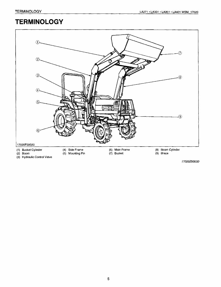
TERMINOLOGY
17020F00020
(1) Bucket Cylinder (4) Side Frame (6) Main Frame (8) Boom Cylinder
(2) Boom (5) Mounting Pin (7) Bucket (9) Brace
(3) Hydraulic Control Valve
17020Z00030
5
LA271 • LA301· LA351· LA401 WSM, 17020 SPECIFICATIONS
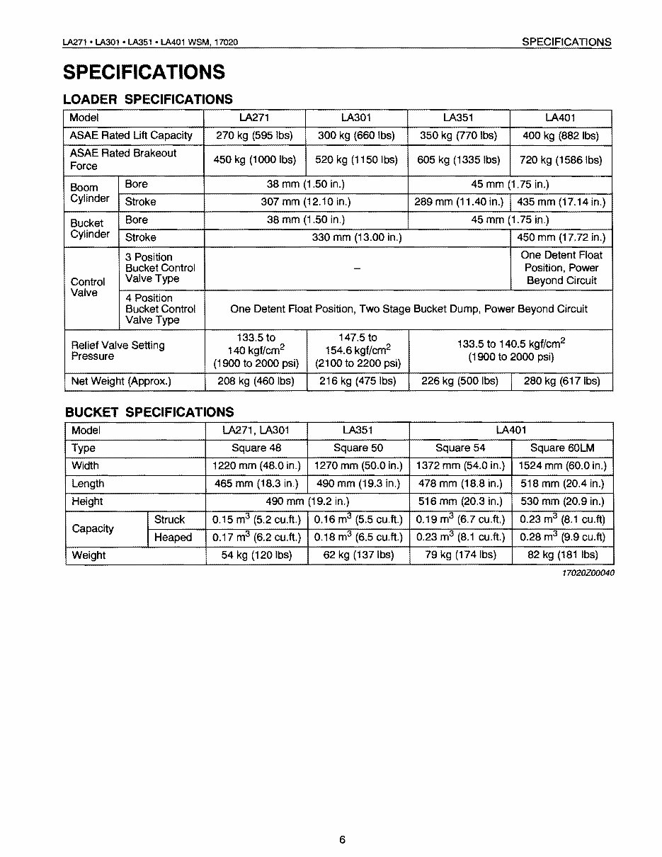
SPECIFICATIONS
LOADER SPECIFICATIONS
Model LA271 LA301 LA351 LA401
ASAE Rated Lift Capacity 270 kg (595 Ibs) 300 kg (660 Ibs) 350 kg (770 Ibs) 400 kg (882Ibs)
ASAE Rated Brakeout
Force
450 kg (1000 Ibs) 520 kg (1150 Ibs) 605 kg (1335 Ibs) 720 kg (1586 Ibs)
Boom
Cylinder
Bore 38 mm (1.50 in.) 45 mm (1.75 in.)
Stroke 307 mm (12.10 in.) 289 mm (11.40 in.) 435 mm (17.14 in.)
Bucket
Cylinder
Bore 38 mm (1.50 in.) 45 mm (1.75 in.)
Stroke 330 mm (13.00 in.) 450 mm (17.72 in.)
Control
Valve
3 Position
Bucket Control
Valve Type
-
One Detent Float
Position, Power
Beyond Circuit
4 Position
Bucket Control
Valve Type
One Detent Float Position, Two Stage Bucket Dump, Power Beyond Circuit
Relief Valve Setting
Pressure
133.5 to
140 kgf/cm
2
(1900 to 2000 psi)
147.5 to
154.6 kgf/cm
2
(2100 to 2200 psi)
133.5 to 140.5 kgf/cm
2
(1900 to 2000 psi)
Net Weight (Approx.) 208 kg (460 Ibs) 216 kg (475 Ibs) 226 kg (500 Ibs) 280 kg (617 Ibs)
BUCKET SPECIFICATIONS
Model LA271, LA301 LA351 LA401
Type Square 48 Square 50 Square 54 Square 60LM
Width 1220 mm (48.0 in.) 1270 mm (50.0 in.) 1372 mm (54.0 in.) 1524 mm (60.0 in.)
Length 465 mm (18.3 in.) 490 mm (19.3 in.) 478 mm (18.8 in.) 518 mm (20.4 in.)
Height 490 mm (19.2 in.) 516 mm (20.3 in.) 530 mm (20.9 in.)
Capacity
Struck 0.15 m
3
(5.2 cu.ft.) 0.16 m
3
(5.5 cu.ft.) 0.19 m
3
(6.7 cu.ft.) 0.23 m
3
(8.1 cu. ft)
Heaped 0.17 m
3
(6.2 cu.ft.) I 0.18 m
3
(6.5 cu.ft.) 0.23 m
3
(8.1 cu.ft.) 0.28 m
3
(9.9 cu.ft)
Weight 54 kg (120 Ibs)
I
62 kg (137Ibs) 79 kg (174Ibs) 82 kg (181 Ibs)
17020Z00040
6
I
DIMENSIONS lA271 • LA301 • LA351 • LA401 WSM, 17020
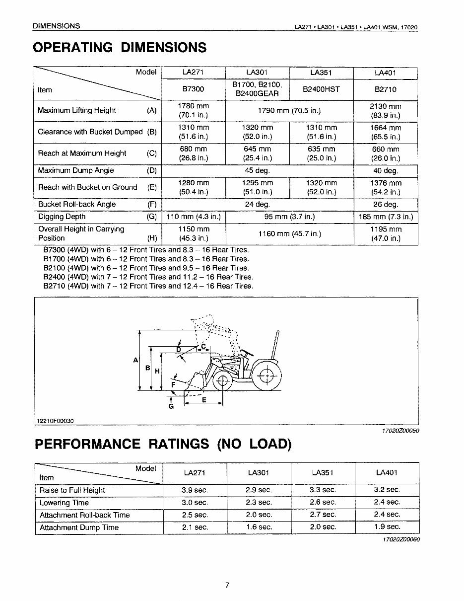
OPERATING DIMENSIONS
Item
LA271 LA301 LA351 LA401
B7300
B1700, B2100.
B2400GEAR
B2400HST B2710
i
Maximum Lifting Height (A)
1780 mm
(70.1 in.)
1790 mm (70.5 in.)
2130 mm
(83.9 in.)
Clearance with Bucket Dumped (B)
1310 mm
(51.6 in.)
1320 mm
(52.0 in.)
1310 mm
(51.6 in.)
1664 mm
(65.5 in.)
Reach at Maximum Height (C)
680mm
(26.8 in.)
645mm
(25.4 in.)
635mm
(25.0 in.)
660mm
(26.0 in.)
Maximum Dump Angle (D) 45 deg. 40 deg.
Reach with Bucket on Ground (E)
1280 mm
(50.4 in.)
1295 mm
(51.0 in.)
1320 mm
(52.0 in.)
1376 mm
(54.2 in.)
Bucket Roll-back Angle (F) 24 deg. 26 deg.
Digging Depth (G) 110 mm (4.3 in.) 95 mm (3,7 in.) 185 mm (7.3 in.)
Overall Height in Carrying
Position (H)
1150 mm
(45.3 in.)
1160 mm (45.7 in.)
1195 mm
(47.0 in.)
B7300 (4WD) with 6 12 Front Tires and 8.3 16 Rear Tires.
B1700 (4WD) with 6 12 Front Tires and 8.3 16 Rear Tires.
B2100 (4WD) with 6 12 Front Tires and 9.5 16 Rear Tires.
B2400 (4WD) with 7 - 12 Front Tires and 11.2 - 16 Rear Tires.
B271 0 (4WD) with 7 - 12 Front Tires and 12.4 - 16 Rear Tires.
A
B H
12210FOO030
17020Z00050
PERFORMANCE RATINGS {NO LOAD}
I
Item
LA271 LA301 LA351 LA401
Raise to Full Height 3.9 sec. 2.9 sec. 3.3 sec. 3.2 sec.
Lowering Time 3.0 sec. 2.3 sec. 2.6 sec. 2.4 sec.
Attachment Roll-back Time 2.5 sec. 2.0 sec. 2.7 sec. 2.4 sec.
Attachment Dump Time 2.1 sec. 1.6 sec. 2.0 sec. 1.9 sec.
17020Z00060
7
MECHANISM
CONTENTS
[1] FEATURES ...................................................................................................... M-1
[2] HYDRAULIC CIRCUIT .................................................................................... M-2
[3] CONTROL VALVE ASSEMBLY .................................................................... M·3
(1) LA271 • L.A301 • LA351 (Old Type Valve) .................................................. M-3
(2) LA271 • LA301 • LA351 (New Type Valve) and
LA401 (4 Position Bucket Control) ............................................................ M·11
(3) LA401 (3 Position Bucket ContrOl) ............................................................ M-19
[4] RELIEF VALVE ............................................................................................. M-23
[5] BOOM CYLINDER AND BUCKET CYLINDER ......................................... M-25

LA211 • LA301 • LA351 • LA401 WSM, 11020 MECHANISM
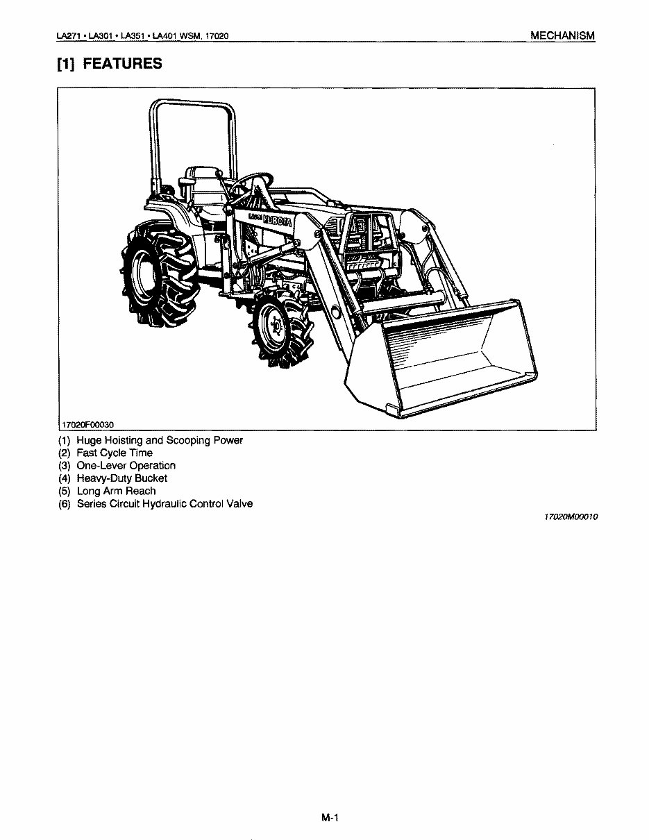
[1] FEATURES
11020F00030
(1) Huge HOisting and Scooping Power
(2) Fast Cycle Time
(3) One-Lever Operation
(4) Heavy-Duty Bucket
(5) Long Arm Reach
(6) Series Circuit Hydraulic Control Valve
17020MOOO10
M-1
You're Reading a Preview
What's Included?
Fast Download Speeds
Online & Offline Access
Access PDF Contents & Bookmarks
Full Search Facility
Print one or all pages of your manual
$31.99
Viewed 15 Times Today


Secure transaction
What's Included?
Fast Download Speeds
Online & Offline Access
Access PDF Contents & Bookmarks
Full Search Facility
Print one or all pages of your manual
$31.99
The Workshop Service Manual is a comprehensive guide offering detailed servicing instructions for your Kubota equipment. It provides complete step-by-step information on repair, servicing, preventative maintenance, and troubleshooting procedures. This manual features 55 pages with photos and illustrations, along with clear instructions to guide you through the entire repair process.
It is highly recommended to use Adobe Reader 9.0 or newer to view this manual. The current version of Adobe Reader can be accessed for free at get.adobe.com.
Whether you are a professional mechanic or a DIY enthusiast, this manual ensures satisfaction guaranteed!


