Cub Cadet RZT Zero Turn Rider Mower Service & Repair Manual
What's Included?
Lifetime Access
Fast Download Speeds
Online & Offline Access
Access PDF Contents & Bookmarks
Full Search Facility
Print one or all pages of your manual
Service Manual RZT Zero Turn Rider MTD Products Inc. - Product Training and Education Department FORM NUMBER - 769-01636 12/2004 NOTE: These materials are prepared for use by trained technicians who are experienced in the service and repair of equipment of the kind described in this publication, and are not intended for use by untrained or inexperienced individuals. Such individuals should seek the assistance of an authorized service technician or dealer. Read, understand, and follow all directions when working on this equip- ment. This includes the contents of the Operators Manual, which came with your equipment. No liability can be accepted for any inac- curacies or omission in this publication, although every care has been take to make it as complete and accurate as possible. The right is reserved to make changes at any time to this document without prior notice and without incurring an obligation to make such changes to previously published documents. All information contained in this publication is based on product information available at the time of publication. Photographs and illustrations used in this publication are for reference use only and may not depict actual model and component parts. www.mymowerparts.com K&T Saw Shop 606-678-9623 or 606-561-4983
www.mymowerparts.com K&T Saw Shop 606-678-9623 or 606-561-4983
Cub Cadet RZT Deck Leveling ............................................................................................................... 1 PTO / Deck Belt Replacement ...................................................................................... 2 Deck Removal ............................................................................................................... 2 Drive Belt Replacement ................................................................................................ 3 Servicing Electric PTO Clutch ....................................................................................... 3 Transmission Replacement .......................................................................................... 4 Steering Linkage: Adustment ........................................................................................ 6 Pivot Bar ....................................................................................................................... 9 Seat Removal ............................................................................................................. 10 Console Removal ........................................................................................................ 11 Battery Removal ......................................................................................................... 13 Fuel Tank Removal ..................................................................................................... 14 Control Shaft Replacement ......................................................................................... 15 Deck Lift Shaft Replacement ...................................................................................... 17 Electrical System Components ................................................................................... 20 TABLE OF CONTENTS www.mymowerparts.com K&T Saw Shop 606-678-9623 or 606-561-4983
www.mymowerparts.com K&T Saw Shop 606-678-9623 or 606-561-4983
1 617AA5A7P710 1D224G20073 2004 is the first year for the RZT. There are two mod- els RZT17 and RZT22. Now for the ‘05 model year is Kohler Command 19 HP model witha 50” deck. This series of riders has the unique feature of not hav- ing to reset the PTO switch if the end users tries to mow in reverse. Once one lapbar is moved in to neutral or forward the PTO will turn back on. The “RZT 17” has a 17 HP Briggs & Stratton Intek which is a single cylinder engine with full pressure lubri- cation. The engine drives the dual hydrogear EZT Hydrostatic transmissions and the electric PTO. The PTO runs the 3-in-1blades on the 42” twin blade stamped deck. On the front of the stamped frame is a large pivoting front axle. All this with the 3 gallon fuel tank will provide many hours of fun and relaxing mow- ing. The “RZT 22” is very similar to the RZT 17 except for the twin cylinder, 22 HP Briggs & Stratton Intek. There are also 4 wheels, instead of 2, on the 50” triple blade stamped deck. All versions of the Cub Cadet RZT (and White ZT) are bagger capable. 1. DECK LEVELING 1.1. To adjust the deck pitch, front to back, loosen or tighten the jam nuts located on the front stabi- lizer bracket using a 15/16” socket and a 15/16” wrench. The correct deck pitch should be 1/8” to 1/4” lower in the front than in the back, as mea- sured from the blade tips. See Figure 1.1. 1.2. To level the deck, side to side, loosen the screw on the left side adjustment gear using a 1/2” socket. Using a 3/4” wrench, run the gear up or down as necessary until each outside blade tip is the same distance from the ground. See Figure 1.2. Figure 1.1 Front deck hanger bracket Figure 1.2 Deck adjustment gear Deck hanger rod Cub Cadet RZT 22 www.mymowerparts.com K&T Saw Shop 606-678-9623 or 606-561-4983
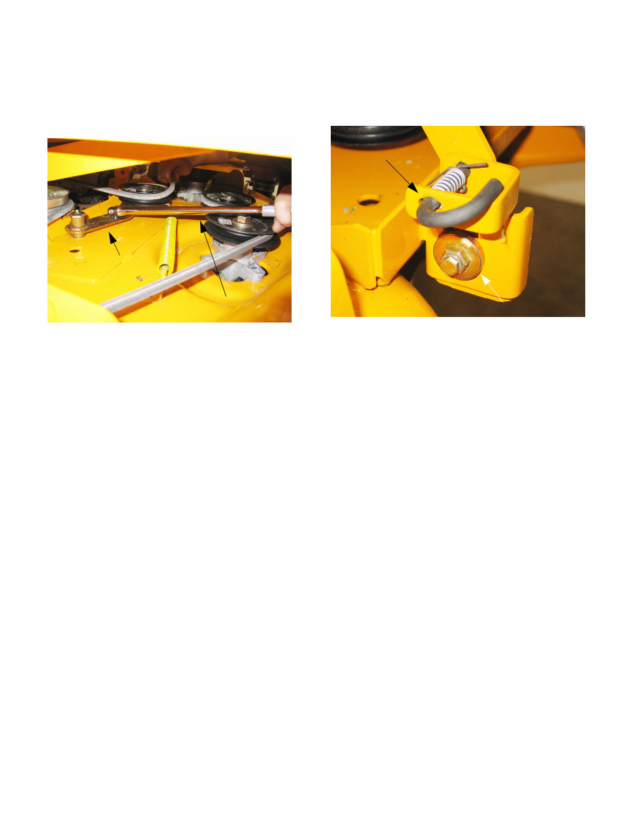
2 2. PTO / DECK BELT REPLACEMENT 2.1. Insert a 1/2” breaker bar into the square hole in the tensioner arm located on top of the deck. See Figure 2.1. 2.2. Pivot the tensioner arm and pulley to slacken the belt. 2.3. Remove the belt from the two stationary idler pulleys and spindle pulleys. NOTE: The spindle covers do not need to be removed. 2.4. Remove the belt from the clutch. 3. DECK REMOVAL 3.1. Release the deck J pins from the rear hanger arms. See Figure 3.1. 3.2. Slide the deck forward until the front stabilizer bar can be lifted away from the front mounting bracket. 3.3. Slide the deck out from underneath the unit. Figure 2.1 1/2” Breaker bar Idler arm Figure 3.1 Deck adjustment gear Deck hanger rod www.mymowerparts.com K&T Saw Shop 606-678-9623 or 606-561-4983
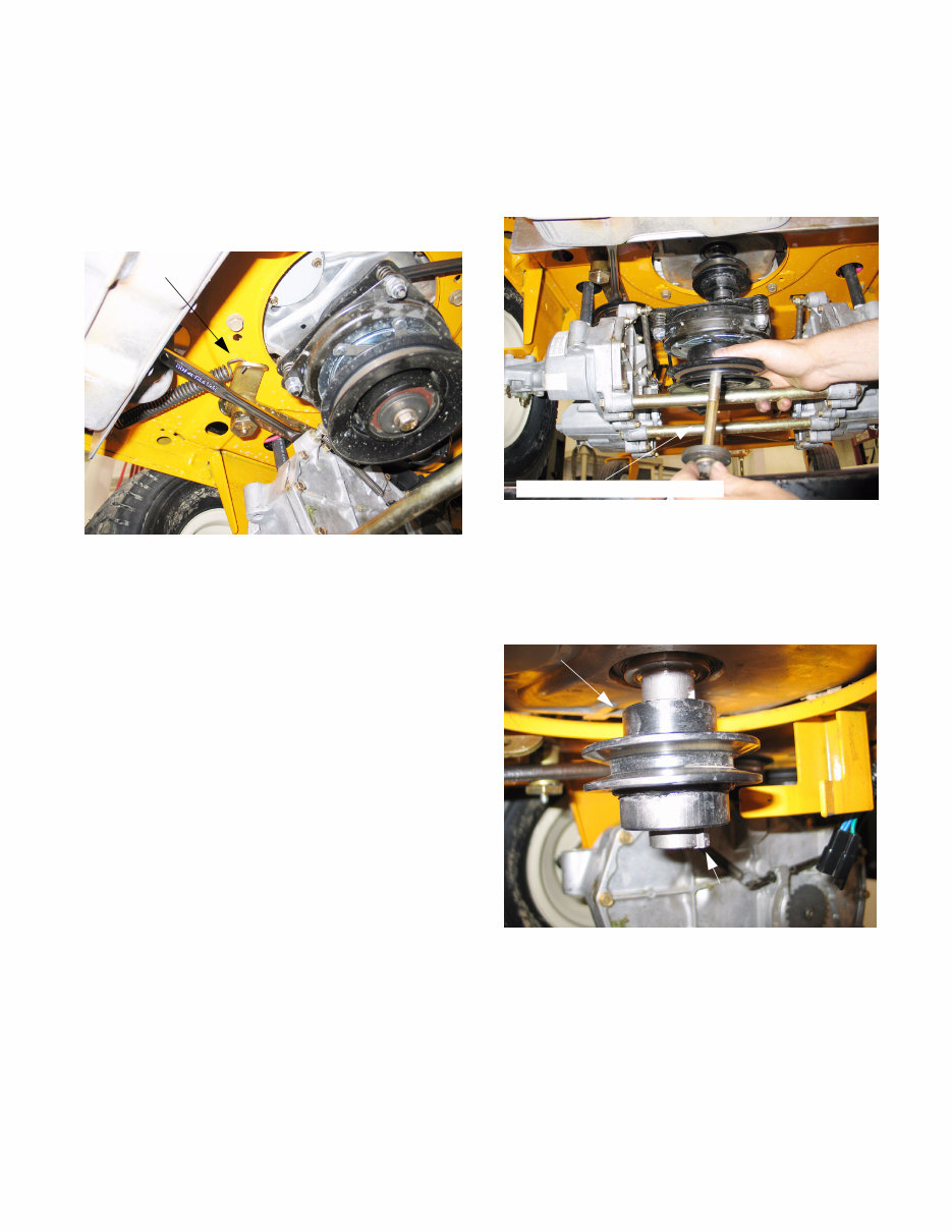
3 4. DRIVE BELT REPLACEMENT 4.1. Insert a 1/2” breaker bar into the square hole on the tensioner arm. 4.2. Pull the breaker bar to the right until it can be braced in position at the pivot point of the ten- sioner arm. See Figure 4.2. 4.3. Remove the belt from the transmission pulleys, tensioner pulley and the crankshaft pulley. Figure 4.2 Idler arm 5. SERVICING ELECTRIC PTO CLUTCH 5.1. Unplug the clutch. 5.2. Using a 9/16” socket and an impact wrench, remove the clutch bolt. See Figure 5.2. 5.3. Lower the clutch off of the crankshaft. 5.4. Remove the crankshaft key. 5.5. Remove the crankshaft pulley. See Figure 5.5. Figure 5.2 7/16-20 x 4.0 Hex cap screw Figure 5.5 Key Crankshaft pulley www.mymowerparts.com K&T Saw Shop 606-678-9623 or 606-561-4983
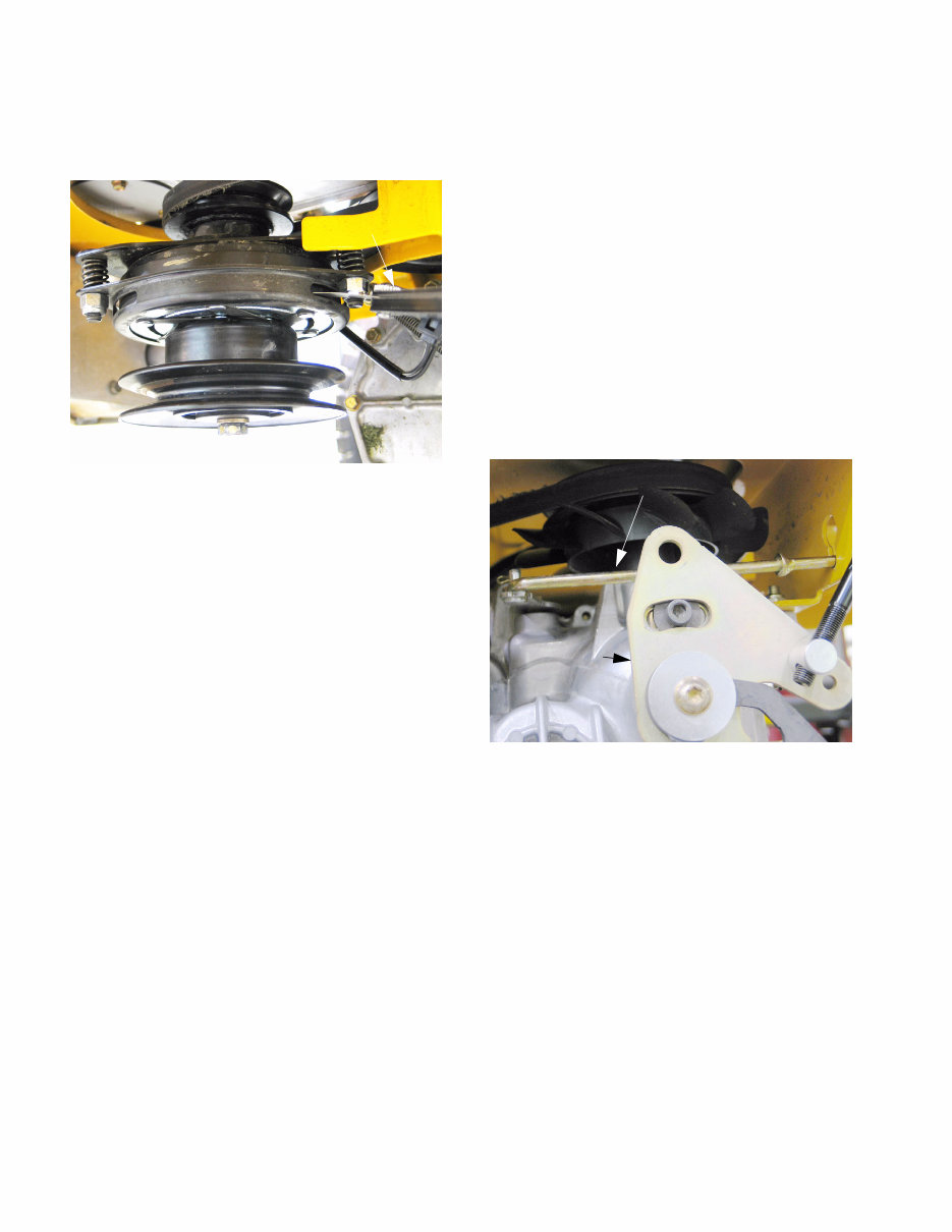
4 5.6. Use a 9/16” socket to adjust the air gap on the clutch to between.010” and.015”. See Figure 5.6. NOTE: Clutch adjustment can be done with the clutch in the unit. If a new clutch is being put in the adjustment can be done on the bench. 6. TRANSMISSION REPLACEMENT 6.1. Insert a 1/2” breaker bar into the square hole on the tensioner arm. 6.2. Pull the breaker bar to the right until it can be braced in position at the pivot point of the ten- sioner arm. 6.3. Remove the belt from the transmission pulleys, tensioner pulley and the crankshaft pulley. 6.4. Remove the four lug nuts securing the rear wheel to the axle hub. NOTE: Insure the lap bar control rods and brake rods are not rubbing against the frame. 6.5. Remove the cotter pin securing the bypass rod to the transmission bypass arm. Remove the bypass rod. See Figure 6.5. Figure 5.6 .012 Feeler gage Figure 6.5 Bypass rod Neutral adjustment plate www.mymowerparts.com K&T Saw Shop 606-678-9623 or 606-561-4983
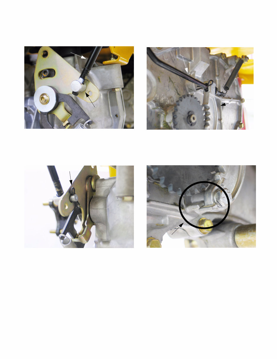
5 6.6. Mark the lap bar control rod threads near the cle- vis pin. See Figure 6.6. 6.7. Remove the hairpin securing the lap bar control rod to the transmission return assembly. See Figure 6.7. Figure 6.6 Lap bar control rod Ferrule Figure 6.7 Hair pin 6.8. Disconnect the brake return spring from the brake arm. See Figure 6.8. 6.9. Remove the bolt securing the brake arm to the transmission using a 7/16” socket. See Figure 6.9. NOTE: A spacer is located between the brake arm and transmission housing. NOTE: During installation, the bottom ridge of the brake arm needs to be below the emboss- ment on the transmission housing. Improper installation will prevent the brake from engaging. 6.10. Remove both bolts securing the tubular trans- mission brace using a 5/8” socket. NOTE: When installing the brace bolts use loc- tite 242. Figure 6.8 Brake arm Brake rod Figure 6.9 Note proper installation www.mymowerparts.com K&T Saw Shop 606-678-9623 or 606-561-4983
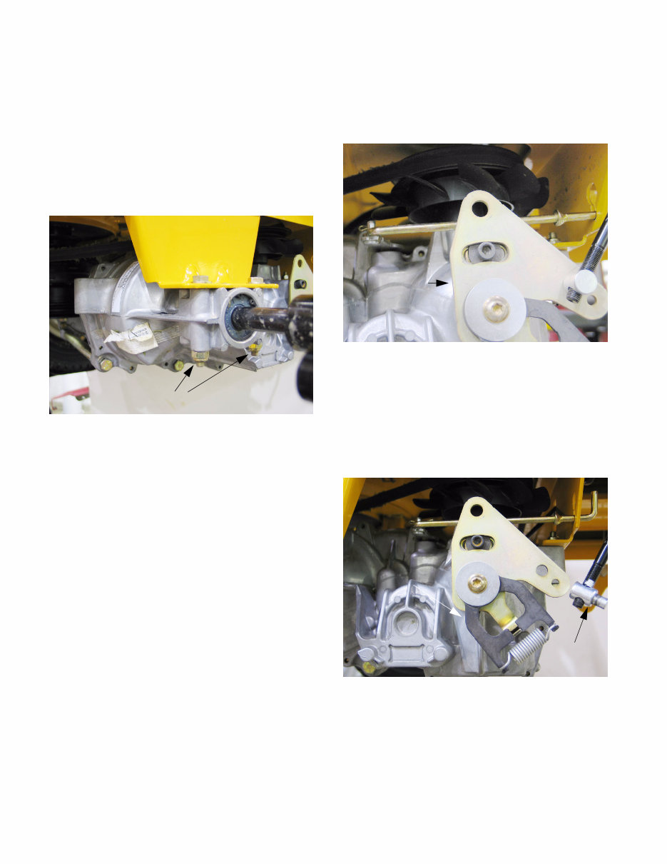
6 6.11. Remove the front transmission mounting bolt using a 1/2” wrench and a 1/2” socket. NOTE: Secure the transmission or use another technician to support the transmission while per- forming the next step. 6.12. Remove both transmission mounting bolts securing the transmission to the mounting bracket using two 1/2” wrenches. See Figure 6.12. 6.13. Rotate the transmission out and down until the fan is clear of the front transmission mounting bracket, and remove it from the frame. 6.14. Installation notes: • Lift transmission into place and start all threaded fasteners before tightening any individual fasten- ers. • The remainder of the installation process con- sists of reversing the removal process. • Tighten the lug nuts to a torque of 350-500 in- lbs. • Tighten the center wheel hub nut to a torque of 100-160 ftlb. 7. STEERING LINKAGE: ADJUSTMENT 7.1. Begin to adjust the steering by confirming that both EZTs are correctly adjusted for neutral con- trol. See Figure 7.1. 7.2. Lift and safely support the rear of the mower. 7.3. Disconnect the ferrule at the EZT end of each lap bar control rod from the neutral return assembly on each of the EZTs. The ferrules are secured to the neutral return assemblies with hairpin clips. See Figure 7.3. NOTE: In the course of normal service, it is very unusual for the neutral return assemblies to require adjustment unless someone has previ- ously tampered with it. It is necessary to check the adjustment because the rest of the proce- Figure 6.12 Transmission Mounting Bolts Figure 7.1 Neutral adjustment plate Figure 7.3 Ferrule www.mymowerparts.com K&T Saw Shop 606-678-9623 or 606-561-4983
Thank you for considering this comprehensive Service & Repair Workshop Manual for the Cub Cadet RZT Zero Turn Rider Mower 2014-2015.
This manual is an invaluable resource for both professional mechanics and DIY enthusiasts, covering every service and repair procedure with easy-to-follow step-by-step instructions and detailed pictures.
By utilizing this manual, you can save a significant amount of money by performing your own repairs. It provides the flexibility to print out specific pages, chapters, or the entire manual, and can also be saved to a tablet or smartphone for easy access.
All models, engines, trim, and transmission types are included in this manual, ensuring comprehensive coverage for a wide range of needs.
The high-quality Service Repair Workshop Manual encompasses all repair procedures from A to Z, guaranteeing that every repair and service procedure is thoroughly addressed.
Compatible with all PC and MAC computers, tablets, and mobile phones, this manual requires only Adobe Reader, which is typically pre-installed on most computers or can be downloaded for free.
Upon payment via Visa, MasterCard, or PayPal, the manual will be instantly emailed to the address provided during checkout, ensuring prompt access to the valuable information it contains.
Customer satisfaction is guaranteed, making this manual a reliable and essential tool for maintaining and repairing the Cub Cadet RZT Zero Turn Rider Mower.
Recently Viewed
5,521,897Happy Clients
2,594,462eManuals
1,120,453Trusted Sellers
15Years in Business
Price:
Actual Price:
Cub Cadet RZT Zero Turn Rider Mower Service & Repair Manual