

MECHANICAL
TRANSMISSION
REPAIR MANUAL
WHEELHORSE
L lawn & garden tctors
Price $3.50
www-MyWheelHorse-com

FOREWORD
This service and repair manual has been compiled to provide
authorized Wheel Horse service personnel with the proper procedures
and techniques for servicing Wheel Horse mechanical transmissions.
The following index lists all areas covered. It is advisable to read
all of the introductory sections first to gain a proper understanding of
the Wheel Horse mechanical transmission used in each model.
The transmission is a sophisticated piece of machinery. Maintain
strict cleanliness control during all stages of service and repair. Even
a small amount of dirt or other contamination can severely damage
the components.
Product information and specifications are shown herein as of the
time of printing. Wheel Horse Products. Inc. reserves the right to
change product specifications. designs and standard equipment without
notice and without incurring obligation.
www-MyWheelHorse-com

CONTENTS
Page
TRANSMISSION USAGE ART ...... .
SECTION I
5003 • 5010 TRANSMISSIONS 5-14
Removal . . .. . . . . . . . . . .. . . . . . . . . . . . 5
Installation . . . . ... .. . . . . . .. . . . . . . . . 5
Disassembly . . . . . .. . . . . . . . . . . . . . . . . 6-8
Cleaning, Inspection, Bearing and
Oil Seal Replacement . . . . . . . . . . . . . . 8
Assembly .. . . . . . . ... . . . . . . . . . . . . . . 8-9
DIFFERENTIAL OVERHAUL . . . . . . . . . . .. . . 10-11
Disassembly . . . . . . . . . • . . . . . . . . . . . . .
Cleaning, Inspection, Parts Replacement
Assembly . . .. . . . . . . . . ... . . . . . .. . . .
53 AND 5010 SERVICE NOTES . .. . . . . . .
EXPLODED VIEW . . .. . ... . ...... . .. ... .
10
10
11
12
13
PARTS LIST . . . . . . .. . . . . . . . . . .. .. .. .. . 14
SECTION I I
5053 • 5058 3·SPEED UNIDRIVE 1 5-26
Description . . . . . . . . . . .. . .. . . . . . .. . .
15
Removal . . . ... . . . . . . . . . . ... . . . . . . . 15
Replacement . . . . . . . . . . . . . . . . . . . . . . . 16-17
Disassembly . .. . . . . . . . . . . ... . . .. .. . 16-18
Cleaning, Inspection, Bearing and
Oil Seal Rep lacement . . . . . .. . . . . . . . 18
Assembly . . . . . . . . . . .. . . . . . . . . . . . . . 1 9-20
Assembly of 5058 Series with
Bevel Gear Differential . . . . . . . . . . . . 21
DIFFERENTIAL OVERHAUL . . . .. . . . . .. . . . 21-22
Dissassembly (Standard Differentia l) . . .. 21
Assembly (Standard Differentia l) . . .. . . 22
Disassembly (Bevel Gear Differential) . . 22
Assembly (Bevel Gear Differential) . . .. 22
EXPLODED VIEW (5053 TRANSMISSION) . . . 23
PARTS UST (5053 TRANSMISSION) . ..... . 24
EXPLODED VIEW (5058 TRANSMISSION . . . 25
PARTS LIST (5058 TRANSMISSION) ... . . . . 26
SECTION I I I
5060 6-SPEED TRANSMISSION
Description . .. . .. . . . . ... . . . ...... . .
Removal .... .. . . . . ... . . .. . .. . ... . .
Instal lation ... . .. . . . . . . . . . . .. . . ... .
Page
27-36
27
27
27
Disassembly . . . . . . . . . . . . . . . . .. . .. . . 28-29
Cluster Gear . .. . . . . . . . . . . .. . . . . . . . . 29
Cleaning, Inspection, Bearing and
Oil a l Replacement . . . . . . . . . . . . . . 29
Assembly . . . . . . .. . . . . . . . . . . . . . . . . . 30-32
LIMITED SLIP DIFFERENnAL . . . . . . . . . . . . . 32 -34
Disassembly . . . . . . . . . . . . . . . . . . . . . . . 32-33
Assembly . . . . . . . . . . . . . . . . . . . . . . . . . 33-34
EXPLODED VIEW ...... ... . .. .. ... . ... .
PARTS LIST
SECTION IV
4-SPEED UNIDRIVE TRANSMISSION
Description .. . . . . . . . . . . . . . . ..... . . .
Removal . . . . . . . ..... . . . . . . . .. . . . . .
35
36
37-44
37
37
Installation . . . . . . . . . . . . .. . . . . . . . . . . 37
Disassembly . .. . . . . . . . . . . . . . . . . . . . . 37·40
Cleaning, Inspection, Bearing and
Oil Seal Replacement . . . ....... . ... 40
Assembly . . . . . . . .. . . . . . . .. . . ... . . . 40-41
DIFFERENTIAL OVERHAUL . . . .. . . . . . . . . . 42-43
Disassembly . . . . . . . . . . . ... . . . . . . . . . 42
Assembly . . . . . . . . . . . .. . . . . . . . . . . . . 42-43
EXPLODED VIEW . . . . . . . . . . . . . . . . . . . . . . 43
PARTS LIST 44
SECTION V
8-SPEED TRANSMISSION 45-53
Description . . . . . . . . . . . . . . . . . . . . . . . . 45
Removal . . . . . . . . . . . . . . . . . . . . . . . . . . 45
Installation . . . . . . . . . .. . . . . . . . . . . . . . 45
Disassembly . . . .. . . . . . . . . . . . . . . . . . . 45-47
Needle Bearing Replacement . . . . . . . . . 47
Cluster Gear . . . . . . . .. . . ... . . .. . . . . . 47
Cleaning, Inspection, Bearing and
Oil Seal Replacement . . . . . . . . . . . . . . 47
Assembly . . . . . . .. . . . . . .. . . . . . . . . . . 47-50
8-PINION DIFFERENTIAL . .. . . . . . .. . . . .. .
Disassembly . . . .. . .. ... .. . . . .. . . . . .
Assembly . . . .. .. ... . . . . . .. . . . . .. . .
50
50
50
EXPLODED VIEWS . . . . . . . . . . . . . .. . . . . . 51-52
PARTS LIST . . . .. . . . . .. . . . . .......... .
53
-3-
www-MyWheelHorse-com
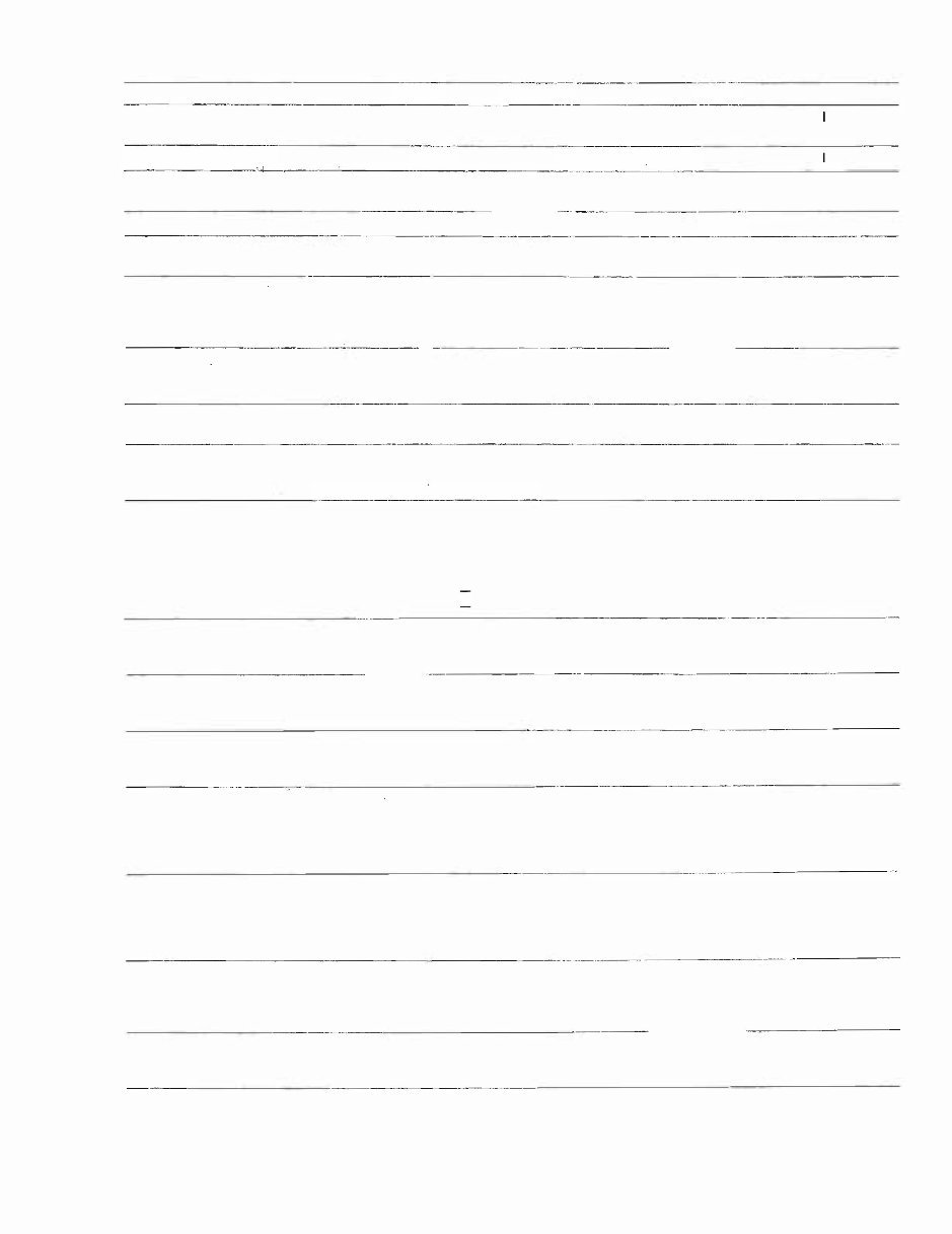
TRANSMISSION USAGE
.. _---_-
YEAR ACTOR MODEl ANSMISSION USED NUAL SECTION
1958
1959
RJ-58 RJ-59
1960 Suburban 1/4001/ & 1/500"
1961 401
551, 701
5003
5010
.
5010
5007
I
1/
... .--�--
1962 502, 552, 702, 32E, 32R
- - -- -
1963 33E, 33R, 603, 633 , 653, 753
1964
953
34E, 34R, 604, 654, 704
854
1045
1054
---_._---._ .. -..
1965
1966
L·l05, l·155
60S, 655, 855, 1055
1054A
_._.
-
l· 106, l-· 156, 606, 656, 1046,
1056, 856
5025 II
5025 II
5045
II
5046
5025
5025
5047
. .... _--_.
II
II
II
II
5048*
II
5049 II
5051 II
._--_--
5053 II
5053 II
--._-----_. -
1967
1968
1969
1970
1971
1972
L.l07, l-157, 607, 657, 857
867, 1067, 1267
1057, 1257
-
lawn Ranger
lawn Ranger
1/500" Special
Commando 6
Commando 8
Raider 9, 10
Raider 12
Workhorse "7001/
Raider 10
Raider 12
Raider 10
Raider 12
Raider 12
Workhorse 1/8001/
Raider 10
Raider 12
Raider 8
Reider 10
Raider 12
Raider 14
Commando "800"
1-2631 Electric
1-1631 Recoil
1-3631
1-4631
1-4831
1-6931 1-6041
1 ·6231 1-6241
1-3745 -1-3741
1-6041
1-6241
.. �----.
1-6051
1-6251
1-6253
1-0100
1-0300
1-0310
1-0330
1-0301
1-0311
1-0320
1-0110
5053 II
5060 III
5058
II
5053
II
5053 II
5053 II
5053 II
5053 II
5060
III
5060 I II
5053
II
5071 I I I
5071 III
5073 V
5073 V
5073 V
5080 IV
5073
V
5073 V
5086 V
5086 V
5073 V
5073 V
5085
IV
- -
1973 8 HP Eight Speed
10 H P Eight Speed
12 HP Eight Speed
14 HP Eight Speed
8 HP Four Speed
1-0370
1-0360
1-0350
1-0340
1-0120
5086
V
5086 V
5073
V
5073
V
5085
IV
- .
- _-- .
-
1974 B-80 4 Speed
C-100 8 Speed
C-120 8 Speed
C-160 8 Speed
1975 B·80 4 Speed
C-100 8 Speed
C-160 8 Speed
Up-dot" 500 50S3 with 71D kit.
1-0140
1-0390
1-0353
1·0380
1-0141
1·0391
1-0381
-4
-
5080, 5084
5091
5091
5091
IV
V
V
V
..•. _ . .
-
5084
5091
5091
IV
V
V
www-MyWheelHorse-com
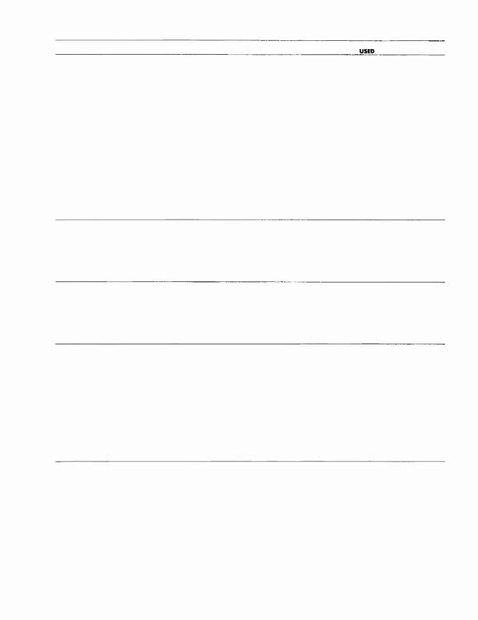
TRANSMISSION USAGE
YEAR TRA ML VIN NUMBER
ANSMISSION MANUAL
US N
1 976 6-< 8-Speed 6 1 -07K80 1 ǽ1 V
6-80 B-Speed 6 1 -08K80 1 , ǽ1 V
6 1 -08K802 &
6 1 -08K804
6-80 B-Speed 61-08K803 1 03Z7 V
6-1 B-Speed 61-10K80I, ǽ1 V
6 1 -IOK802 &
61-10KP4
8-1 8-Speed 61 -IOK803 1 03Z7 V
C-I20 B-Speed 61-12K80I, ǽ1 V
61 -1 2KP2 &
61-1 2KP4
C-I20 B-Speed 61-1 2K803 103Z7 V
C-1 a-Speed 61-16KBOI, ǽ1 V
6 1 - 1 6KB02 &
61-16K804
C-1 8-Speed 61-1 6K803 1 03Z7 V
1977 8-< 8-Speed 7 1 -07K801 1 03Z7 V
8-80 8-Speed 7 1 -08K801 1 03Z7 V
8-1 a-Speed 7 1 - 1 0K80 1 1 03Z7 V
C-I20 8-Speed 7 1 - 1 2K80 1 1 03Z7 V
C- 1 a-Speed 7 1 - 1 6K80 1 & 1 03Z7 V
71-16K802
1 978 C-81 B-Speed 81-08K801 1 03916 V
C-10 1 8-Speed 8 1 -IOK801 1 03916 V
C-121 8-Speed BI-1 2K801 1 03916 V
C-1 41 8-Speed BI- 1 4K801 1039 16 V
C-16 1 8-Speed 81-1 6K80 1 1 039 1 6 V
C-1 61 Twin 8-Speed BI-168801 103916 V
1 979 C-81 B-Speed 9 1 -(K80 1 & 103916 V
9 1 -(KP2
C-101 B-Speed 91-IOKP1 & 1 039 1 6 V
9 1 - 1 0KP2
C-III B-Speed 9 1 - 1 1 6801 1 039 1 6 V
C-12 1 8-Speed 9 1 - 1 2K801 & 103916 V
91-12KP2
C- 1 41 8-Speed 9 1 - 1 4K80 1 & 1 039 1 6 V
9 1 - 1 4KP2
C-1 61 8-Speed 91-16K80 1 1 039 1 6 V
C-161 Twin 8-Speed 91-166801 & 103916 V
91-166P2
- 4A -
www-MyWheelHorse-com

TRANSMISSION USAGE
YEAR TRA MOÞL VIN NUMBER
TRANSMISSI MANUAL
USED SEI
1 980 C-85 8-Speed 01 -08KP1 & 103916 V
0 1 -08K802
C-1 05 8-Speed 01-10KP1 1 039 1 6 V
1 1 Special 01- 1 1 B803 5086 V
C-1 25 8-Speed 0l-1 2KP1 1 0391 6 V
C-1 45 8-Speed 01- 1 4KP1 1 039 16 V
C-l65 8-Speed 01- 1 6KP1 1 039 16 V
C-1 75 Twin 8-Speed 01- 1 7K802 1 039 16 V
E-1 41 8-Speed 01 -1 4E801 103918 V
1981 C-85 8-Speed 0 1 -08K802 1 039 1 6 V
C- 1 05 8-Speed 0 1 - 1 0K802 1 0391 6 V
C-1 25 8-Speed 01- 1 2K802 1 03916 V
C- 1 45 8-Speed 0 1 - 1 4K802 103916 V
C-1 65 8-Speed 0 1 - 1 6K802 103916 V
C-1 75 Twin 8-Speed 0 1 - 1 7K802 1 03916 V
E-1 41 8-Speed 01- 1 4E801 1 039 18 V
GT-220 8-Speed 01- 1 1 B804 Ꮮ V
1 982 C-85 8-Speed 0 1 -08K803 1 039 16 V
C-1 05 8-Speed 0 1 -lOK803 1 039 16 V
C-1 25 8-Speed 0 1 - 1 2K803 1 039 16 V
C-1 75 Twin 8-Speed 01- 1 7KP3 103916 V
E-1 4 1 8-Speed 01- 1 4E801 1 0391 6 V
GT-1 1 42 8-Speed Al- 1 1 420l Ꮮ V
GT- 1 @2 8-Speed Al-1 @201 2V V
SB-421 8-Speed 01- 1 1 BH01 5V V
SK-4V 8-Speed 01 -1 6KH01 Ꮮ V
- 48-
www-MyWheelHorse-com

Section I
5003 • 5010 TRANSMISS IONS
DESCRIPTION
The 5003 and 5010 transmissions are readily iden-
tifted by their removable steel side covers wh ich are
bolted to a one piece cast iron case. The transmissions
are of the sliding gear type and provide three speeds
forward and one speed in reverse.
All shafts operate on needle or ball bearings sup-
ported by the steel side covers.
The differential is of the spur pin ion type. On all
original equ ipment transmissions, the ring gear is an
integral part of the d ifferential case. The s,rvice reo
placement, however, consists of a case and gear as·
sembly in which the gear is bolted to the d ifferential
case.
RATIOS
lst gear . . . . . . . . . . . . . .. 6 6.8 to
2nd gear . . . . . . . . . .. . . . 42.4 to
3rd gear . . . . . . . . . . . . . . . 24.6 to
Rever . . . . . . . . . . . . . . . 5 1 . 5 to
REMOVAL AND REPLACEMENT
Removal:
Remove any mid-mounted or trailing attachment
which might interfere with transmiss ion removal.
Provide. some support under the tractor frame ahead
of the transmission.
Remove the seat, fender and tool box assembly if
so equipped, belt guard, belt , and clutch rod. Discon-
nect the lift cable and remove the hitch.
Installation:
Instal l c lutch and idler arm asmbly, brake rod,
and input pulley. Instal l whee ls and hubs and move
assembly into place on the tractor. Install three bolts
through holes in each transmiss ion side cover and
corresponding holes in frame side rails. Tighten nuts
securely.
-5 -
Remove three bolts at each transmiss ion side cover
and frame side rail. Move transmiss ion assembly
away from the tractor. Remove the wheels and hubs,
clutch and idler arm assembly, and transmiss ion in-
put pul ley.
Drain lubr icant and clean case as necessary be-
fore disassembl ing.
Install drive belt and belt guard. Connect clutch
rod. lay lift cable in p lace along top of transmission,
instal l hitch and connect lift cable.
Install fender and tool box assembly if so
equipped, and instal l seat. Remove support from be-
neath tractor frame.
www-MyWheelHorse-com
500]·5010 ].SPEED TRANSMISSION
Disassembly:
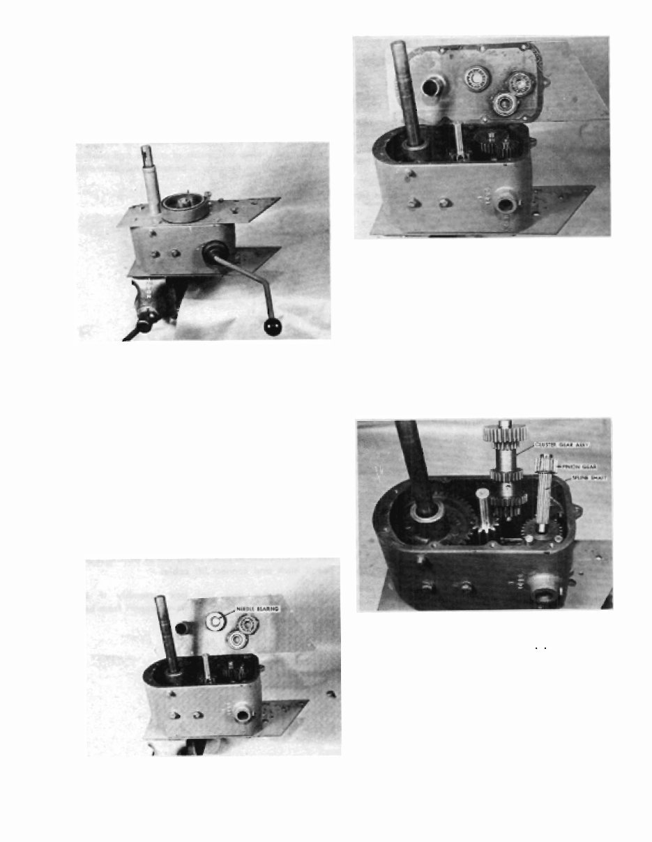
The transmission should be mounted in a vise or
suitable fixture as shown in Figure 1, with the left
cover up and the gear shift lever and top of the case
toward the mechanic working on the unit.
FIGURE 1
The following steps are for complete disassembly
with the transmission in the vise, as shown in Fig-
ure 1.
1. Lift the rubber shift lever boot and loo�en the
shift lever set screw and lock nut, and remove
the shift lever.
2. Remove the two bolts that hold the brake band
to the side cover bracket and remove the brake
band.
3. Remove the snap ring (some models may have
a set screw) from the brake shaft and remove
the drum using a suit able puller as requi red.
Remove the Woodruff key from the brake shaft.
FIGURE 2
-6 -
GURE 3
4. Clean and remove all burrs from both axle
shafts and brake shaft and remove both axle
seals.
5. Remove the nine left cover retaining bolts and
lift off the cover. NOTE: Figures 2 and 3 show
the two types of covers used on these transmis-
sions, one with a ball bearing and one with a
needle bearing at the brake shaft location. Re-
placement information for each type is given in
Service Notes 1 and 2, Page 12.
FIGURE 4
6. Remove the spline shaft and pinion gear. See
Figure 4. NOTE: The shaft and matching gears in
some transmissi ons have 10 splines while later
models have 11 splines. For details and ordering
information, refer to Service Note 3, Page 12.
7. Remove the bolts from t he right cover and break
the case loose from the cover gasket. This will
allow the case t o shift sufficiently to let the clus-
ter gear assembly to be worked loo and re-
www-MyWheelHorse-com
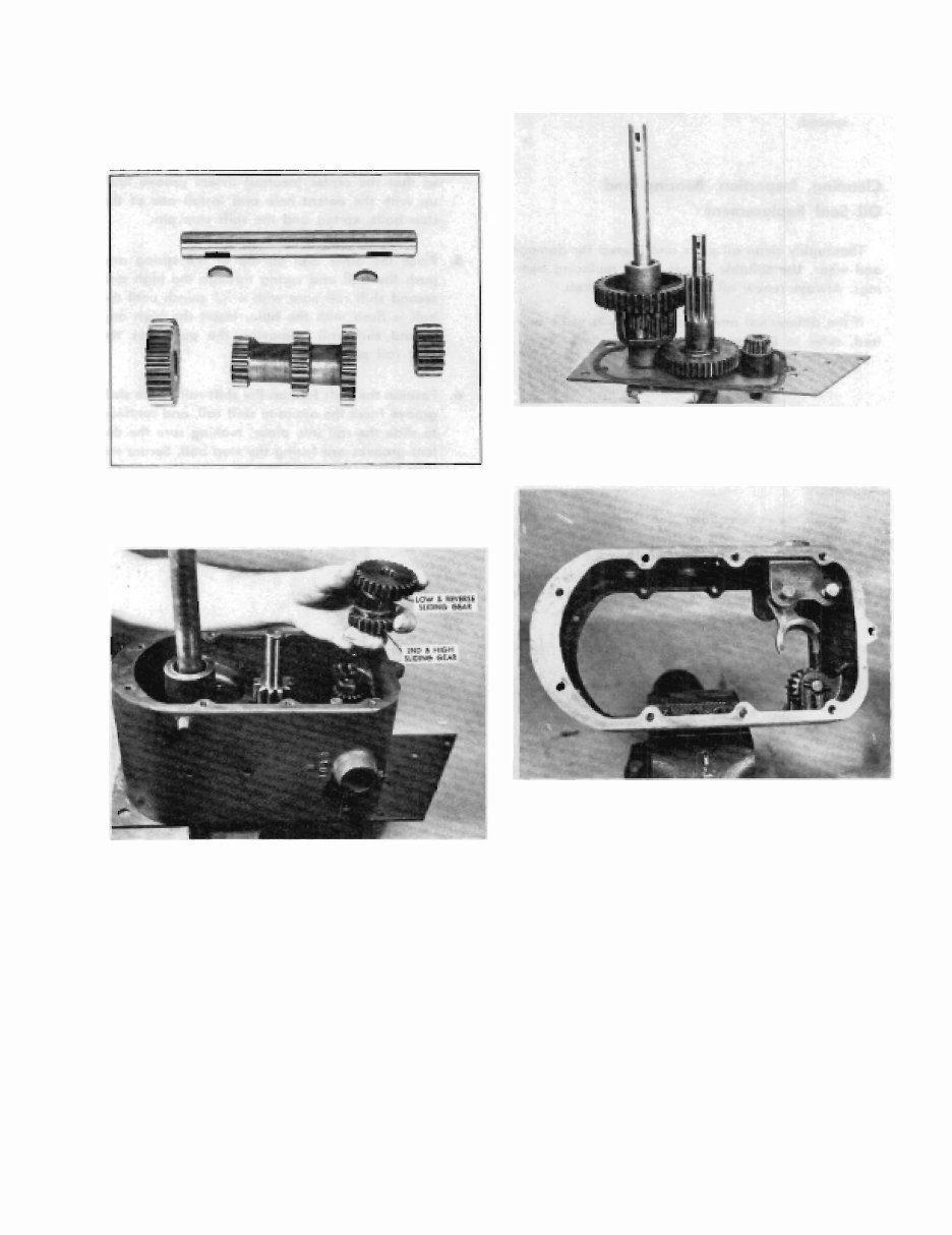
moved, as shown in Figure 4. The cluster gear
may be disassembled as shown in F igure 5. Dis-
assemble and assemble carefu l ly to avoid dam-
age to the Woodruff keys and bushings. The
cluster gear bushings may be removed an d in-
stalled using suitable arbors.
GURE 5
GURE 6
8. Remove the low and reverse, and the hIgh and
second sliding gears. If either gear is to be re-
placed, refer to Service Note 3. Page 9.
9. lift the brake shaft gear s lightly, and rotate the
transmission case to the right and upward. over
the top of the input gear. Position the case so
that the differential ring gear is centered be·
tween the two seat spring bosses. The case may
now be removed by working it up over the dif-
ferential ring gear.
-1-
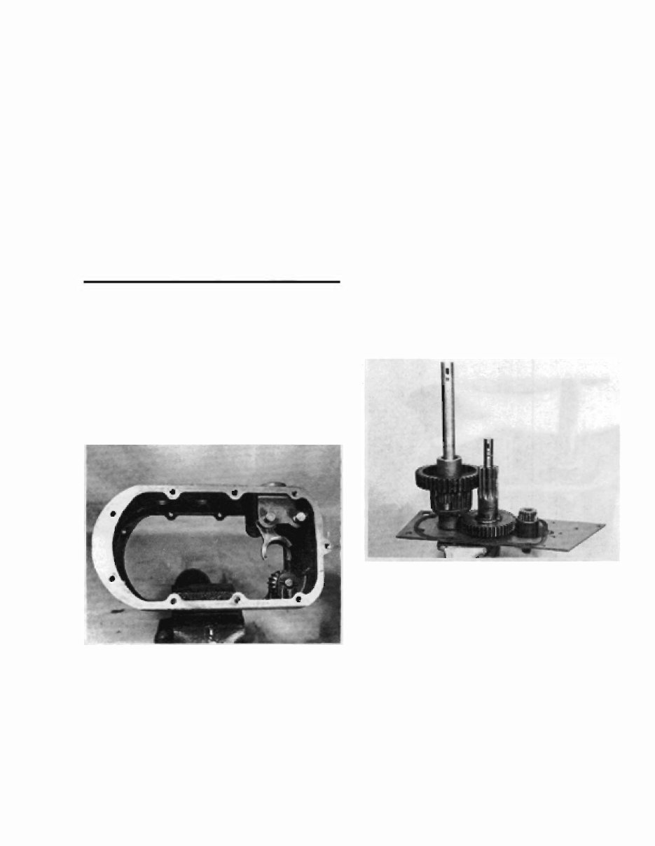
1 0. Remove the differential and axle assembly, the
brake shaft gear and the input gear and shaft.
See Figure 7. Remove the input shaft seal.
FIGURE 1
FIGURE 8
11. To remove the reverse idler gear, dr i ve out the
roll pin from the idler gear pin and remove the
pin a nd gear. See Figure 8. (Early models used
a roll pin at each end of the idler gear p in.)
12. Before removing the shift forks and shift rails.
mating parts should be marked or scribed so
they may be reassembled properly. The shif t
fork retaining roll pins may be removed by dr iv-
ing them out with a X" punch inserted thro ugh
the shift lever tower. Remove the shift rails mak·
ing sure to catch the two balls, spring and stop
pin as they are released. NOTE: Althoug h the
shift forks are identical, the shift rai ls differ.
The low and reverse shift rail (located nearest
www-MyWheelHorse-com
the end of the case) has three equally spaced
detent grooves. The high and second shift ra il
has two of the three det ent grooves closely
spaced.
Cleaning, Inspection, Bearing and
Oil Seal Replacement
Thoroughly clean all parts and inspect for damage
and wear. Use suitable arbors when replacing bear-
ings. Always renew all oi l seals and gaskets.
If the differential and ax le assembly is to be serv-
iced, refer to Differential Overhaul Section.
5003 ·5010 3·SPEED TRANSMISS ION
Assembly:
1. Install the reverse idler gear in position so that
the chamfered end of the gear faces the left
side of the case. This will position the gear with
the straight edge toward the right side of the
case, as shown i n Figure 9. Install the reverse
idler pin and secure with a K," roll pin.
- -
.
-
I
FIGURE 9
2. Position the low and reverse shift fork (the one
nearest the e nd of the case) between the shift
rail supports so that the shift lever groove points
toward the opposite shift rail.
3. Insert the low and reverse shift rail (the one
with the equally spaced detent grooves) and
-8-
slide into position, making sure the detent
grooves are toward the opposite shift rail. -
cure the shift fork to the s hift rail with a "
x 1" roll pin.
4_ Position the low and reverse shift rail assembly
so that the center (neutral) detent groove lines
up with the detent hole and install one of the
stop balls, spring and the shift stop pin.
5. Place th e other bal l on top of the spring and
push the ball and spring through the high and
second shift rail bore with a K6" punch until the
�all is flush with the bore. Insert the high and
second shift rail, removing the punch as the
shift rail passes the ball.
6. Position the shift fork on the shift rail so the shift
Qroove faces the opposite shift rail, and continue
to slide the rail into place, making sure the de-
tent grooves are facing the stop ball. Secure the
shift fork to the shift rail with a " x 1" roll pin.
FIGURE 1 0
7. Place the right side cover in a vise. Install the
input gear and shaft assembly. See Figure 10.
8. Install the side cover gasket using gas ket sealer
to hold in position.
9. Install the brake shaft gear.
1 0. Install the different ial and axle assembly. Ser
Figure 10 showing the input gear, brake shafl
gear and differential assembly in position.
www-MyWheelHorse-com
You're Reading a Preview
What's Included?
 Lifetime Access
Fast Download Speeds
Online & Offline Access
Access PDF Contents & Bookmarks
Full Search Facility
Print one or all pages of your manual
$31.99
Wheel horse tractors unidrive transmission repair service ma
Viewed 53 Times Today

What's Included?
Lifetime Access
Fast Download Speeds
Online & Offline Access
Access PDF Contents & Bookmarks
Full Search Facility
Print one or all pages of your manual
$31.99

Secure transaction
What's Included?
Lifetime Access
Fast Download Speeds
Online & Offline Access
Access PDF Contents & Bookmarks
Full Search Facility
Print one or all pages of your manual
Description
Covering the 1958-1982 Unidrive transmission, this manual is designed for easy filing and viewing. It is always in new condition, making it easier to find pages and print only what you need. The .S files allow for easy zooming in and out for better viewing.
- File Format: .S
- Compatible: All Versions of Windows, Mac, and Linux
- Printable: Yes
- Speed: Instant High Speed
- Requirements: Adobe Reader
This manual is easy to understand and navigate, making it useful for both professional mechanics and DIY enthusiasts.


