

Wheel Horse tractor hydrostatic transmission service manual
What's Included?
Fast Download Speeds
Online & Offline Access
Access PDF Contents & Bookmarks
Full Search Facility
Print one or all pages of your manual
OF===~---l
o
AUTOMATIC
TRANSMISSION
REPAIR MANUAL
SUNDSTRAND HYDROSTATIC SYSTEMS
Hydrogear & Piston - Piston, 1965-1982
WIIEEL HORSE
1-.---1 lawn & garden tractors
Part No. 492-4206
(Formerly A-1391, 803402)
.....
z
w
~
W
..J
a..
a..
:::l
en
.....
z
w
~
W
..J
a..
a..
:::l
en
.....
z
w
~
W
..J
a..
a..
:::l
en
SUPPLEMENTAL INFORMATION
INTRODUCTION
The following information will assist you with troubleshooting, assembly,
and repair information, in light of changes made and experience gained since this
manual was first published in 1974. It also contains special service information for
1978-82 model year Sundstrand units.
SERVICE AND REPAIR PARTS
• Hydrogear Conversions - Many hydrogear units (1966 to mid-1973)
have been converted to the serviceable piston-piston transmission.
Refer to the photos in this manual to identify the transmission in a
particular tractor.
• Complete Transmissions - Complete replacement transmission
assemblies are no longer available. Independent outside rebuilding
service many be available. Refer to the latest issue of Service
Bulletin 437 for information.
•
Repair Parts - Use this manual to determine replacement part
numbers for 1965 to mid-1973 hydrogear units (Pages 54-56) and
mid-1973 to 1977 piston-piston units (Pages 60-62). Be sure to
check parts price list to determine if all parts needed are still
available before ordering parts.
Piston-piston part numbers for 1978-82 model year tractors are
contained in the particular tractor parts manual.
• D-Series Adjustments - Transmission control linkage adjustments
described in this manual for 1975 models are appropriate for 1976-
77 models. 1978-82 linkage adjustments are covered in the 1978-79
B,C,D- Series Service Manual, PIN 810063R1.
• D-Series Driven Coupling Preload and Pump Alignment - Refer to
Service Bulletins 217 and 305 for special service information .
CONSTRUCTION CHANGES, 1978 AND LATER
• Sundstrand units on 1978 and later tractors differ from earlier units in
that the motor shaft extends through the cover plate, for the
mounting of a parking brake drum. Motor repair operations
described in this manual still apply, except that the motor cover plate
oil seal should be replaced during the repair process.
Supplement 1
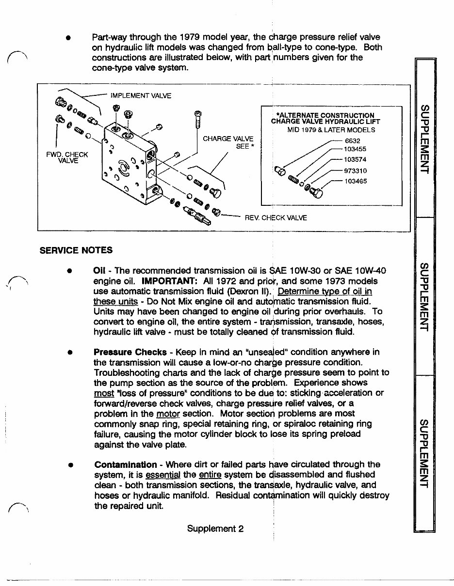
• Part-way through the 1979 model year, the charge pressure relief valve
on hydraulic lift models was changed from ~all-type to cone-type. Both
constructions are illustrated below, with part numbers given for the
cone-type valve system.
FWD. CHECK
VALVE
*ALTERNATE CONSTRUCTION
CHARGE VALVE HYDRAULIC LIFT
MID 1979 & LATER MODELS
4
6632
~
103455
~~103574
'ce /~973310
~o /~103465
:'0 0... ~ <lqzj
o ~, ~~--------------------~
~~- REV.CHECKVALVE
SERVICE NOTES
•
•
•
Oil - The recommended transmission oil is SAE 10W-30 or SAE 10W-40
engine oil. IMPORTANT: All 1972 and pritt, and some 1973 models
use automatic transmission fluid (Dexron II).' Determine type of oil in
these units - Do Not Mix engine oil and autqmatic transmission fluid.
Units may have been changed to engine oil during prior overhauls. To
convert to engine oil, the entire system - transmission, transaxle, hoses,
hydraulic lift valve - must be totally deaned bf transmission fluid.
Pressure Checks - Keep in mind an uunsealedll condition anywhere in
the transmission will cause a low-or-no charge pressure condition.
Troubleshooting charts and the lack of charge pressure seem to point to
the pump section as the source of the problem. Experience shows
most ·,oss of pressure" conditions to be du~ to: sticking-acceleration or
forward/reverse check valves, charge press~re relief valves, or a
problem in the motor section. Motor section problems are most
commonly snap ring, special retaining ring, br spiraloc retaining ring
failure, causing the motor cylinder block to Ipse its spring preload
against the valve plate.
Contamination - Where dirt or failed parts have circulated through the
system, it is essential the entire system be Qisassembled and flushed
dean - both transmission sections, the transaxle, hydraulic valve, and
hoses or hydraulic manifold. Residual contamination will quickly destroy
the repaired unit.
Supplement 2
(J)
C
"0
"0
,...
m
;:
m
~
(J)
C
"0
"0
Iii
;:
m
~
(J)
C
"0
"0
,...
m
;:
m
~
•
Valve Plates - Note the difference betWeen the pump and motor valve
plates (Fig. 44). Ensure the correct valve plate is ordered when
replacing, as the motor plate will fit in place of the pump plate, but will
not function properly. Scratches in the brass surface of the plate that
can be felt with a fingernail indicate an unserviceable valve plate. The
.....
cylinder block may also be unserviceable in this case.
Z
W
~
•
Charge and Implement Valves - Note the location of these valves,
W
-I
depending on whether the tractor has manual or hydraulic lift (Fig. 61).
a..
a..
Using the appropriate valve parts in the correct hole permits setting up
:::> any piston-piston unit for either type of lift system.
C/)
•
Ch~rge Pump - Refer to the installation of the charge pump (Fig. 49).
With the pump end cap positioned as shown, note that the dowel pin is
down (nearest the sealing surface of the pump end cap). The charge
-
pump can be put on upside-down, and will fail to function.
Also note that the charge pump needle bearing, Fig. 54, must protrude
above the housing surface, to hold the valve plate in place. Use care to
prevent accidentally pressing the dowel pin into the housing. Be sure
.....
the valve plate notch is over the dowelJllil on assembly, or the valve
Z
W
plate will be ruined.
!\.
~
I
W
•
Control Shaft/Stub Shaft - On 1978 and later transmissions, the longer
--
-I
a..
control shaft is used on both sides of the pump housing (Fig. 57).
a..
Using a later transmission on an earlier tractor may require cutting a
:::>
C/)
clearance hole in the tractor's sheet metal for the longer shaft.
•
Acceleration Valves - Original equipment valves are different (Fig. 68)
and must not be exchanged during repair. However, the forward valve
is used as the service replacement part for both locations.
If an acceleration valve seems to be malfunctioning, ensure the metering
plug hole is open (Fig. 70). If clogged, it will prevent the valve from
closing. The hole is extremely smalj, and it may take a magnifying glass
.....
to see it.
Z
W
•
Motor Section - Note that the webbed section of motor housing must
~
W
be "up" (Fig. 74), or motor will run opposite the intended direction.
...J
a..
a.. Special Assembly Note
:::>
C/)
Ensure you use new retaining parts in the motor section (Items
23,70,73,74, Pages 61-62), to ensure the integrity of the cylinder block
~I
attachment to the motor shaft. On assembly, make absolute~ ~ur~ the
cylinder block is locked securely on the motor shaft. Be sure the notch
in the valve plate is over the dowel pin in the motor end cap.
Supplement 3
'~--~---------~- -- ~
-----
FOREWORD
This service and repair manual has been compiled to provide
authorized Wheel Horse service personnel with the proper procedures
and techniques for servicing Wheel Horse automatic transmissions.
The following index lists all areas covered. It is advisable to read
all of the introductory sections first to gain a proper understanding of
the Wheel Horse automatic transmission.
The automatic transmission is a sophisticated piece of machinery.
Maintain strict cleanliness control during all stages of service and
repair. Even a small amount of dirt or other contamination can severely
damage the system.
Although this manual deals primarily with the Sundstrand piston-
piston type hydrostatic transmission, service and repair procedures for
the older hydrogear type transmission have beeo included in a separate
section.
-1-

SUNDSTRAND HYDROSTATIC TRANSMISSION MANUAL
Table of Contents – Page 1 of 3
SUPPLEMENTAL INFORMATION
INTRODUCTION
SERVICE AND REPAIR PARTS
CONSTRUCTION CHANGES, 1978 AND LATER
SERVICE NOTES
SPECIAL ASSEMBLY NOTE
FOREWORD
PRINCIPLES OF OPERATION
RELIEF VALVES
FORWARD TRAVEL
REVERSE TRAVEL
ACCELERATION VALVES
PUSH VALVE
DIAGNOSIS
TROUBLE-SHOOTING CHARTS
ENGINE CHART
SPEED CONTROL LINKAGE AND ADJUSTMENTS--STANDARD SYSTEM
NEUTRAL ADJUSTMENT
FRICTION ADJUSTMENT
SPEED CONTROL LINKAGE AND ADJUSTMENTS—SEPARATED SYSTEM
1973 18 HP AUTOMATIC--NEUTRAL ADJUSTMENT
FRICTION ADJUSTMENT
PARKING BRAKE ADJUSTMENT
1974 "D" SERIES TRACTORS--NEUTRAL ADJUSTMENT (FIG. 8)
LEVER POSITION ADJUSTMENT
FRICTION ADJUSTMENT -- SPEED CONTROL LEVER
FRICTION ADJUSTMENT--PARKING BRAKE
PARKING BRAKE ADJUSTMENT
1975 "D" SERIES TRACTORS -- NEUTRAL ADJUSTMENT
LEVER FRICTION ADJUSTMENT
PARKING BRAKE ADJUSTMENT
PRESSURE TESTING
CHARGE PRESSURE TEST
IMPLEMENT PRESSURE TEST
REPAIR PROCEDURES -
SEPARATION OF PUMP AND MOTOR
SEAL RING INSTALLATION & ASSEMBLY OF PUMP TO MOTOR

SUNDSTRAND HYDROSTATIC TRANSMISSION MANUAL
Table of Contents – Page 2 of 3
REMOVAL OF HYDROSTATIC UNIT FROM A STANDARD SYSTEM
INSTALLATION OF HYDROSTATIC UNIT IN A STANDARD SYSTEM
REMOVAL OF HYDROSTATIC UNIT FROM A SEPARATED SYSTEM
MOTOR REMOVAL
PUMP REMOVAL
INSTALLATION OF HYDROSTATIC UNIT IN A SEPARATED
PUMP INSTALLATION
MANIFOLD INSTALLATION
MOTOR INSTALLATION
INSPECTION OF PARTS
PUMP AND MOTOR SHAFTS
CYLINDER BLOCK ASSEMBLIES--GENERAL
CYLINDER BLOCK FACE
PISTONS AND SLIPPERS
SLIPPER RETAINERS
VALVE PLATES
THRUST PLATES
CHARGE PUMP ASSEMBLY
BEARINGS (FOR REPLACEMENT SEE DISASSEMBLY AND ASSEMBLY SECTION)
DISASSEMBLY & ASSEMBLY OF HYDROSTATIC PUMP
PUMP HOUSING DISASSEMBLY & ASSEMBLY
DISASSEMBLY
ASSEMBLY OF PUMP HOUSING
ASSEMBLY OF PUMP SECTION
REMOVAL & REPLACEMENT OF ACCELERATION VALVES
DISASSEMBLY
ASSEMBLY
DISASSEMBLY AND ASSEMBLY OF HYDROSTATIC MOTOR
DISASSEMBLY OF MOTOR
ASSEMBLY OF MOTOR
DISASSEMBLY AND ASSEMBLY OF CYLINDER BLOCKS AND PISTON ASSEMBLIES
DISASSEMBLY
ASSEMBLY

SUNDSTRAND HYDROSTATIC TRANSMISSION MANUAL
Table of Contents – Page 3 of 3
HYDROGEAR SECTION
HYDROGEAR TROUBLE-SHOOTING CHART
TROUBLE SHOOTING GUIDE
PRELIMINARY CHECKS
HYDROGEAR TUNE-UP
HYDROGEAR SERVICE NOTE
HYDROGEAR
HYDROGEAR PARTS DRAWING/LIST 1965-73
PUMP SHAFT SEAL REPLACEMENT
THE TRANSAXLE
REMOVAL OF TRANSAXLE COMPLETE WITH HYDROSTATIC UNIT
REMOVAL OF HYDROSTATIC UNIT FROM THE TRANSAXLE
TRANSAXLE DISASSEMBLY
PARKING BRAKE AND OIL FILTER
TRANSAXLE GASKET INSTALLATION
PISTON-PISTON HYDROSTATIC TRANSMISSION 1973-1977
SERVICE BULLETIN RECORD
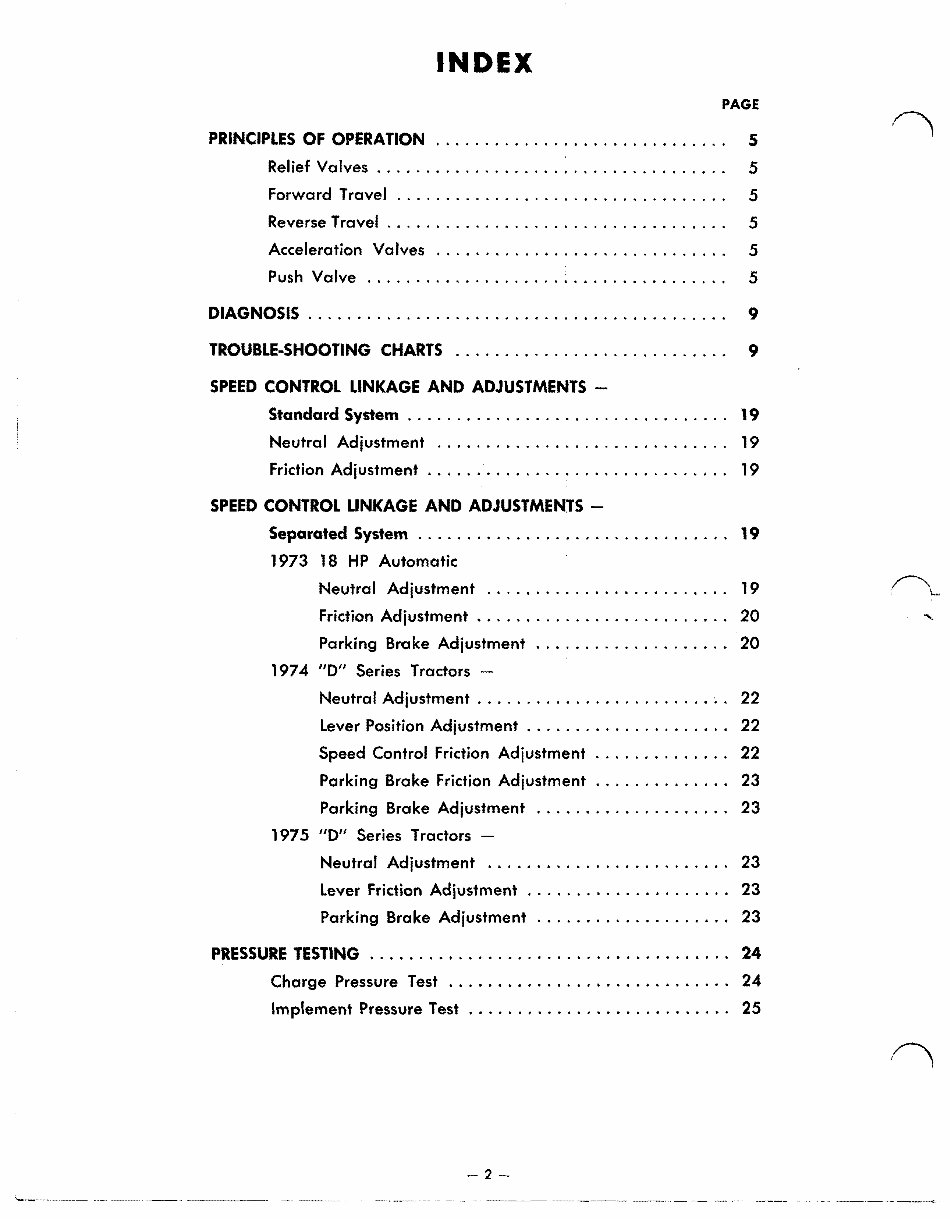
INDEX
PAGE
PRINCIPLES OF OPERATION 5
Relief Valves .................................. " 5
Forward Travel .................................. 5
Reverse Travel . . . . . . . . . . . . . . . . . . . . . . . . . . . . . . . . . .. 5
Acceleration Valves .............................. 5
Push Valve ..................................... 5
DIAGNOSIS . . . . . . . . . . . . . . . . . . . . . . . . . . . . . . . . . . . . . . . . . .. 9
TROUBLE-SHOOTING CHARTS ............................ 9
SPEED CONTROL LINKAGE AND ADJUSTMENTS -
Standard System . . . . . . . . . . . . . . . . . . . . . . . . . . . . . . . .. 19
Neutral Adjustment .............................. 19
Friction Adjustment . . . . . . . . . . . . . . . . . . . . . . . . . . . . . .. 19
SPEED CONTROL LINKAGE AND ADJUSTMENTS -
Separated System ............................... . 19
1973 18 HP Automatic
Neutral Adjustment ........................ . 19 ~ ..
Friction Adjustment ......................... . 20
"
Parking Broke Adjustment ................... . 20
1974- "0
11
Series Tractors -
Neutral Adjustment ........................ ; . 22
Lever Position Adjustment .................... . 22
Speed Control Friction Adjustment ............. . 22
Parking Brake Friction Adjustment ............. . 23
Parking Brake Adjustment ................... . 23
1975 "0" Series Tractors -
Neutral Adjustment ........................ . 23
Lever Friction Adjustment .................... . 23
Parking Brake Adjustment ................... . 23
PRESSURE TESTING .................................... . 24
Charge Pressure Test .................... • ........ 24-
Implement Pressure Test .......................... . 25
2-
.~ .... -~-~--

r,
, \
INDEX
PAGE
REPAIR PROCEDURES ................................... 25
Separation of Pump and Motor ........... '.' ........ 25
Seal Ring Installation ............................. 26
Assembly of Pump to Motor ........................ 26
REMOVAL OF HYDROSTATIC UNIT
FROM A STANDARD SYSTEM . . . . . . . . . . . . . . . . . . . . . . . . . . . .. 26
INSTALLATION OF HYDROSTATIC UNIT
IN A STANDARD SYSTEM . . . . . . . . . . . . . . . . . . . . . . . . . . . . . . .. 26
REMOVAL OF HYDROSTATIC UNIT
FROM A SEPARATED SYSTEM . ............................ 27
Motor Removal .................................. 27
Pump Removal .................................. 27
INSTALLATION OF HYDROSTATIC UNIT
IN A SEPARATED SYSTEM . .............................. 27
Pump Installation ................................ 27
Manifold Installation ............................. 28
Motor Installation ................................ 30
INSPECTION OF PARTS . . . . . . . . . . . . . . . . . .. . . . . . . . . . . . . . .. 32
Pump and Motor Shafts .. . . . . . . . . . . . . . . . . . . . . . . . .. 32
Cylinder Block Assemblies ......................... 32
Cylinder Block Face .............. '. . . . . . . . . . . . . . .. 32
Pistons and Slippers .............................. 32
Slipper Retainers ................................ 33
Valve Plates .................................... 33
Thrust Plates ... . . . . . . . . . . . . . . . . . . . . . . . . . . . . . . . .. 33
Charge Pump Assembly ....... • .................. 33
Bearings ....................................... 33
DISASSEMBLY AND ASSEMBLY OF HYDROST~TIC PUMP ....... 34
PUMP HOUSING DISASSEMBLY AND ASSEMB~ Y ....... . . . . . .. 37
Disassembly .................................... 37
Assembly of Pump Housing ........................ 38
Assembly of Pump Section ......................... 38
-3-
You're Reading a Preview
What's Included?
Fast Download Speeds
Online & Offline Access
Access PDF Contents & Bookmarks
Full Search Facility
Print one or all pages of your manual
$39.99
Viewed 75 Times Today


Secure transaction
What's Included?
Fast Download Speeds
Online & Offline Access
Access PDF Contents & Bookmarks
Full Search Facility
Print one or all pages of your manual
$39.99
A Wheel Horse tractor hydrostatic transmission service manual from 1965 to 1982 is available for repair and maintenance. This manual spans 69 pages and includes detailed parts listings and exploded views. It is a valuable resource for both professional mechanics and DIY enthusiasts. The manual covers the sundstrand transmissions used in the specified range of Wheel Horse tractors.


