Kubota T1880 T2080 T2380 Lawn Tractor Service Repair Manual
What's Included?
Lifetime Access
Fast Download Speeds
Online & Offline Access
Access PDF Contents & Bookmarks
Full Search Facility
Print one or all pages of your manual
GENERAL CONTENTS 1. IDENTIFiCATION ............................................................................................. G-1 2. GENERAL PRECAUTIONS ............................................................................ G-2 3. HANDLING PRECAUTIONS FOR ELECTRICAL PARTS AND WIRING .. G-3 [1] WiRING ...................................................................................................... G-3 [2] BATTERy ................................................................................................... G-5 [3] FUSE .......................................................................................................... G-5 [4] CONNECTOR ............................................................................................ G-5 [5] HANDLING OF CIRCUIT TESTER ......................................................... G-7 4. LUBRICANTS AND FUEL ............................................................................ G-8 5. TIGHTENING TORQUES ............................................................................... G-9 [1] GENERAL USE SCREWS, BOLTS AND NUTS ................................... G-9 [2] METRIC SCREWS, BOLTS AND NUTS ............................................... G-9 [3] AMERICAN STANDARD SCREWS, BOLTS AND NUTS WITH UNC OR UNF THREADS ............................................................................... G-10 [4] PLUGS ..................................................................................................... G-10 6. MAINTENANCE CHECK LIST ..................................................................... G-11 7. CHECK AND MAINTENANCE ..................................................................... G-13 [1] DAILY CHECK ........................................................................................ G-13 [2] CHECK POINT OF EVERY 25 HOURS ............................................. G-24 [3] CHECK POINTS OF EVERY 50 HOURS ........................................... G-24 [4] CHECK POINTS OF EVERY 100 HOURS ......................................... G-26 [5] CHECK POINTS OF EVERY 200 HOURS ......................................... G-36 [6] CHECK POINT OF EVERY 500 HOURS ........................................... G-37 [7] CHECK POINT OF EVERY 2 YEARS ................................................ G-37 [8] OTHERS .................................................................................................. G-38 8. SPECIAL TOOLS .......................................................................................... G-39
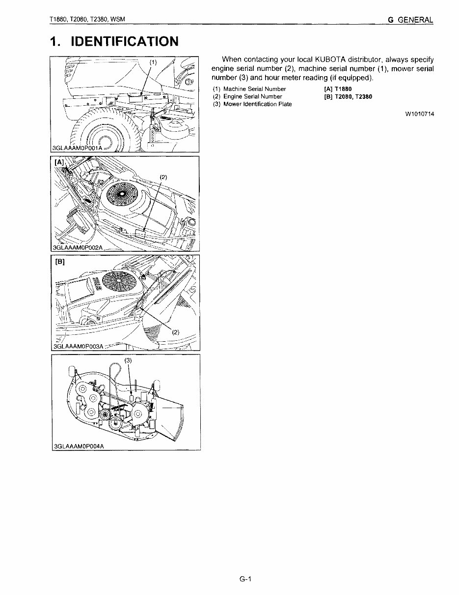
T1880, T2080, T2380, WSM G GENERAL 1. IDENTIFICATION When contacting your local KUBOTA distributor, always specify engine serial number (2), machine serial number (1). mower serial number (3) and hour meter reading (if equipped). (1) Machine Serial Number [A] T1880 (2) Engine Serial Number [8] 12080, T2380 (3) Mower Identification Plate W1010714 3GLAAAMOP004A G-1
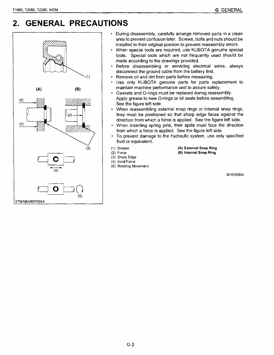
T1880, T2080, T2380, WSM G GENERAL 2. GENERAL PRECAUTIONS (1 ) (A) (8) (2) (2) (3) - (4) q 0 CJO (5) 3TMABABOP005A • During disassembly, carefully arrange removed parts in a clean area to prevent confusion later. Screws, bolts and nuts should be installed in their original position to prevent reassembly errors. • When special tools are required, use KUBOTA genuine special tools. Special tools which are not frequently used should be made according to the drawings provided. Before disassembling or servicing electrical wires, always disconnect the ground cable from the battery first. • Remove oil and dirt from parts before measuring. • Use only KUBOTA genuine parts for parts replacement to maintain machine performance and to assure safety. • Gaskets and O-rings must be replaced during reassembly. Apply grease to new O-rings or oil seals before assembling. See the figure left side. • When reassembling external snap rings or internal snap rings, they must be positioned so that sharp edge faces against the direction from which a force is applied. See the figure left side. • When inserting spring pins, their splits must face the direction from which a force is applied. See the figure left side. • To prevent damage to the hydraulic system, use only specified fluid or equivalent. (1) Grease (A) External Snap Ring (2) Force (8) Internal Snap Ring (3) Sharp Edge (4) Axial Force (5) Rotating Movement W1010904 G-2
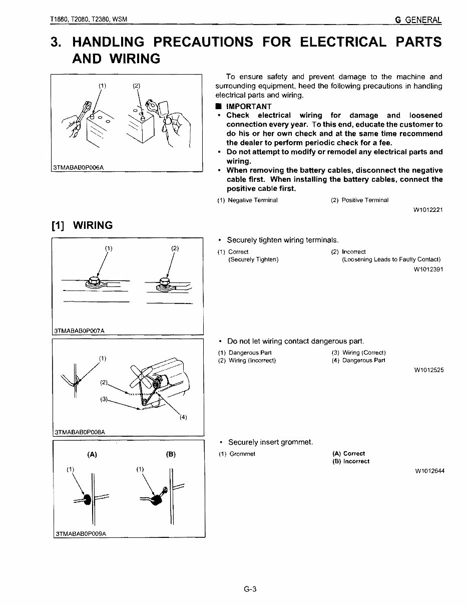
T1880. T2080. T2380, WSM G GENERAL 3. HANDLING PRECAUTIONS FOR ELECTRICAL PARTS AND WIRING (1 ) 3TMABABOPOO6A [1] WIRING (1) 3TMABABOP007A (4) 3TMABABOPOO8A (A) (8) (1~ (1 ) ~ 3TMABABOP009A To ensure safety and prevent damage to the machine and surrounding equipment. heed the following precautions in handling electrical parts and wiring . • IMPORTANT • Check electrical wiring for damage and loosened connection every year. To this end, educate the customer to do his or her own check and at the same time recommend the dealer to perform periodic check for a fee. • Do not attempt to modify or remodel any electrical parts and wiring. • When removing the battery cables, disconnect the negative cable first. When installing the battery cables, connect the positive cable first. (1) Negative Terminal (2) Positive Terminal W1012221 • Securely tighten wiring terminals. (1) Correct (2) Incorrect (Securely Tighten) (Loosening Leads to Faulty Contact) W1012391 • Do not let wiring contact dangerous part. (1) Dangerous Part (3) Wiring (Correct) (2) Wiring (Incorrect) (4) Dangerous Part W1012525 • Securely insert grommet. (1) Grommet (A) Correct (8) Incorrect W1012644 G-3
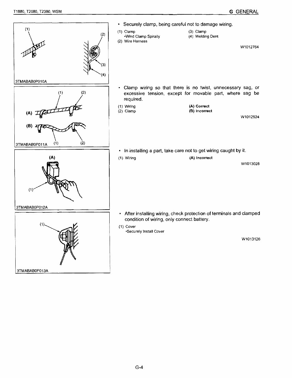
T1880, T2080, T2380, WSM G GENERAL (2) (4) 3TMABABOP010A (1 ) (2) (8) 3TMABABOP011A (1) (2) (A) (1) 3TMABABOP012A (1 ) 3TMABABOP013A • Securely clamp, being careful not to damage wiring. (1) Clamp (3) Clamp -Wind Clamp Spirally (4) Welding Dent (2) Wire Harness Wl012764 • Clamp wiring so that there is no twist. unnecessary sag. or excessive tension. except for movable part. where sag be required. (1) Wiring (A) Correct (2) Clamp (8) Incorrect W1012924 • In installing a part. take care not to get wiring caught by it. (1) Wiring (A) Incorrect W1013028 • After installing wiring. check protection of terminals and clamped condition of wiring, only connect battery. (1) Cover -Securely Install Cover W1013126 G-4
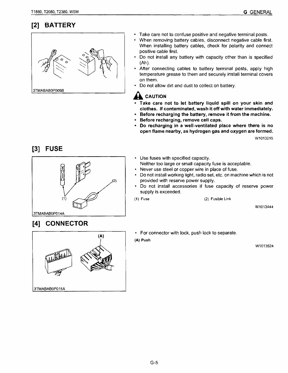
T1880, T2080, T2380, WSM G GENERAL [2] BATTERY 3TMABABOP006B [3] FUSE (1 ) 3TMABABOP014A (2) [4] CONNECTOR (A) 3TMABABOP015A • Take care not to confuse positive and negative terminal posts. • When removing battery cables. disconnect negative cable first. When installing battery cables, check for polarity and connect positive cable first. • Do not install any battery with capacity other than is specified (Ah). • After connecting cables to battery terminal posts. apply high temperature grease to them and securely install terminal covers on them. • Do not allow dirt and dust to collect on battery. A CAUTION • Take care not to let battery liquid spill on your skin and clothes. If contaminated, wash it off with water immediately. • Before recharging the battery, remove it from the machine. • Before recharging, remove cell caps. • Do recharging in a well-ventilated place where there is no open flame nearby, as hydrogen gas and oxygen are formed. W1013215 • Use fuses with specified capacity. Neither too large or small capacity fuse is acceptable. • Never use steel or copper wire in place of fuse. • Do not install working light, radio set, etc. on machine which is not provided with reserve power supply. • Do not install accessories if fuse capacity of reserve power supply is exceeded. (1) Fuse (2) Fusible Link W1013444 • For connector with lock. push lock to separate. (A) Push W1013524 G-5
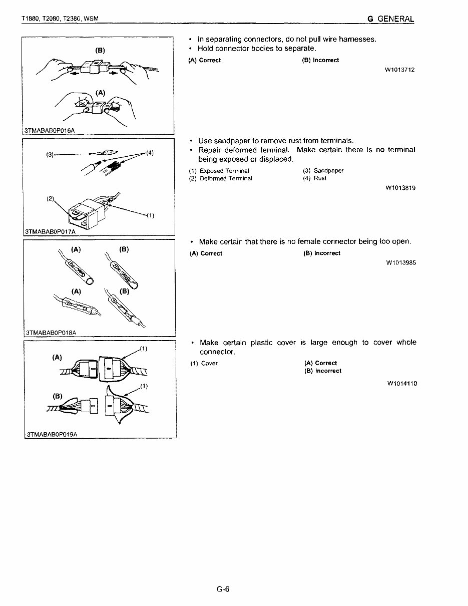
T1880, T2080, T2380, WSM G GENERAL • In separating connectors, do not pull wire harnesses. (8) • Hold connector bodies to separate. (A) Correct (8) Incorrect W1013712 3TMABABOP016A (3)1___ ~_'~(4J (1 ) ~ ,. ~ (8) 3TMABABOP018A ~(1) ~~ 3TMABABOP019A • Use sandpaper to remove rust from terminals. • Repair deformed terminal. Make certain there is no terminal being exposed or displaced. (1) Exposed Terminal (3) Sandpaper (2) Deformed Terminal (4) Rust W1013819 • Make certain that there is no female connector being too open. (A) Correct (8) Incorrect W1013985 • Make certain plastic cover is large enough to cover whole connector. (1) Cover (A) Correct (8) Incorrect W1014110 G-6
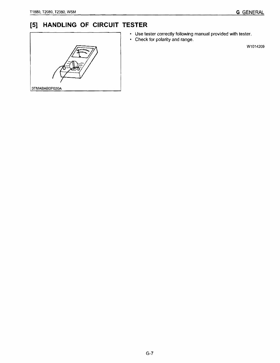
T1880, T2080, T2380, VVSM G GENERAL [5] HANDLING OF CIRCUIT TESTER • Use tester correctly following manual provided with tester. • Check for polarity and range. VV1014209 3TMABABOP020A G-7
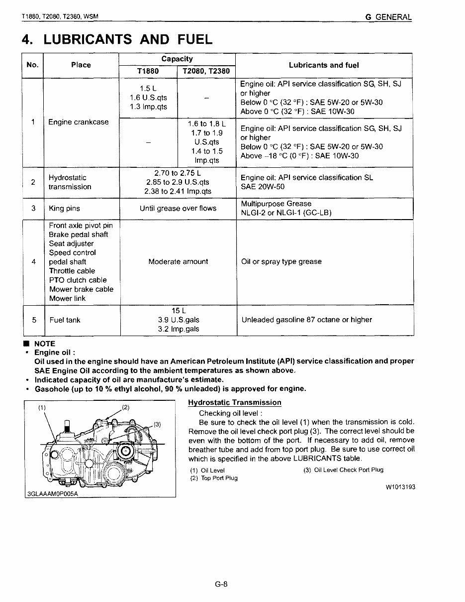
T1880, T2080, T2380, WSM G GENERAL 4. LUBRICANTS AND FUEL No. Place Capacity T1880 T2080, T2380 Lubricants and fuel 1.5 L 1.6 U.S.qts 1.3Imp.qts Engine oil: API service classification SG, SH. SJ or higher Below 0 °C (32 OF) : SAE 5W-20 or 5W-30 Above 0 °C (32 OF) : SAE 10W-30 1 Engine crankcase - 1.6 to 1.8 L 1.7 to 1.9 U.S.qts 1.4 to 1.5 Imp.qts Engine oil: API service classification SG, SH, SJ or higher Below 0 °C (32 OF) : SAE 5W-20 or 5W-30 Above -18 DC (0 OF) : SAE 10W-30 2 Hydrostatic transmission 2.70 to 2.75 L 2.85 to 2.9 U.S.qts 2.38 to 2.41 Imp.qts Engine oil: API service classification SL SAE 20W-50 3 King pins Until grease over flows Multipurpose Grease NLGI-2 or NLGI-1 (GC-LB) 4 Front axle pivot pin Brake pedal shaft Seat adjuster Speed control pedal shaft Throttle cable PTO clutch cable Mower brake cable Mower link Moderate amount Oil or spray type grease 5 Fuel tank 15 L 3.9 U.S.gals 3.2 Imp. gals Unleaded gasoline 87 octane or higher • NOTE • Engine oil : Oil used in the engine should have an American Petroleum Institute (API) service classification and proper SAE Engine Oil according to the ambient temperatures as shown above. • Indicated capacity of oil are manufacture's estimate. • Gasohole (up to 10 % ethyl alcohol, 90 % unleaded) is approved for engine. Hydrostatic Transmission Checking oil level : Be sure to check the oil level (1) when the transmission is cold. Remove the oil level check port plug (3). The correct level should be even with the bottom of the port. If necessary to add oil, remove breather tube and add from top port plug. Be sure to use correct oil which is specified in the above LUBRICANTS table. (1) Oil Level (3) Oil Level Check Port Plug (2) Top Port Plug W1013193 3GLAAAMOP005A G-8
The Kubota T1880 T2080 T2380 Lawn Tractor Workshop Service Repair Manual is a comprehensive guide for maintaining and repairing your Kubota T1880 T2080 T2380 Lawn Tractor. With 440 pages, this manual provides detailed instructions for both professional mechanics and DIY enthusiasts. It covers various aspects including the general information, engine, hydrostatic transaxle, brakes, front axle, steering, fender and lift system, PTO, electrical system, mower, and more.
Whether you need to print the entire manual or specific pages, this manual is designed to assist you in keeping your vehicle in optimal working condition. It includes detailed substeps, notes, cautions, warnings, numbered instructions, illustrations, drawings, photos, and a table of contents for easy navigation. Additionally, it offers troubleshooting and electrical service procedures along with wiring diagrams for diagnosing and repairing electrical system issues.
The manual is available in .PDF format, compatible with all PC-based Windows operating systems and Mac. It can be saved to your hard drive or burned to a CD-ROM for easy access. There's no need to wait for shipping as it is instantly accessible after purchase. The language of the manual is English, and it can be printed without any restrictions. Adobe Reader is required for viewing the manual.
Get your Kubota T1880 T2080 T2380 Lawn Tractor Workshop Service Repair Manual now and ensure the longevity and performance of your vehicle.