Kubota G1900 Tractor Workshop Repair Service Manual
What's Included?
Lifetime Access
Fast Download Speeds
Online & Offline Access
Access PDF Contents & Bookmarks
Full Search Facility
Print one or all pages of your manual
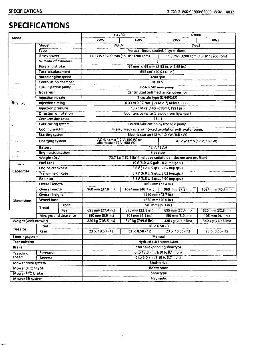
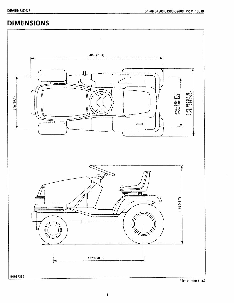
SPECIFICATIONS G1700·G1800·G1900·G2000 MM,10832 SPECIFICATIONS 61700 61800 Model 2WS 4WS 2WS I 4WS Model D662-L D662 Type Vertical,liquid cooled, 4-cycle, diesel Gross power 11.1 kW 13200 rpm (15 HP 13200 rpm) 11.9 kW 13200 rpm (16 HP 13200 rpm) Number of cylinders 3 Bore and stroke 64 mm x 68 mm (2.52 in. x 2.68 in.) Total displacement 655 cm 3 (40.03 cu.!n.) Rated engine speed 3200 rpm Combustion chamber NTVCS -- ,- Fuel injection pump Bosch MD mini pump Governor Centrifugal ball mechanical governor .. Injection nozzle Throttle type (DN4PD62) '~ngin_e. Injection timing 0.33 toO.37 rad. (19 to 21·) before T.D.C. Injection pressure 13.73 MPa (140 kgf/cm2, 1991 psi) Direction of rotation Counterclockwise (viewed from flywheel) _.' ~ Compression ratio 23: 1 .. Lubricating system Forced lubrication by trochoid pump Cooling system Pressurized radiator, forced circulation with water pump Starting system Electric starter (12 V, 1.0 kW 10.8 kW) .. Charging system ACdynamo (12 V, 1S0W)or alternator (12 V, 480 W) ACdynamo(12 V, 150W) Battery 12V,45AH - -. Engine stop system Key stop ,~ " Weight (Dry) 73.7 kg (162.5Ibs) [includes radiator, air cleaner and muffler] .-~ -. Fuel tank 191 (S.O U.S.gals., 4.2Imp.gals.) Capacities Engine crankcase 3.0 I (3.2 U.S.qu., 2.64 Imp.qU.) Transmission case 5.71 (6.0 U.S.qu., S.02Imp.qU.) Radiator 3.31 (3.S U.S.qu., 2.90 Imp.qu.) Overall length 1865 mm (73.4 in.) Overall width 960 mm (37.8 in.) 1034 mm (40.7 in.) 960 mm (37.8 in.) 1034 mm (40.7 in.) Overall height 1110 mm (43.7 in.) Dimensions Wheel base 1270 mm (50.0 in.) Tread I Front 740 mm (29.1 in.) I Rear 695 mm (27.4 in.) 820 mm (32.3 in.) 69S mm (27.4 in.) 820 mm (32.3 in.) Min. ground clearance lS0 mm (5.9 in.) 105 mm (4.1 in.) 150 mm (S.9 in.) 10Smm(4.1 in.) Weight (with mower) 320 kg (705.Slbs) 340 kg (749.6Ibs) 320 kg (705.S Ibs) 340 kg (749.6Ibs) Front 16 x 6.S0-8 Tire size Rear 23 x 10.S0-12 23 x 8.S0-12 23 x 10.S0-12 23 x 8.S0-12 Steering system Manual Transmission Hydrostatictransmission Brake Internal expanding shoe type Traveling Forward Ot013.0km/h(Ot08.1 mph) speed Reverse Oto 6.0 km Ih (0 to 3.7 mph) Mower drive system Shaft drive Mower clutch type Belt tension Mower PTO brake Shoe type Mower lift system Hydraulic
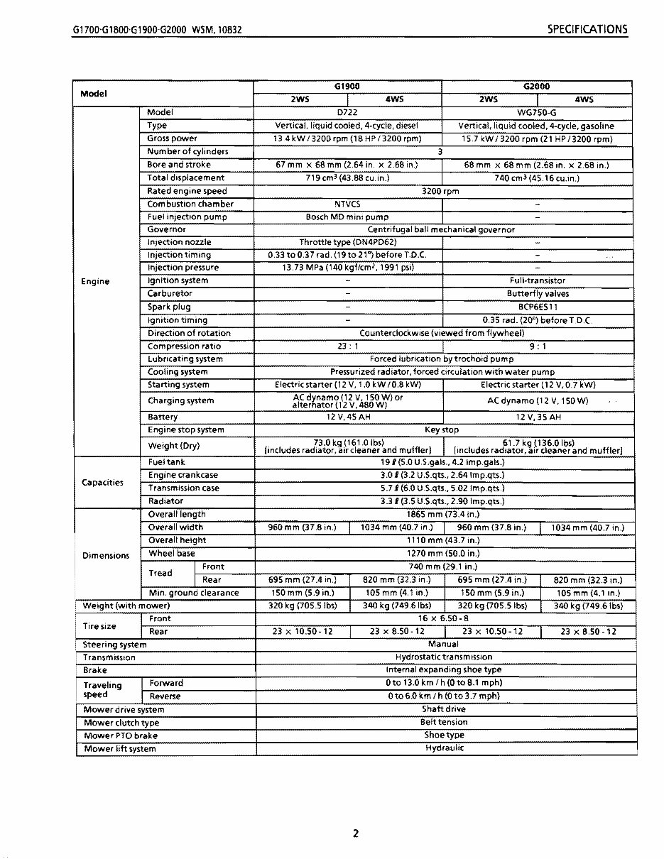
G1700·G1800·G1900·G2000 WSM,10832 SPECifiCATIONS G1900 G2000 Model 2WS 4WS 2WS I 4WS Model D722 WG750-G Type ,liquid cooled, 4-cycle, diesel Vertical, liquid cooled, 4·cycle, gasoline Gross power 13.4 kW 13200 rpm (18 HP 13200 rpm) 15.7 kW 13200 rpm (21 HP 13200 rpm) Number of cylinders 3 Bore and stroke 67 mm x 68 mm (2.64 in. x 2.68 in.) 68 mm x 68 mm (2.68 in. x 2.68 in.) Total displacement 719 cm 3 (43.88 cu.in.) 740 cm 3 (45.16 cu.in.) Rated engine speed 3200 rpm Combustion chamber NTVCS Fuel injection pump Bosch MD mini pump - Governor Centrifugal ball mechanical governor ~onnoZZle Throttle type (DN4PD62) Ion timing 0.33 to 0.37 rad. (19to 21"') before T.D.C. - Injection pressure 13.73 MPa (140 kgf/cm2, 1991 psi) - Engine Ignition system - Full-transistor Carburetor - Butterfly valves Spark plug - BCP6ESll Ignition timing - 0.35 rad. (20°) before T.D.C. Direction of rotation Counterclockwise (viewed from flywheel) Compression ratio 23: 1 9: 1 Lubricating system Forced lubrication by trochoid pump Cooling system Pressurized radiator, forced circulation with water pump system (12 V, 1.0 kW 10.8 leW) Electric starter (12 V, 0.7 kW) g system ACdynamo(12V, 150W)or alternator (12 V, 480W) ACdynamo(12 V,ls0W) Battery 12 V,4sAH 12V,35AH Engine stop system Key stop Weight (Dry) 73.0 kg (161.0 Ibs) [includes radiator, air cleaner and muffler] 61.7 kg (136.0 Ibs) [includes radiator, air cleaner and muffler] Fueltank 191 (5.0 U.S.gals., 4.2 Imp.gals.) Capacities Engine crankcase 3.0 I (3.2 U.S.qts., 2.64lmp.qts.) Transmission case 5.71 (6.0 U.S.qts., 5.02 Imp.qts.) Radiator 3.31 (3.5 U.S.qts., 2.90 Imp.qts.) Overall length 1865 mm (73.4 in.) Overall width 960 mm (37.8 in.) 1034 mm (40.7 in.) 960 mm (37.8 in.) 1034 mm (40.7 in.) Overall height 1110 mm (43.7 in.) Dimensions Wheel base 1270 mm (50.0 in.) Tread I Front 74Omm(29.1 in.) I Rear 695 mm (27.4 in.) 820mm~ 695 mm (27.4 in.) 820 mm (32.3 in.) Min. ground clearance 150mm(5.9in.) 105mm 150 mm (5.9 in.) 105 mm (4.1 in.) Weight (with mower) 320 kg (70s.slbs) 340 kg (7 320 kg (705.5 Ibs) 340 kg (749.6Ibs) ~ 16 x 6.50-8 Tire size 23 x 10.50·12 23 x 8.50·12 23 x 10.50-12 23 x 8.50 -12 Steering system Manual Transmission Hydrostatic transm ission Brake Internal expanding shoe type I Traveling Forward Oto 13.0 km I h (O to 8.1 mph) • speed Reverse Oto 6.0 km I h (0 to 3.7 mph) Mower drive system Shaft drive Mower clutch type Belt tension Mower PTO brake Shoe type Mower lift system Hydraulic 2
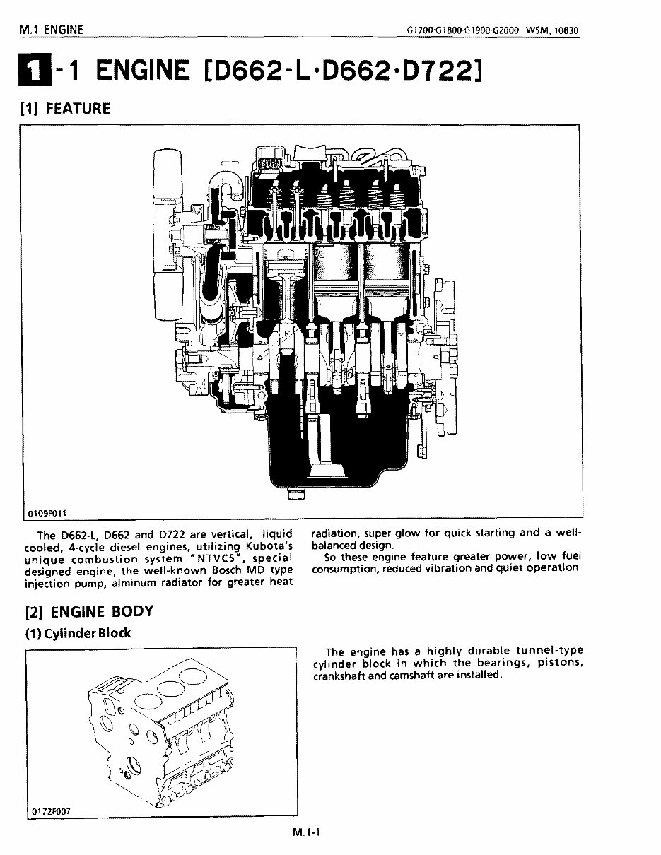
M.1 ENGINE G1700·G1800·G1900·G2000 WSM.10830 0-1 ENGINE [D662-L'D662'0722] [1] FEATURE 0109F011 The 0662-L, 0662 and 0722 are vertical, liquid radiation, super glow for quick starting and a well- cooled, 4-cycle diesel engines, utilizing Kubota's balanced design. unique combustion system "NTVCS" I special So these engine feature greater power, low fuel consumption, reduced vibration and quiet operation. designed engine, the well-known Bosch MO type injection pump, alminum radiator for greater heat [2] ENGINE BODY (1) Cylinder Block 0172FO07 The engine has a highly durable tunnel-type cylinder block in which the bearings, pistons, crankshaft and camshaft are installed. M.l-l
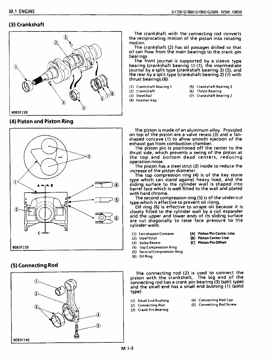
M.1 ENGINE G1700-G1800-G1900·G2000 WSM.10830 (3) Crankshaft B083F238 (4) Piston and Piston Ring B083F239 (5) Connecting Rod The crankshaft with the connecting rod converts the reciprocating motion of the piston into rotating motion. The crankshaft (2) has oil passages drilled so that oil can flow from the main bearings to the crank pin bearings_ The front journal is supported by a sleeve type bearing (crankshaft bearing 1) (1), the intermediate journal by a split type (crankshaft bearing 3) (5), and the rear by a split type (crankshaft bearing 2) (7) with thrust bearings (6). (1) (2) (3) (4) Crankshaft Bearing 1 Crankshaft Steel Ball Feather Key (5) (6) (7) Crankshaft Bearing 3 Thrust Bearing Crankshaft Bearing 2 The piston is made of an aluminum alloy. Provided on top of the piston are a valve recess (3) and a fan- shaped concave (1) to allow smooth ejection of the exhaust 9as from combustion chamber. The piston pin is positioned off the center to the thrust side, which prevents a swing of the piston at the top and bottom dead centers, reducing operation noise. The piston has a steel strut (2) inside to reduce the increase of the piston diameter. The top compression ring (4) is of the key stone type which can stand against heavy load, and the sliding surface to the cylinder wall is shaped into barrel face which is well fitted to the wall and plated with hard chrome. The second compression ring (5) is of the under-cut type which is effective to prevent oil rising. Oil ring (6) is effective to scrape oil because it is closely fitted to the cylinder wall by a coil expander and the upper and lower ends of its sliding surface are cut diagonally to raise face pressure to the cyli nder walls. (1) Fan-shaped Concave tA) Piston Pin Center Line (2) Steel Strut (8) Piston Center line (3) Valve Recess (C) Piston Pin Offset (4) Top Compression Ring (5) Second Compression Ring (6) Oil Ring The connecting rod (2) is used to connect the piston with the crankshaft. The big end of the connecting rod has a crank pin bearing (3) (split type) and the small end has a small end bushing (1) (solid type). (1) Small End Bushing (4) Connecting Rod Cap (2) Connecting Rod (5) Connecting Rod Screw (3) Crank Pin Bearing BOB3F240 M.1-3
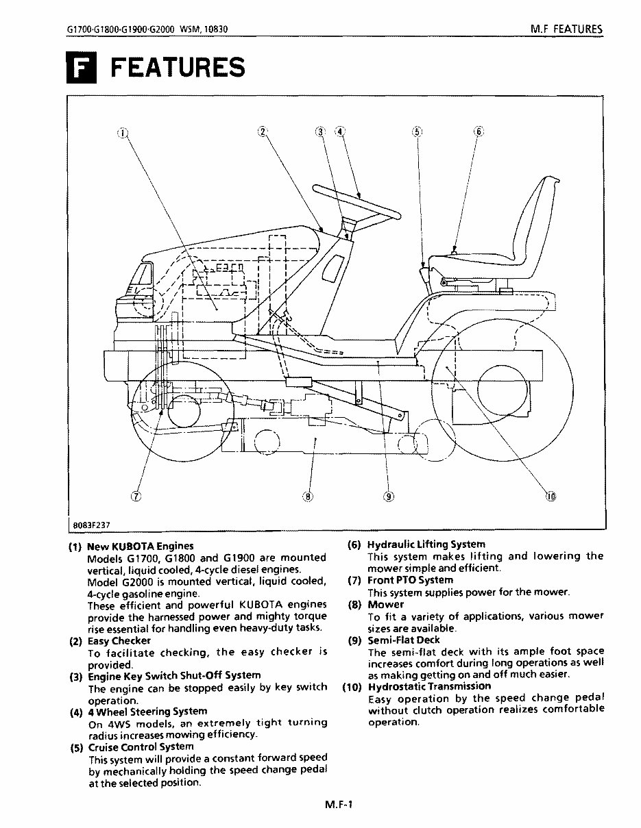
Gt700'G1800'G1900'G2000 WSM,10830 M.F FEATURES Ii FEATURES BOB3F237 (1) New KUBOTA Engines Models G1700, G1800 and G1900 are mounted vertical, liquid cooled, 4-cycle diesel engines. Model G2000 is mounted vertical, liquid cooled, 4-cycle gasoline engine. These efficient and powerful KUBOTA engines provide the harnessed power and mighty torque rise essential for handling even heavy-duty tasks. (2) Easy Checker To facilitate checking, the easy checker is provided. (3) Engine Key Switch Shut·Off System The engine can be stopped easily by key switch operation. (4) 4 Wheel Steering System On 4WS models, an extremely tight turning radius increases mowing efficiency. (5) Cruise Control System This system will provide a constant forward speed by mechanically holding the speed change pedal at the selected position. (6) Hydraulic Lifting System This system makes lifting and lowering the mower simple and efficient. (7) Front PTO System This system supplies power for the mower. (8) Mower To fit a variety of applications, various mower sizes are available. (9) Semi-Flat Deck The semi-flat deck with its ample foot space increases comfort during long operations as well as making getting on and off much easier. (10) Hydrostatic Transmission Easy operation by the speed change pedal without clutch operation realizes comfortable operation. M.F-1
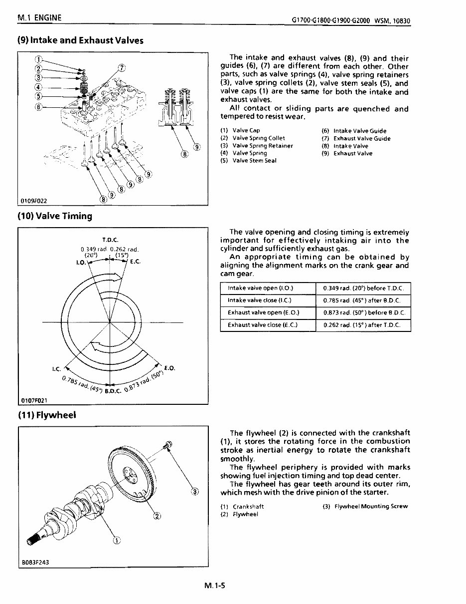
@ (,4 .. ~~ : '0" @(r'Q)'l'-< .~ . ~ ~;::--i.L ~~ M.1 ENGINE G1700'G 1800'G 1900'G2000 WSM. 10830 T.O.C. 0349 rad 0.262 rad. (20°) (15°) 1.0. E.e. 0107F021 Intake valve open (1.0.) 0.349 rad. (20°) before 1.0.( Intake valve dose (I.C) 0.785 rad. (45·) after B.D.C Exhaust valve open (E.O.) 0.873 rad. (50·) before B.D.C Exhaust valve close (E.C.) 0.262 rad. (15 0 ) after T.D.C (11) Flywheel B083F243 (9) Intake and Exhaust Valves I""" ,~r '''''''''':' ':>r ~~.~/..-< .-/~ n I 0109F022 (10) Valve Timing The intake and exhaust valves (8). (9) and their guides (6), (7) are different from each other. Other parts. such as valve springs (4). valve spring retainers (3). valve spring collets (2), valve stem seals (5), and valve caps (1) are the same for both the intake and exhaust valves. All contact or sliding parts are quenched and tempered to resist wear . (1 ) (2) (3) (4) (5) Valve Cap Valve Spring Collet Valve Spring Retainer Valve Spring Valve Stem Seal (6) (7) (8) (9) Intake Valve Guide Exhaust Valve Guide Intake Valve Exhaust Valve The valve opening and closing timing is extremely important for effectively intaking air into the cylinder and sufficiently exhaust gas. An appropriate timing can be obtained by aligning the alignment marks on the crank gear and cam gear. ~ The flywheel (2) is connected with the crankshaft (1). it stores the rotating force in the combustion stroke as inertial energy to rotate the crankshaft smoothly. The flywheel periphery is provided with marks showing fuel injection timing and top dead center. The flywheel has gear teeth around its outer rim. which mesh with the drive pinion of the starter. (1) Cranksnaft (3) Flywheel Mounting Screw (2) Flywheel M.l-S
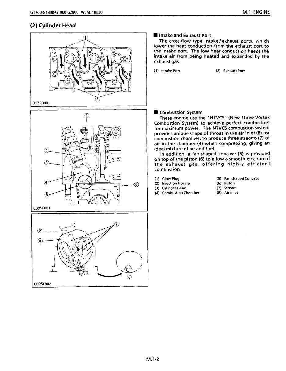
G1700'G1800'G1900'G2000 WSM, 10830 M.l ENGINE (2) Cylinder Head C095FOO2 0172FOO8 C095FOOl • Intake and Exhaust Port The cross-flow type intake I exhaust ports, which lower the heat conduction from the exhaust port to the intake port. The low heat conduction keeps the intake air from being heated and expanded by the exhaust gas. (1) Intake Port (2) Exhaust Port • Combustion System These engine use the HNTVCS" (New Three Vortex Combustion System) to achieve perfect combustion for maximum power. The NTVCS combustion system provides unique shape of throat in the air inlet (8) for combustion chamber, to produce three streams (7) of air in the chamber (4) when compressing, giving an ideal mixture of air and fuel. In addition, a fan-shaped concave (5) is provided on top of the piston (6) to allow a smooth ejection of the exhaust gas, offering highly efficient combustion. (1) Glow Plug (5) Fan-shaped Concave (2) Injection Nozzle (6) Piston (3) Cylinder Head (7) Stream (4) Combustion Chamber (8) Air Inlet M.1-2
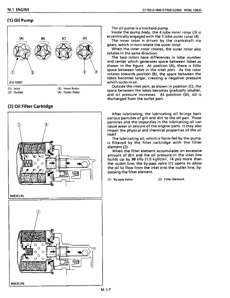
M.1 ENGINE G1700·G1800·G1900·G2000 WSM,10830 (1) Oil Pump 0321FOO7 181 (C] (1) Inlet (2) Outlet (2) Oil Filter Cartridge (3) Inner Rotor (4) Outer Rotor B083F245 The oil pump is a trochoid pump. Inside the pump body, the 4 lobe inner rotor (3) is eccentrically engaged with the 5 lobe outer rotor (4). The inner rotor is driven by the crankshaft via gears, which in turn rotate the outer rotor. When the inner rotor rotates, the outer rotor also rotates in the same direction. The two rotors have differences in lobe number and center which generates space between lobes as shown in the figure. At position (A), there is little space between lobes in the inlet port. As the rotor rotates towards position (8), the space between the lobes becomes larger, creating a negative pressure which sucks in oil. Outside the inlet port, as shown in position (C), the space between the lobes becomes gradually smaller, and oil pressure increases. At position (0), oil is discharged from the outlet port. After lubricating, the lubricating oil brings back various particles of grit and dirt to the oil pan. Those particles and the impurities in the lubricating oil can cause wear or seizure of the engine parts. It may also impair the physical and chemical properties of the oil itself. The lubricating oil, which is force-fed by the pump, is filtered by the filter cartridge with the filter element (2). When the filter element accumulates on excessive amount of dirt and the oil pressure in the inlet line builds up by 98 kPa (1.0 kgflcm2, 14 psi) more than the outlet line, the by-pass valve (1) opens to allow the oil to flow from the inlet into the outlet line, by- passing the filter element. (1) By-pass Valve (2) Filter Element B083F246 M.1-7
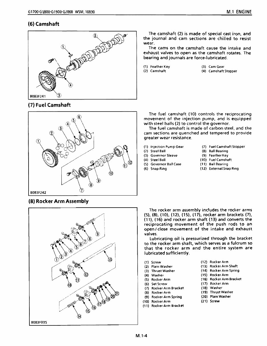
G1700'G\800'G1900'GlOOO WSM,10830 M.l ENGINE (6) Camshaft B083F241 (7) Fuel Camshaft B083F242 (8) Rocker Arm Assembly The camshaft (2) is made of special cast iron, and the journal and cam sections are chilled to resist wear. The cams on the camshaft cause the intake and exhaust valves to open as the camshaft rotates. The bearing and journals are force-lubricated. (1) Feather Key (3) Cam Gear (2) Camshaft (4) Camshaft Stopper The fuel camshaft (10) controls the reciprocating movement of the injection pump, and is equipped with steel balls (2) to control the governor. The fuel camshaft is made of carbon steel, and the cam sections are quenched and tempered to provide greater wear resistance. (1) Injection Pump Gear (7) Fuel Camshaft Stopper (2) Steel Ball (8) Ball Bearing (3) Governor Sleeve (9) Feather Key (4) Steel Ball (10) Fuel Camshaft (5) Governor Ball Case (11 ) Ball Bearing (6) Snap Ring (12) External Snap Ring The rocker arm assembly includes the rocker arms (5), (8), (10), (12), (15), (17), rocker arm brackets (7), (11), (16) and rocker arm shaft (13) and converts the reciprocating movement of the push rods to an open I close movement of the intake and exhaust valves. lubricating oil is pressurized through the bracket to the rocker arm shaft, which serves as a fulcrum so that the rocker arm and the entire system are Iubricated sufficiently. (1 ) Screw (12) Rocker Arm (2) Plain Washer (13) Rocker Arm Shaft (3) Thrust Washer (14) Rocker Arm Spring (4) Washer (IS) Rocker Arm (5) Rocker Arm (16) Rocker Arm Bracket (6) Set Screw (17) Rocker Arm (7) Rocker Arm Bracket (18) Washer (8) Rocker Arm (19) Thrust Washer (9) Rocker Arm Spring (20) Plain Washer (10) Rocker Arm (21 ) Screw (11 ) Rocker Arm Bracket B083F03S M.l-4
This workshop service manual for the Kubota G1900 Tractor is designed for mechanical technicians familiar with service procedures for BRP products. It covers repair and overhaul of Kubota G1900 Tractor cars, assuming the technician is well-versed in general automobile practices. The manual includes instructions on components manufactured for Kubota G1900 Tractor, as well as repairs of proprietary components with instructions from respective manufacturers. It provides reliable information and emphasizes particular information denoted by the wording and symbols: WARNING, CAUTION, NOTE.
The manual offers diagnostic and repair procedures, making it useful for both professional mechanics and DIY enthusiasts. It also emphasizes the importance of safety equipment and precautions when working on the Kubota G1900 Tractor, including the use of a torque wrench and special tools for adjustments or repairs. The manual aims to help users get the best value from their Kubota G1900 Tractor and provides specifications and procedures available in an authorized Kubota G1900 Tractor dealer service department.
This comprehensive service manual contains instructions for tune-ups, maintenance, removal & install procedures, assemblies & disassemblies, fuel system, ignition, lubrication system, exhaust, electrical system, body, and more extensive repairs involving engine and transmission disassembly for the Kubota G1900 Tractor.
It is an electronic delivery via email and is printable in English. The content depicts parts and/or procedures applicable to the particular product at the time of writing. The manual is a valuable resource for anyone intending to do maintenance and repair on their Kubota G1900 Tractor, providing detailed information and procedures for routine maintenance and servicing.
Diagnostic and repair procedures for Kubota G1900 Tractor
Instructions on components and proprietary parts
Safety equipment and precautions emphasized
Specifications and procedures available in an authorized dealer service department
Comprehensive instructions for various maintenance and repair procedures
For those looking to save time and money by performing simpler jobs themselves, this manual provides the necessary guidance. It also includes extensive information on general maintenance tasks, making it a valuable resource for maintaining the Kubota G1900 Tractor in optimal condition.
Fast and free electronic delivery via email
Language: English
Printable: Yes
File Format: .PDF
Overall, this workshop service manual for the Kubota G1900 Tractor is a comprehensive resource for both professional mechanics and DIY enthusiasts, providing detailed instructions and procedures for maintenance, servicing, and repairs.
Recently Viewed
5,521,897Happy Clients
2,594,462eManuals
1,120,453Trusted Sellers
15Years in Business
Price:
Actual Price:
Kubota G1900 Tractor Workshop Repair Service Manual