

Jacobsen LF-3400 & LF-3800 Repair Service Manual
What's Included?
Fast Download Speeds
Online & Offline Access
Access PDF Contents & Bookmarks
Full Search Facility
Print one or all pages of your manual
SERVICE & REPAIR
INSTRUCTIONS
LF-3400 & LF-3800
LF-3400 2 Wheel Drive LF-3800 2 Wheel Drive
Product No. 67839 Product No. 67837
Product No. 67869 Product No. 67866
LF-3400 4 Wheel Drive LF-3800 4 Wheel Drive
Product No. 67840 Product No. 67838
Product No. 67869 Product No. 67867
LF-3400 4 Wheel Drive Turbo Engine
Product No. 67889
Includes Attachments
and Product Options
Litho in U.S.A. 5/01
WARNING: If incorrectly used this machine can cause severe injury. Those who
use and maintain the machine should be trained in its proper use, warned of its
dangers and should read the entire manual before attempting to set up, operate,
adjust or service the machine.
!
Copyright 2001 Textron Golf, Turf & Specialty Products
“All rights reserved, including the right to reproduce this
material or portions thereof in any form.”
Publication Registration
Information, specifications, illustrations and procedures in this
manual are based on information in effect at the time of publication.
Product improvements and changes due to advancements of product
design may not be included in this manual. This manual is reviewed
and updated as required to include changes and product improve-
ments. By returning the completed Registration below TGTSP will
notify you when an update is available.
Send Registration to:
Textron Golf,Turf & Specialty Products
1721 Packard Avenue
Racine, WI 53403-2564
Attn: Product and Service Tr aining
Litho Date:
Company Name __________________________________________
Your Name ______________________________________________
Your E-mail Address ______________________________________
Address ________________________________________________
City, State __________________________________ Zip ________
Register Your CD
Use the registration
on back of tray card.
CD-SRI-3400/3800
GOLF , TURF & SPECIALTY PRODUCTS

1
14
2
3
4
5
6
7
8
9
10
11
12
13
INTRODUCTION
CONTROLS
ENGINE
DRIVE TRAIN
BRAKE SYSTEM
STEERING
WHEELS & TIRES
HYDRAULICS
CHASSIS
ELECTRICAL SYSTEM
PREVENTIVE MAINTENANCE
ATTACHMENTS
OPTIONS
MISCELLANEOUS

1
1A. General Information . . . . . . . . . . . . . . . . . . . . . . . . . . . . . . . . . . . . . . . . . . . . . . . . . . . . . . . . . . . . 1A-1
Contents . . . . . . . . . . . . . . . . . . . . . . . . . . . . . . . . . . . . . . . . . . . . . . . . . . . . . . . . . . . . . . . . . . . . . . . 1A-1
Registration . . . . . . . . . . . . . . . . . . . . . . . . . . . . . . . . . . . . . . . . . . . . . . . . . . . . . . . . . . . . . . . . . . . . . 1A-1
Index Numbers . . . . . . . . . . . . . . . . . . . . . . . . . . . . . . . . . . . . . . . . . . . . . . . . . . . . . . . . . . . . . . . . . . 1A-1
Replacement Parts . . . . . . . . . . . . . . . . . . . . . . . . . . . . . . . . . . . . . . . . . . . . . . . . . . . . . . . . . . . . . . 1A-1
Serial Numbers . . . . . . . . . . . . . . . . . . . . . . . . . . . . . . . . . . . . . . . . . . . . . . . . . . . . . . . . . . . . . . . . . 1A-2
General Cleaning . . . . . . . . . . . . . . . . . . . . . . . . . . . . . . . . . . . . . . . . . . . . . . . . . . . . . . . . . . . . . . . 1A-2
Safety . . . . . . . . . . . . . . . . . . . . . . . . . . . . . . . . . . . . . . . . . . . . . . . . . . . . . . . . . . . . . . . . . . . . . . . . . . 1A-2
Torque Values . . . . . . . . . . . . . . . . . . . . . . . . . . . . . . . . . . . . . . . . . . . . . . . . . . . . . . . . . . . . . . . . . . 1A-2
Torque Specifications . . . . . . . . . . . . . . . . . . . . . . . . . . . . . . . . . . . . . . . . . . . . . . . . . . . . . . . . . . . 1A-3
Standard SAE Grade #5 Screws . . . . . . . . . . . . . . . . . . . . . . . . . . . . . . . . . . . . . . . . . . . . . . 1A-3
Metric . . . . . . . . . . . . . . . . . . . . . . . . . . . . . . . . . . . . . . . . . . . . . . . . . . . . . . . . . . . . . . . . . . . . . . . 1A-3
SECTION 1
INTRODUCTION

CONTENTS
This manual contains repair instructions for major trac-
tor components, attachments and options. The Table of
Contents at the start of each section lists contents of
that section. Sections are identified by tabs in the right
hand margin.
This manual is to be used in conjunction with the Oper-
ator’s Manual and Parts Catalog.
Normal maintenance, adjustment, and operating proce-
dures are also covered in the user Operator’s Manual
and are only included where appropriate in this Service
and Repair Manual.
Engine repair is not covered in this manual. Refer to
the appropriate engine manufacturer’s instructions for
engine service and repair.
This manual includes all removal, disassembly, inspec-
tion, repair, reassembly, installation, adjustment, and
testing procedures. If you, as user of this machine, do
not consider yourself or your repair facilities capable
of a given procedure, please consult your dealer or
distributor.
Information, specifications, illustrations, and procedures
in this manual are based on information in effect at the
time this manual was published. Improvements and
product changes due to continual advancements of the
product design may cause changes to your product
that may not be included in this manual. Each manual
is reviewed and updated as required to include changes
and product improvements.
Read each section completely before proceeding with
specific repairs in that section. You will minimize errors
by understanding what you will be doing and how the
component relates to others in its system. Lists of
repair tools and materials for each section of the man-
ual are given at the start of that section.
The designations L.H. (left hand) and R.H. (right hand)
used throughout this manual refer to the operator’s left
or right when sitting in the normal operating position.
REGISTRATION
A registration card is provided in the back of this man-
ual (bottom portion of page). Fill out the card, remove
and mail immediately upon opening the manual for the
first time.
The registration entitles you to receive manual updates
for a period of two years. Updates are sent free of
charge.
NOTE
Only the original registration card will be accept-
ed. Photo copies, cards from other manuals, sug-
gestion cards, or any facsimile are not acceptable
and will not constitute a registration.
INDEX NUMBERS
Illustrations showing removal, disassembly, reassembly
and installation may have index numbers to call out the
sequence of procedure.
Where the sequence of procedure is not important or
self-evident (eg. linkages, hoses, clamps, etc.) index
numbers are not included.
Repair procedures for items not subject to wear (eg.
panels, brackets, frames) are not included in this man-
ual except for the general procedures given below.
Exercise common sense during disassembly or reas-
sembly; remove only the items required to accomplish
necessary repair or service.
REPLACEMENT PARTS
Use the appropriate Parts Catalog when ordering re-
placement parts. Follow installation instructions shipped
with service parts or kits. When ordering parts, always
give the serial number and product number of your
machine as well as quantity, part number and descrip-
tion of the parts needed.
To eliminate error and speed delivery:
1. Write your NAME and ADDRESS on your order
plainly.
2. Explain WHERE and HOW to make shipment.
3. Give PRODUCT NUMBER, NAME and SERIAL
NUMBER that is stamped on the NAME and SERI-
AL PLATE of your product.
4. Order by QUANTITY DESIRED, the PART NUM-
BER and the DESCRIPTION OF PART.
5. Send your order to or visit your nearest dealer or
distributor.
6. INSPECT ALL SHIPMENTS ON RECEIPT. If any
parts are damaged or missing, file a claim with the
carrier before accepting.
7. Do not return material to your dealer or distributor
without a letter of explanation. Make a list of all
returned parts, show your name and address, and
include it with the shipment. TRANSPORTATION
CHARGES MUST BE PREPAID.
SECTION 1A. GENERAL INFORMATION
1A-1
1A
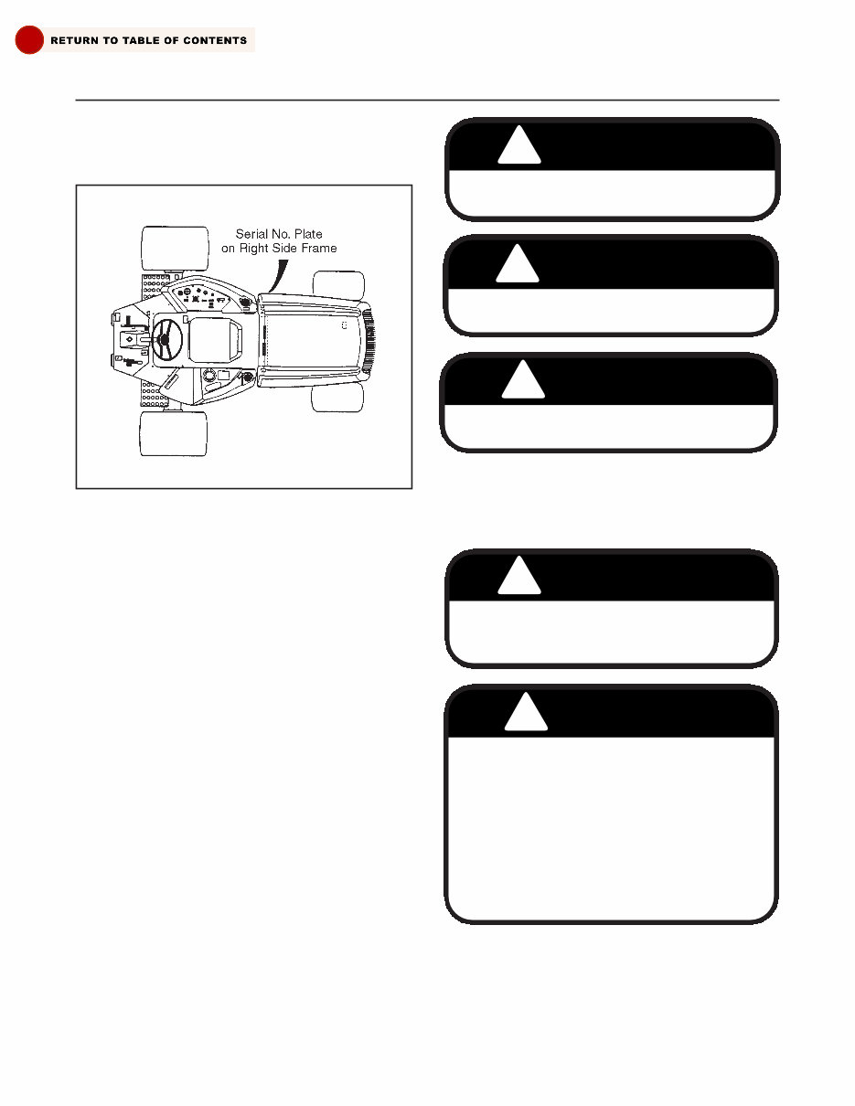
SERIAL NUMBERS
See Figure 1A-1 for location of tractor assembly serial
number.
GENERAL CLEANING
Improper cleaning and lubrication of your machine
results in many equipment failures. Before any repairs
are undertaken, thoroughly clean the exterior of the
component to be removed.
Use a clean surface to lay out parts being removed.
Keep lubricants clean and cover containers not being
used. Plug or cap all hydraulic lines and ports to hy-
draulic components immediately after disconnecting.
SAFETY
Safety should always be the rule when working on or
with machinery. Always use safe practices and com-
mon sense when using hand or power tools. Use the
suggested procedures in this manual when working
with the tractor.
Throughout this manual signal words will be used to
highlight special procedures. The signal words and
their meaning are as follows:
NOTE
Any procedure needing special care when per-
forming a procedure.
Decals on the machine denote cautions, warnings and
dangers. These cautions, warnings and danger decals
must be on the machine at all times. If they become
worn, torn or painted over, new decals should be in-
stalled as shown in Section 14 of this manual.
TORQUE VALUES
Torque values are given in the following “Torque Speci-
fication Chart”. Special torque values are called out on
illustrations and text throughout this manual.
SECTION 1A. GENERAL INFORMATION
1A-2
Figure 1A-1. Serial Number Location
! CAUTION
Hazards or unsafe practices which could result
in personal injury or product or property damage.
! WARNING
Hazards or unsafe practices which could result
in severe personal injury or death.
! DANGER
Imminent hazards which will result in severe per-
sonal injury or death if precautions are not taken.
! CAUTION
Disconnect leads at alternator before electric
welding is done on components in common
ground with engine.
! DANGER
This machine is equipped with an interlock sys-
tem which is intended to protect the operator
and others from injury, by preventing the engine
from starting, unless the reel switch is in the “Off”
position, traction pedal is in the “Neutral” position
and the brake set. The system also shuts off the
engine if the operator leaves the seat with the
reel switch in “Cut” position. In the interest of safe
operating conditions, this machine must never be
operated with the interlock relays or interlock sys-
tem disconnected or malfunctioning.

SECTION 1A. GENERAL INFORMATION
1A-3
1A
TORQUE SPECIFICATIONS
STANDARD SAE GRADE #5 SCREWS
Size Torque Values Size Torque Values
8-32 27-33 in-lbs. (3-4 N.m)
1
/ 2-13 67-83 ft-lbs. (90-113 N.m)
8-36 28-34 in-lbs. (3-4 N.m)
1
/ 2-20 81-99 ft-lbs.(110-134 N.m)
10-24 39-47 in-lbs. (4-5 N.m)
9
/ 16-12 99-121 ft-lbs. (134-164 N.m)
10-32 44-54 in-lbs. (5-6 N.m)
9
/ 16-18 108-132 ft-lbs. (146-179 N.m)
1
/ 4-20 7-9 ft-lbs. (9-12 N.m)
5
/ 8-11 135-165 ft-lbs. (183-223 N.m)
1
/ 4-28 9-11 ft-lbs. (12-15 N.m)
5
/ 8-18 162-198 ft-lbs. (220-268 N.m)
5
/ 16-18 15-18 ft-lbs. (20-24 N.m)
3
/ 4-10 234-286 ft-lbs. (317-388 N.m)
5
/ 16-24 17-21 ft-lbs. (23-28 N.m)
3
/ 4-16 270-330 ft-lbs. (366-447 N.m)
3
/ 8-16 27-33 ft-lbs. (37-45 N.m)
7
/ 8-9 360-440 ft-lbs. (488-597 N.m)
3
/ 8-24 31-39 ft-lbs. (42-53 N.m)
7
/ 8-14 396-484 ft-lbs. (537-656 N.m)
7
/ 16-14 45-55 ft-lbs. (61-75 N.m) 1-8 522-638 ft-lbs. (708-865 N.m)
7
/ 16-20 49-61 ft-lbs. (66-83 N.m) 1-12 576-704 ft-lbs. (780-954 N.m)
NOTE: These torque values are to be used for all hardware excluding: locknuts, self-tapping
screws, thread forming screws, sheet metal screws and socket head setscrews.
Metric Grade
Diameter —
5.6 8.8 10.9 12.9
Coarse Thread N.m ft-lbs. N.m ft-lbs. N.m ft-lbs. N.m ft-lbs.
M6 4.6 3.3 10.5 7.7 15 11 18 13
M7 7.8 5.6 17.5 12.9 26 18.4 29 21.3
M8 11 8.1 26 19 36 26 43 31
M10 22 16 51 37 72 53 87 64
M12 39 28 89 66 125 92 150 110
M14 62 45 141 103 198 146 240 177
M16 95 70 215 158 305 224 365 269
M18 130 95 295 217 420 309 500 368
M20 184 135 470 309 590 435 710 623
METRIC

2
2A. Repair and Service Tools and Materials . . . . . . . . . . . . . . . . . . . . . . . . . . . . . . . . . . . . . . . . . . 2A-1
2B. Failure Analysis . . . . . . . . . . . . . . . . . . . . . . . . . . . . . . . . . . . . . . . . . . . . . . . . . . . . . . . . . . . . . . . . . 2B-1
General . . . . . . . . . . . . . . . . . . . . . . . . . . . . . . . . . . . . . . . . . . . . . . . . . . . . . . . . . . . . . . . . . . . . . . . . 2B-1
2C. Control Adjustments . . . . . . . . . . . . . . . . . . . . . . . . . . . . . . . . . . . . . . . . . . . . . . . . . . . . . . . . . . . . . 2C-1
General . . . . . . . . . . . . . . . . . . . . . . . . . . . . . . . . . . . . . . . . . . . . . . . . . . . . . . . . . . . . . . . . . . . . . . . . 2C-1
Throttle Adjustment . . . . . . . . . . . . . . . . . . . . . . . . . . . . . . . . . . . . . . . . . . . . . . . . . . . . . . . . . . . . . 2C-1
Traction Speed Adjustment . . . . . . . . . . . . . . . . . . . . . . . . . . . . . . . . . . . . . . . . . . . . . . . . . . . . . . 2C-2
Traction Neutral Adjustment . . . . . . . . . . . . . . . . . . . . . . . . . . . . . . . . . . . . . . . . . . . . . . . . . . . . . 2C-2
Mow Speed Adjustment . . . . . . . . . . . . . . . . . . . . . . . . . . . . . . . . . . . . . . . . . . . . . . . . . . . . . . . . . 2C-3
Brake Adjustment . . . . . . . . . . . . . . . . . . . . . . . . . . . . . . . . . . . . . . . . . . . . . . . . . . . . . . . . . . . . . . . 2C-3
Reel Limit Switch Adjustment . . . . . . . . . . . . . . . . . . . . . . . . . . . . . . . . . . . . . . . . . . . . . . . . . . . . 2C-3
Cruise Control . . . . . . . . . . . . . . . . . . . . . . . . . . . . . . . . . . . . . . . . . . . . . . . . . . . . . . . . . . . . . . . . . . 2C-4
2D. Gauges and Instruments . . . . . . . . . . . . . . . . . . . . . . . . . . . . . . . . . . . . . . . . . . . . . . . . . . . . . . . . 2D-1
Repair . . . . . . . . . . . . . . . . . . . . . . . . . . . . . . . . . . . . . . . . . . . . . . . . . . . . . . . . . . . . . . . . . . . . . . . . . . 2D-1
SECTION 2
CONTROLS

Tools required: Standard automotive hand tools.
Cleaning materials: Stoddard or equivalent solvent.
Detergent and water.
Lubricants: Refer to Section 11.
SECTION 2A. REPAIR AND SERVICE TOOLS AND MATERIALS
2A-1
2A

SECTION 2B. FAILURE ANALYSIS
2B-1
2B
PROBLEM PROBABLE CAUSE REMEDY
1. Engine turns over but a. Glow plug defective. a. Test and replace (if necessary)
will not start. glow plug (Section 10L).
b. Fuel supply. b. Check fuel supply.
c. Fuel filter. c. Change.
d. Fuel solenoid inoperative. d. Test solenoid (Section 10K).
2. Engine does not turn a. Traction pedal not in “neutral”. a. Adjust traction pedal (Section 2C).
over.
b. Brake pedal not latched. b. Set brake.
c. Mower switch in ON position. c. Move switch to OFF.
d. One of several switches d. Test switches and adjust if
damaged or loose. required (Section 10G).
e. Neutral start switch out of e. Adjust switch (Section 2C).
adjustment or defective. Test switch (Section 10G).
f. Battery defective or bad ground. f. Test battery (Section 10D).
3. Engine speed does not a. Throttle control is not properly a. Adjust (Section 2C).
increase when throttle adjusted.
control is moved.
b. Throttle control is broken. b. Repair or replace (Section 2C).
c. Fuel shutoff solenoid linkage is c. Adjust linkage (Section 2C).
not properly adjusted.
d. Fuel shutoff solenoid is not func- d. Perform test (Section 10K).
tioning properly.
4. The unit “creeps” in a. Traction pedal linkage out of a. Adjust traction (Section 2C).
either direction when the adjustment.
traction pedal is not
depressed.
5. Parking brake fails. a. Brake not adjusted. a. Adjust brake (Section 2C).
b. Worn brake disks or linings. b. Replace disks or linings
(Section 5B).
6. Mowers do not lift or a. Lift/lower lever switches faulty. a. Test, replace if necessary
lower properly as lift/ (Section 10G).
lower pedal is activated.
b. Control valve leaking or defective. b. Test valve (Section 8O).
Repair valve (Section 8M),
depending on serial number.
c. Faulty lift limit switch adjustment. c. Adjust (Section 2C).
d. Faulty lift cylinder. d. Test and repair cylinder
(Section 8M).
GENERAL
The following table gives common problems, probable
causes and suggested remedies with page references
to detailed description of remedial procedures.
GENERAL
The repair of controls is limited to adjustment of link-
ages, straightening of bent rods or replacement of
defective parts and hardware.
Control functions are monitored by an electronic con-
troller at the front of the engine compartment. See
Section 10 for electronic controller tests/repairs.
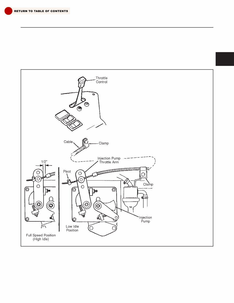
THROTTLE ADJUSTMENT
(See Figure 2C-1)
Located on the control panel to the right of the opera-
tors seat, the throttle control is used to regulate
engine speed. Adjust the throttle as shown in Figure
2C-1.
SECTION 2C. CONTROL ADJUSTMENTS
2C-1
2C
Figure 2C-1. Throttle Control Adjustment
STEP 1
Push throttle to high idle position.
Push injector pump throttle arm to
the high idle (speed position.
STEP 2
Slide outer cable housing in
clamp until housing is 1/2 inch
from injector pump throttle lever.
Tighten clamp.
STEP 3
Install wire stop against injector
pump throttle pivot and tighten.
STEP 4
Start engine and check low and
high idle speeds of engine. Low
idle should be 1330 RPM and
high is 3150 RPM. Make fine
adjustments using the injector
pump throttle arm stop screws.
You're Reading a Preview
What's Included?
Fast Download Speeds
Online & Offline Access
Access PDF Contents & Bookmarks
Full Search Facility
Print one or all pages of your manual
$33.99
$44.99
Viewed 53 Times Today


Secure transaction
What's Included?
Fast Download Speeds
Online & Offline Access
Access PDF Contents & Bookmarks
Full Search Facility
Print one or all pages of your manual
$33.99
$44.99
The Jacobsen LF-3400 & LF-3800 Repair Service Manual is a comprehensive guide covering the repair and maintenance of the LF-3400 2 Wheel Drive, LF-3800 2 Wheel Drive, LF-3400 4 Wheel Drive, LF-3800 4 Wheel Drive, and LF-3400 4 Wheel Drive Turbo Engine models.
- Language: English
- Pages: 273
- Format: PDF
- Platform: Windows and MAC
Professionals and DIY enthusiasts will find this manual invaluable as it includes detailed sections on controls, engine, drive train, brake system, steering, wheels & tires, hydraulics, chassis, electrical system, preventive maintenance, attachments, options, and miscellaneous information, along with specifications.


