Workshop manual Rider 15V2 Rider Pro 15 Rider Pro 18 English For Husqvarna Parts Call 606-678-9623 or 606-561-4983 www.mymowerparts.com
English – 1 Workshop manual Rider 15V2, Rider Pro 15 , Rider Pro 18 Contents Input axle .................................................. 42 Outgoing axles .......................................... 43 Replacing hydrostatic transmission wire ........ 44 Removal of hyrostatic transmission wire ... 44 Refitting hydrostatic transmission wire ...... 45 Bleeding the Hydrostatic and Hydraulic Systems ......................................................... 48 Adjustment of transmission neutral position .. 48 Transmission maintenance ............................ 50 Oil change ...................................................... 50 Removal of belt .............................................. 51 Checking and adjusting mower deck ground pressure ......................................................... 51 Checking and adjusting mower deck parallelism ...................................................... 52 Adjusting cutting height area .......................... 52 Adjusting cutting height .................................. 53 Replacing breakpin ........................................ 53 Removal of mowing deck ............................... 54 Return from Service Position ......................... 55 Removal of BioClip Plug ................................ 56 Replacing mowing deck belts ........................ 56 Belt replacement on BioClip 90 ................. 56 Belt replacement on Combi 103 ................ 57 Belt replacement on cutting unit with side or rear ejection and Combi 112, 122 ......... 58 Removal of blades with bearings ................... 59 Grinding and balancing of blades .................. 62 Pulse air valve intake filter ............................. 62 Cleaning the pulse air filter ....................... 62 Electrical system ............................................... 63 Circuit diagram 15V2 ..................................... 63 Circuit diagram Pro 15 ................................... 64 Circuit diagram Pro 18 ................................... 65 Replacing the light bulbs ................................ 66 Checking of safety system ............................. 67 Microswitch Cutting Unit ................................ 68 Microswitch: Neutral Position ......................... 68 Microswitch: Seat ........................................... 68 Hour meter ..................................................... 69 Main Fuse ...................................................... 69 Ignition and Starter Lock ................................ 69 Hydraulic System .............................................. 70 General .......................................................... 70 Hydraulic Hygiene ..................................... 70 Hydraulic Oils ............................................ 70 Fixing Oil Leaks ........................................ 70 Keeping Hydraulic Oil Clean ..................... 71 Working Methods ...................................... 71 System ........................................................... 71 Bleeding the Hydraulic System ................. 71 Power Steering ......................................... 71 Hydraulic oil filter, replacement ................. 71 Pressure Limiting Valve ............................ 72 Appendix: Trouble shooting schedule Safety regulations ............................................... 2 General instructions ......................................... 2 Special instructions .......................................... 2 Special tools ........................................................ 3 Technical data ..................................................... 4 Dimensions ...................................................... 4 Engine .............................................................. 4 Gear box .......................................................... 4 Electrical system .............................................. 4 Tightening moments ......................................... 4 Mowing deck .................................................... 5 Control points ................................................... 5 Play .................................................................. 5 Delivery and dealer service ................................ 6 Maintenance schedule ........................................ 8 Delivery measures ............................................ 10 To our dealer .................................................. 10 Packaging and unpacking .............................. 10 Parts enclosed in packaging .......................... 10 Battery ............................................................ 11 Steering wheel ............................................... 12 Tow plate ........................................................ 12 Oil levels ........................................................ 12 Wheels ........................................................... 13 Test running ................................................... 14 Speed regulator ............................................. 15 Administration ................................................ 15 Design and function .......................................... 16 General .......................................................... 16 Serial number ................................................. 16 Engine ............................................................ 17 Steering .......................................................... 18 Driving ............................................................ 19 Mowing deck .................................................. 20 Reparation instructions .................................... 23 Removing engine ........................................... 23 Replacing engine ........................................... 25 Fuel tank ........................................................ 28 Changing engine oil ....................................... 29 Checking and adjusting steering wires .......... 29 Replacing steering wires ................................ 30 Removal/installation of steering axle ............. 30 Removing/Fitting the Power Steering ............ 31 Removal/installation of wire wheel ................. 32 Checking and adjusting brake wire ................ 33 Checking and adjusting throttle control .......... 34 Checking and adjusting throttle wire .............. 35 Checking and adjusting choke wire ............... 35 Replacing articulated steering bearing ........... 36 Removal of swing axle ................................... 38 Replacing bushings ........................................ 39 Installation of swing axle ................................ 39 Removal/installation of hydrostatic transmission ................................................... 40 Replacing hydrostatic transmission axle sealing collars ................................................ 42 For Husqvarna Parts Call 606-678-9623 or 606-561-4983 www.mymowerparts.com
2 – English Safety regulations General instructions The workshop handbook is written for personnel who are assumed to have general ride-on mower repara- tion and service know-how. The workshop where the ride-on mower is repaired should be equipped with safety devices in accordance with local regulations. No-one should attempt to repair the ride-on mower without having first read and understood the contents of this handbook. The machine is tested and approved only with the equipment originally provided or recommended by the manufacturer. The below-mentioned boxes are included in this workshop handbook, as is appropriate. Special instructions The fuel used in the ride-on mower has the following hazardous characteristics: • Toxic fluid and fumes • Can cause eye and skin complaints • Can cause breathing difficulties • Highly flammable When using compressed air, do not direct the compressed air stream towards your, or anybody else's, body. Air can be forced into the blood stream, thereby constituting a danger to life. Use eye protection when working with tensioned springs. Use hearing protectors when test driving. After test driving, do not touch the silencer before it has cooled down. Risk of burn injuries. This especially applies if the ride-on mower is equipped with a catalytic converter. If consumed, the lining on and in the catalytic converter element is dangerous to health. Use protective gloves when working with the catalytic converter/silencer. The blades are sharp and can cause cutting injuries. Always use protective gloves when you are handling the blades. Use protective glasses when working with the mowing deck. If the belt's tension spring comes off and flies upwards, this can cause injury to persons. Use eye protection when working with the battery with the plugs removed. Be extra careful when handling battery acid. Spilling acid on the skin can cause severe burn injuries. If acid is spilt on the skin, rinse immediately with water. If acid gets into the eyes, this can cause blindness. Contact a doctor. Be careful with the maintenance of the battery. Explosive gas is formed in the battery. Never handle the battery when smoking or in the vicinity of naked flames or sparks. Otherwise, the battery can explode and cause severe injuries. IMPORTANT INFORMATION This box indicates a risk of damage to the material if the instructions are not followed. WARNING! The warning box indicates a risk of injury to persons if the instructions are not followed. IMPORTANT INFORMATION Waste oil and old filters should be handled as hazardous waste. For Husqvarna Parts Call 606-678-9623 or 606-561-4983 www.mymowerparts.com
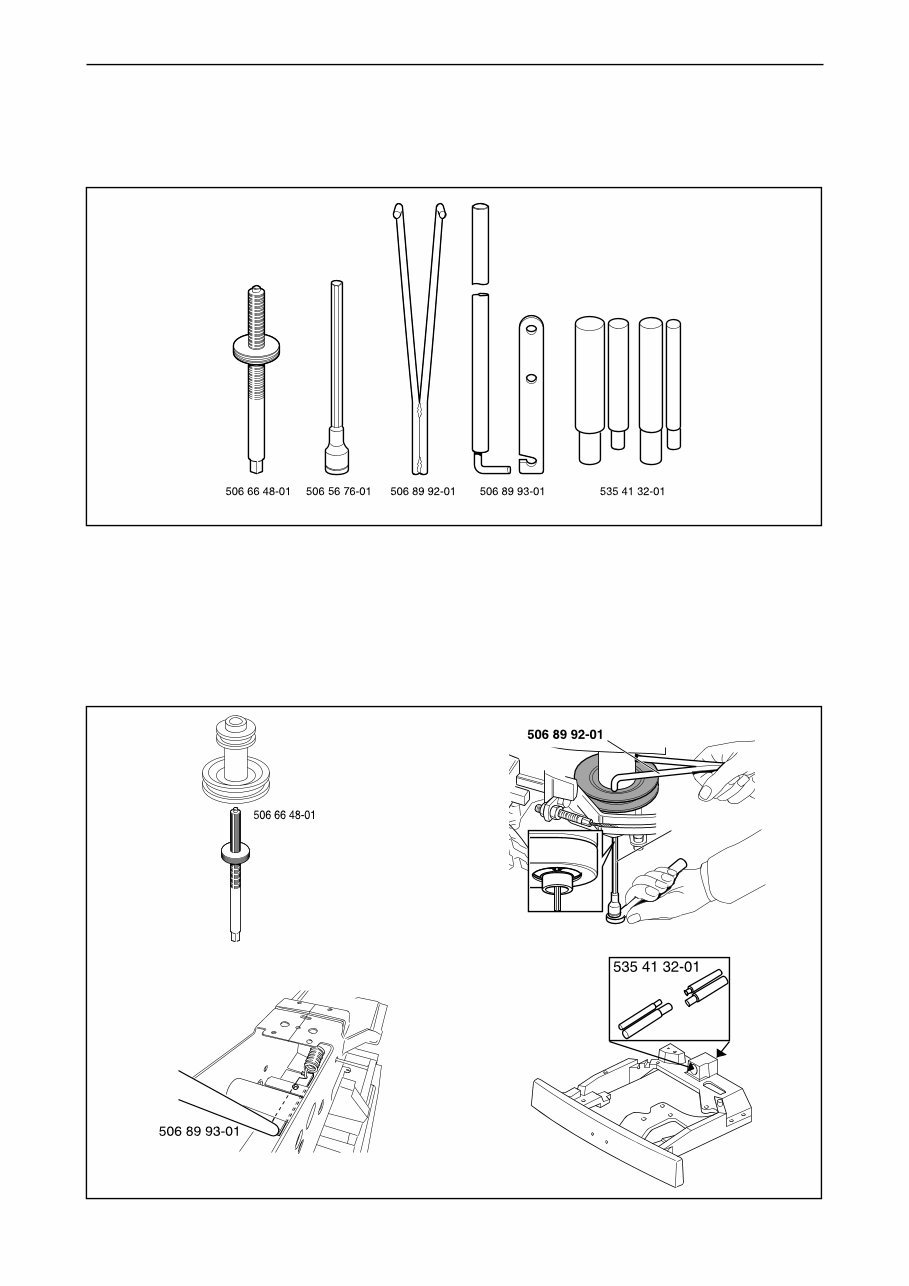
English – 3 506 56 76-01 Special tools The following special tools are used when working on the ride-on mower. Special tools for the engine and transmission are specified in the respective Workshop Manuals. 506 66 48-01 Puller for engine pulley. 506 56 76-01 Ball-ended Allen key 5/16" to unscrew the engine pulley socket head cap screw (Kawazaki). 506 89 92-01 Counter-hold for engine belt pulley. 506 89 93-01 Tool for the articulation spring. 535 41 32-01 Punch kit for pendulum shaft bushings. For Husqvarna Parts Call 606-678-9623 or 606-561-4983 www.mymowerparts.com
4 – English Dimensions: Rider Pro15V2 Rider Pro 15 Rider Pro 18 Length, base machine 2 000 mm/6,56 ft 2 030 mm/6,66 ft 2 030 mm/6,66 ft Width, base machine 900 mm/2,95 ft 900mm/2,95 ft 900 mm/2,95 ft Height 1 080 mm/3,54 ft 1 080 mm/3,54 ft 1 130 mm/3,71 ft Kerb weight, base machine 222 kg/488 lb 240 kg/528 lb 261 kg/574 lb Wheel base 860 mm/2,82 ft 873 mm/2,86 ft 873 mm/2,86 ft Track width, rear 625 mm/2,05 ft 625 mm/2,05 ft 625 mm/2,05 ft Track width, front 625 mm/2,05 ft 720 mm/2,36 ft 625 mm/2,05 ft Tyre size 16 x 6.50 x 8 16 x 6.50 x 8 16 x 6.50 x 8 Tyre pressure, front & rear 60 kPa/8,5 PSI 60 kPa/8,5 PSI 60 kPa/8,5 PSI Max. gradient 15° 15° 15° Engine: Manufacture Kawasaki Kawasaki Kawasaki V-Twin V-Twin V-Twin Modell FH430V-BS50 FH430V-BS50 FH531V-BS50 Power 11,2/15 kW/hp 11/15 kW/hp 13,2/18 kW/hp Displacement 431 cm 3 / 26,3 cu.in 431 cm 3 / 26,3 cu.in 494 cm 3 / 30,1 cu.in Fuel min 87 octane unleaded min 87 octane unleaded min 87 octane unleaded Tank volume 7 litres/7,4 US qt 7 litres/7,4 US qt 17 litres/18 US qt Oil SAE 30 or SAE 30 or SAE 30 or SAE 10W/30, 10W/40 SAE 10W/30, 10W/40 SAE 10W/30, 10W/40 class SF-SJ class SF-SJ class SF-SJ Oil volume excl. filter 1,5 litres / 1.6 US qt 1,5 litres / 1.6 US qt 1,5 litres / 1.6 US qt Oil volume incl. filter 1,7 litres / 1.8 US qt 1,7 litres / 1.8 US qt 1,7 litres / 1.8 US qt Start Electric start Electric start Electric start Gearbox: Manufacture Tuff Torq K 46 Tuff Torq K 62F Tuff Torq K 66M Oil SAE 10W/30 SAE 10W/30, SAE 10W/30, class SF-CC class SF-CC class SF-CC Oil capacity 2,2 litres/2,35 US qt 2,5 litres/2,64 US qt 2,5 litres/2,64 US qt Electrical system Type 12 V, negative earth 12 V, negative earth 12 V, negative earth Battery 12 V, 24 Ah 12 V, 24 Ah 12 V, 24 Ah Main fuse Flat pin yoke 15 A Flat pin yoke 15 A Flat pin yoke 15 A Spark plug Champion RCJ8Y, Champion RCJ8Y, Champion RCJ8Y, Electrode gap 0,75 mm / 0.030" 0,75 mm / 0.030" 0,75 mm / 0.030" Lights --- --- 2x12V 20 W Technical data Tightening moments Carrier steering 5-10 Nm 3,5-7 lbft Pulley steering wire 20-30 Nm 14-21 lbft Belt wheel 35-40 Nm 25-28 lbft Blades M10 bolt 45-50 Nm 32-36 lbft Blades M12 bolt 75-80 Nm 53-56 lbft Blade bearings 20-25 Nm 14-18 lbft Belt tensioner wheel 15-25 Nm 10-18 lbft Holder screws, engine 20-25 Nm 14-18 lbft Holder screws, gear box 20-25 Nm 14-18 lbft Engine pulley 70-80 Nm 50-56 lbft For Husqvarna Parts Call 606-678-9623 or 606-561-4983 www.mymowerparts.com
English – 5 Mowing deck BioClip 90 Combi 103 Combi 112 Cutting width 900 mm/35" 1 030 mm/41" 1 200 mm/44" Cutting heights 45-95 mm/1 9/16"-3 9/16" 45-95 mm/1 9/16"-3 9/16" 45-95 mm/1 9/16"-3 9/16" Blade length 440 mm/17,3" 410 mm/16,1" 420 mm/16,5" Sound level 100 dB(A) 100 dB(A) 100 dB(A) Width 1 000 mm/3,28 ft 1 115 mm/3,66 ft 1 230 mm/4,03 ft Weight 39 kg/85,8 lb 48 kg/105,5 lb 50 kg/110 lb Mowing deck Combi 122 Side ejector 97 Rear ejector 97 Cutting width 1 220 mm/48" 970 mm/38" 970 mm/38" Cutting heights 45-95 mm/1 9/16"-3 9/16" 40-90 mm/1 3/4"-3 3/4" 40-90 mm/1 3/4"-3 3/4" Blade length 450 mm/17,7" 350 mm/13,8" 350 mm/13,8" Sound level 100 dB(A) 100 dB(A) 100 dB(A) Width 1 330 mm/4,36 ft 1 300 mm/4,27 ft 1 075 mm/3,53 ft Weight 60 kg/132 lb 45 kg/99 lb 48 kg/105,5 lb Control points Mowing deck parallelism with cutting height in pos. 1: ± 2 mm ± 0,079" Inspection of cutting height (cover-ground) in position 1: Bio 90, 103 = 40 mm 1 7/16" Other = 35 mm 1, 3/8" Dist. between support plate and drive belt: 3–6 mm 1/8" - 1/4" Distance belt tensioner control lever and belt guide, disengaged unit: 17 ± 5 mm 7/16" ± 3/16" Play Brake wire: 1 mm 0,040" Wire for hydrostatic transmission pedals: 0 mm 0" Technical data For Husqvarna Parts Call 606-678-9623 or 606-561-4983 www.mymowerparts.com
6 – English Delivery and dealer service Pre-delivery service 1. Top up battery with acid and recharge for four hours. 2. Fit steering wheel, seat and any optional equipment. 3. Fit cutting unit. 4. Adjust cutting unit: Adjust lift springs (effective weight of cutting unit should be 12–15 kg (26,5-33 lb), or set to maximum lift if brush is to be fitted). Applies to BioClip and Combi. Adjust cutting unit so that rear edge is about 2–4 mm (1/8") higher than front edge. Adjust cutting unit height setting so that cutting height limit is 5 mm (3/16")above the frame of the unit at the lowest cutting height. 5. Check that the right amount of oil is in the transmission. 6. Check and adjust tyre pressure (60 kPa, 0,6 bar, 8,5 PSI). 7. Connect battery. 8. Fill with fuel and start engine. 9. Check that machine does not move in neutral. 10. Check: Forward drive. Reverse drive. Operation of blades. Seat safety switch. Lift lever safety switch. Safety switch for hydrostatic transmission pedals. 11. Check engine speed Rider 15 2,900 ±100 rpm, Rider 18 3,000 ±75 rpm. 12. Tell customer about: Need and benefits of following the service schedule. Need and benefits of having machine serviced every 300 hours. Service and the effect of the service journal on the machine’s second-hand value. Application areas for BioClip and Combi. 13. Complete proof of sale, etc. After first 8 hours 1. Change engine oil. For Husqvarna Parts Call 606-678-9623 or 606-561-4983 www.mymowerparts.com
English – 7 300 hour service 1. Inspect the machine. Agree with the customer as to what additional work is to be carried out. 2. Carry out 25 hour service. 3. Carry out 50 hour service. 4. Carry out 100 hour service. 5. Clean the combustion chamber and grind the valve seats. 6. Check the engine’s valve clearance. 7. Replace the air filter’s pre-filter (plastic foam). At least once a season 1. Clean the engine’s cooling air intake (25 hours). 2. Replace the air filter’s pre-filter (plastic foam) (300 hours). 3. Replace the air filter’s paper insert (200 hours). 4. Change the engine oil (100 hours). 5. Change the engine’s oil filter (200 hours). 6. Adjust the mowing height setting (50 hours). 7. Adjust the parking brake (50 hours). 8. Inspect the flame guard/spark arrester, optional equipment (50 hours). 9. Clean/replace the spark plug (100 hours). 10. Replace the fuel filter in the fuel line (100 hours). 11. Clean / replace the pulse air filter on Pro 15 and Pro 18 (100 hours). 12. Clean the cooling fins (100 hours). 13. Check the engine’s valve clearance (300 hours). 14. Change the oil in the transmission (500 hours). 15. Change the filter in the transmission, Pro 18 (500 hours). 16. 300 hours service is carried out by an authorised service workshop. 25 hour service 1. Check the fuel pump’s air filter. 2. Check/clean the engine cooling air intake. 3. Clean the cooling air intake to the transmission. 4. Clean the air filter’s pre-filter (plastic foam). 50 hour service 1. Carry out 25 hour service. 2. Clean/replace the air filter cartridge (paper filter). (More frequent intervals in dusty conditions.) 3. Check/adjust the mowing height setting. 4. Check/adjust the parking brake. 5. Inspect the flame guard/spark arrester. (optional equipment) 100 hour service 1. Carry out 25 hour service. 2. Carry out 50 hour service. 3. Change the engine oil. 4. Check whether the engine’s oil filter needs changing (every 200 hours). 5. Clean/replace the spark plug. 6. Replace the fuel filter in the fuel line. 7. Clean / replace the pulse air filter on Pro 15 and Pro 18. 8. Clean the cooling fins on the engine and trans- mission. 9. Check whether the oil and filter need changing in the transmission (every 500 hours). 10. Check whether the air filter’s paper insert needs cleaning or changing (every 200 hours). Delivery and dealer service For Husqvarna Parts Call 606-678-9623 or 606-561-4983 www.mymowerparts.com
8 – English Maintenance schedule The following is a list of the maintenance which should be conducted on the machine. Most of the points that are not covered by this workshop manual are covered by the operator’s manual. ● = Covered by this workshop manual. ❍ = Not covered by this workshop manual or operating Instructions. ▼ = Described in the operating Instructions. Delivery and dealer service Check for fuel and oil leakage - ❍ Check the parking brake 33 ● Check the engine oil level 12 ● Check the fuel pump air filter - ▼ Check the seat safety switch 67 ● Check the lift lever safety switch 67 ● Check the safety switch, pedal system 67 ● Check/clean the engine cooling air intake - ▼ Check the cutting unit: - ● • blades are secure 60 ● • condition of blades (sharpness, shape, etc.) 62 ● • blade synchronisation (90° between BioClip) 57 ● Check steering wires (for play, etc.) 29 ● Check fasteners (screws, nuts, etc.) - ❍ Start engine and blades, listen for noise - ❍ Clean underside of cutting unit - ▼ Clean transmission air intake - ▼ Check battery acid level 11 ● Check transmission oil level 13 ● Check condition of V-belts, pulleys, etc. - ❍ Check for damage - ❍ Check tyre pressures (60 kPa/9,5 PSI) 13 ● Check for damage to wire guide at articulated joint - ❍ Clean thoroughly around engine - ▼ Clean thoroughly around transmission - ▼ Clean all belts, pulleys, etc. - ▼ Lubricate belt tensioner (nipple) - ▼ Lubricate triangle link (nipple) - ▼ Lubricate joints and seat skid rails. - ▼ Lubricate all wires - ▼ Lubricate joints on cutting unit - ▼ Clean inside frame tunnel - ❍ Lubricate pedal mechanism inside frame tunnel - ▼ Lubricate the gear control - ▼ Lubricate the parking brake wire - ▼ Lubricate throttle control - ▼ Maintenance interval in hours Daily main- tenance before after Weekly 3) main- tenance At least once a year 25 50 100 300 Page Maintenance For Husqvarna Parts Call 606-678-9623 or 606-561-4983 www.mymowerparts.com
English – 9 Delivery and dealer service ● = Covered by this workshop manual. ❍ = Not covered by this workshop manual or operating Instructions. ▼ = Described in the operating Instructions. 1) First change after 8 hours. When driving with a heavy load or when the ambient temperature is high, replace every 50 hours. 2) Clean and replace the filter more often in dusty conditions. 3) For daily use of the machine lubrication should be conducted twice a week. 4) Conducted by authorised service workshop. 5) Pro 18 only. WARNING! No service procedures must be conducted on the engine or cutting unit unless: • The engine is switched off. • The ignition key is removed. • The ignition cables are removed from the plugs. • The parking brake is applied. • The cutting unit is disengaged. Lubricate choke control - ▼ Lubricate steering chain inside frame tunnel - ▼ Check steering wires inside frame tunnel 29 ● Clean engine cooling air intake - ▼ ▼ Clean the air filter’s pre-filter (plastic foam) - ▼ ▼ Change engine oil 1) 29 ● ● Clean the air filter’s cartridge 2) (paper filter) - ▼ ▼ Check/adjust cutting height setting 51 ● ● Check/adjust parking brake 33 ● ● Inspect flame guard/spark arrestor (optional equipment) - ❍ ❍ Change the engine’s oil filter (every 200 hours). - ▼ ▼ Replace the hydraulic oil filter (every 200 hours) 4-5) 71 ● ● Clean/replace spark plugs - ▼ ▼ Replace fuel filter in pipe - ▼ ▼ Clean / replace pulse air filter (Pro 15, Pro 18) 62 ● ● Clean the cooling fins - ❍ ❍ Check engine valve clearance 4) - ❍ ❍ Check whether oil change 4) or filter change 4-5) are necessary for gearbox (every 500 hrs) 50 ● ● Replace the air filter’s pre-filter (plastic foam) 2) - ▼ ▼ Replace the air filter (paper filter) 2) (every 200 hours) - ▼ ▼ Carry out 300 hour service 4) 7 ● ● Maintenance interval in hours Daily main- tenance before after Weekly 3) main- tenance At least once a year 25 50 100 300 Page Maintenance For Husqvarna Parts Call 606-678-9623 or 606-561-4983 www.mymowerparts.com
You're Reading a Preview
What's Included?
Lifetime Access
Fast Download Speeds
Online & Offline Access
Access PDF Contents & Bookmarks
Full Search Facility
Print one or all pages of your manual
$41.99$54.99
Husqvarna Rider 15V2, Rider Pro 15, Rider Pro 18 Mower Complete Workshop Service Repair Manual
Thank you for considering this comprehensive Workshop Service Repair Manual for the Husqvarna Rider 15V2, Rider Pro 15, and Rider Pro 18 Mower.
This manual is an invaluable resource for both professional mechanics and DIY enthusiasts, covering every service and repair procedure with easy-to-follow step-by-step instructions and detailed illustrations.
Upon obtaining this manual, you have the freedom to print specific pages, chapters, or the entire document. Additionally, you can conveniently access it on your tablet or smartphone.
All models, engines, trim, and transmission types are included in this high-quality manual, encompassing all repair procedures from A to Z.
Compatible with all PC and MAC computers, tablets, and mobile phones, this manual requires only Adobe Reader, which is commonly pre-installed or available for free download.
Upon payment confirmation via Visa, MasterCard, or PayPal, the manual will be promptly delivered to the email address provided during checkout.
Your satisfaction is guaranteed with this comprehensive Workshop Service Repair Manual.
Reviews
Q&A
Recently Viewed
5,521,897Happy Clients
2,594,462eManuals
1,120,453Trusted Sellers
15Years in Business
Price:
Actual Price:
Husqvarna Rider 15V2, Rider Pro 15, Rider Pro 18 Mower Complete Workshop Service Repair Manual











 Lifetime Access




