

Cub Cadet LTX Series Riding Tractor Service & Repair Manual
What's Included?
Fast Download Speeds
Online & Offline Access
Access PDF Contents & Bookmarks
Full Search Facility
Print one or all pages of your manual

LTX Series Riding Tractors
NOTE: These materials are for use by trained technicians who are experienced in the service and repair of outdoor power
equipment of the kind described in this publication, and are not intended for use by untrained or inexperienced individuals.
These materials are intended to provide supplemental information to assist the trained technician. Untrained or inexperi-
enced individuals should seek the assistance of an experienced and trained professional. Read, understand, and follow all
instructions and use common sense when working on power equipment. This includes the contents of the product’s Oper-
ators Manual, supplied with the equipment. No liability can be accepted for any inaccuracies or omission in this publication,
although care has been taken to make it as complete and accurate as possible at the time of publication. However, due to
the variety of outdoor power equipment and continuing product changes that occur over time, updates will be made to these
instructions from time to time. Therefore, it may be necessary to obtain the latest materials before servicing or repairing a
product. The company reserves the right to make changes at any time to this publication without prior notice and without
incurring an obligation to make such changes to previously published versions. Instructions, photographs and illustrations
used in this publication are for reference use only and may not depict actual model and component parts.
© Copyright 2012 MTD Products Inc. All Rights Reserved


I
Chapter 1: Introduction
Professional Shop Manual intent . . . . . . . . . . . . . . . . . . . . . . . . . . . . . . . . . . 1
Fasteners. . . . . . . . . . . . . . . . . . . . . . . . . . . . . . . . . . . . . . . . . . . . . . . . . . . . . 1
Assembly . . . . . . . . . . . . . . . . . . . . . . . . . . . . . . . . . . . . . . . . . . . . . . . . . . . . 3
Description of the 900 series . . . . . . . . . . . . . . . . . . . . . . . . . . . . . . . . . . . . . 3
Model and Serial Numbers . . . . . . . . . . . . . . . . . . . . . . . . . . . . . . . . . . . . . . . 4
Chapter 2: Engine related parts
Muffler . . . . . . . . . . . . . . . . . . . . . . . . . . . . . . . . . . . . . . . . . . . . . . . . . . . . . . . 5
Fuel tank removal/replacement . . . . . . . . . . . . . . . . . . . . . . . . . . . . . . . . . . . 8
Fuel Line . . . . . . . . . . . . . . . . . . . . . . . . . . . . . . . . . . . . . . . . . . . . . . . . . . . . . 9
Evaporative (EVAP) emissions system . . . . . . . . . . . . . . . . . . . . . . . . . . . . 10
Roll over valve vent . . . . . . . . . . . . . . . . . . . . . . . . . . . . . . . . . . . . . . . . . . . 12
Chapter 3: Steering
Steering alignment . . . . . . . . . . . . . . . . . . . . . . . . . . . . . . . . . . . . . . . . . . . . 15
Axles . . . . . . . . . . . . . . . . . . . . . . . . . . . . . . . . . . . . . . . . . . . . . . . . . . . . . . . 17
Sector gear and steering pinion gear . . . . . . . . . . . . . . . . . . . . . . . . . . . . . . 19
Steering shaft and hex bushing . . . . . . . . . . . . . . . . . . . . . . . . . . . . . . . . . . 21
Pivot bar . . . . . . . . . . . . . . . . . . . . . . . . . . . . . . . . . . . . . . . . . . . . . . . . . . . . 23
Chapter 6B: Electronic Power Steering
Rubber Torsion Coupling . . . . . . . . . . . . . . . . . . . . . . . . . . . . . . . . . . . . . . . 25
EPS Module . . . . . . . . . . . . . . . . . . . . . . . . . . . . . . . . . . . . . . . . . . . . . . . . . 25
EPS motor & gearbox . . . . . . . . . . . . . . . . . . . . . . . . . . . . . . . . . . . . . . . . . . 26
Troubleshooting the EPS (without the 725-05419 EPS tester) . . . . . . . . . . 27
EPS removal/replacement . . . . . . . . . . . . . . . . . . . . . . . . . . . . . . . . . . . . . . 33
Chapter 4: Body panels
What is covered by this chapter . . . . . . . . . . . . . . . . . . . . . . . . . . . . . . . . . . 35
Hood . . . . . . . . . . . . . . . . . . . . . . . . . . . . . . . . . . . . . . . . . . . . . . . . . . . . . . . 36
Hood components: Headlight removal . . . . . . . . . . . . . . . . . . . . . . . . . . . . . 37
Hood components: side vent removal . . . . . . . . . . . . . . . . . . . . . . . . . . . . . 38
Hood components: grill removal . . . . . . . . . . . . . . . . . . . . . . . . . . . . . . . . . . 39
Hood components: pivot bracket removal . . . . . . . . . . . . . . . . . . . . . . . . . . 40
Seat and Fenders . . . . . . . . . . . . . . . . . . . . . . . . . . . . . . . . . . . . . . . . . . . . . 41
Dash Panel . . . . . . . . . . . . . . . . . . . . . . . . . . . . . . . . . . . . . . . . . . . . . . . . . . 50
Table of Contents

II
Chapter 5: Hydro. Drive and brake system
About this chapter . . . . . . . . . . . . . . . . . . . . . . . . . . . . . . . . . . . . . . . . . . . . . 55
Externally repairable drive system problems . . . . . . . . . . . . . . . . . . . . . . . . 56
Indications that a transaxle is not warrantable . . . . . . . . . . . . . . . . . . . . . . . 61
Brake adjustment . . . . . . . . . . . . . . . . . . . . . . . . . . . . . . . . . . . . . . . . . . . . . 62
Neutral control adjustment . . . . . . . . . . . . . . . . . . . . . . . . . . . . . . . . . . . . . . 64
Linkage: pedal shaft . . . . . . . . . . . . . . . . . . . . . . . . . . . . . . . . . . . . . . . . . . . 66
Pedal shaft assembly removal . . . . . . . . . . . . . . . . . . . . . . . . . . . . . . . . . . . 67
Belt control; tensioner and idler pulleys . . . . . . . . . . . . . . . . . . . . . . . . . . . . 72
Drive belt replacement . . . . . . . . . . . . . . . . . . . . . . . . . . . . . . . . . . . . . . . . . 75
Changing transaxle hydraulic fluid . . . . . . . . . . . . . . . . . . . . . . . . . . . . . . . . 81
Brakes . . . . . . . . . . . . . . . . . . . . . . . . . . . . . . . . . . . . . . . . . . . . . . . . . . . . . 83
Transaxle removal and replacement . . . . . . . . . . . . . . . . . . . . . . . . . . . . . . 85
Chapter 6: CVT Drive and brake system
About this chapter . . . . . . . . . . . . . . . . . . . . . . . . . . . . . . . . . . . . . . . . . . . . . 93
About the variable speed drive system. . . . . . . . . . . . . . . . . . . . . . . . . . . . . 93
Externally repairable drive system problems: . . . . . . . . . . . . . . . . . . . . . . . . 94
Indications that a transaxle is not warrantable . . . . . . . . . . . . . . . . . . . . . . . 97
Brake adjustment . . . . . . . . . . . . . . . . . . . . . . . . . . . . . . . . . . . . . . . . . . . . . 97
Gear selector . . . . . . . . . . . . . . . . . . . . . . . . . . . . . . . . . . . . . . . . . . . . . . . . 99
Tensioner pulley control rod . . . . . . . . . . . . . . . . . . . . . . . . . . . . . . . . . . . . 100
Linkage: pedal shaft . . . . . . . . . . . . . . . . . . . . . . . . . . . . . . . . . . . . . . . . . . 102
Pedal shaft assembly removal: . . . . . . . . . . . . . . . . . . . . . . . . . . . . . . . . . . 102
Linkage: pedal tie strap . . . . . . . . . . . . . . . . . . . . . . . . . . . . . . . . . . . . . . . 107
Belt control: tension make-up pulley . . . . . . . . . . . . . . . . . . . . . . . . . . . . . . 109
Belt control: variable speed pulley . . . . . . . . . . . . . . . . . . . . . . . . . . . . . . . 111
Belt control: tensioner pulleys . . . . . . . . . . . . . . . . . . . . . . . . . . . . . . . . . . . 114
Drive belt replacement . . . . . . . . . . . . . . . . . . . . . . . . . . . . . . . . . . . . . . . . 118
Transaxle removal and replacement . . . . . . . . . . . . . . . . . . . . . . . . . . . . . 124
Transaxle repair . . . . . . . . . . . . . . . . . . . . . . . . . . . . . . . . . . . . . . . . . . . . . 129
Chapter 7: electrical system
Introduction . . . . . . . . . . . . . . . . . . . . . . . . . . . . . . . . . . . . . . . . . . . . . . . . . 141
RMC Module . . . . . . . . . . . . . . . . . . . . . . . . . . . . . . . . . . . . . . . . . . . . . . . . 141
Key switch . . . . . . . . . . . . . . . . . . . . . . . . . . . . . . . . . . . . . . . . . . . . . . . . . 142
RMC Module . . . . . . . . . . . . . . . . . . . . . . . . . . . . . . . . . . . . . . . . . . . . . . . . 144
RMC module plug test (electric PTO) . . . . . . . . . . . . . . . . . . . . . . . . . . . . . 145
RMC module plug test (manual PTO) . . . . . . . . . . . . . . . . . . . . . . . . . . . . 147
Electric PTO switch . . . . . . . . . . . . . . . . . . . . . . . . . . . . . . . . . . . . . . . . . . 149
PTO relay . . . . . . . . . . . . . . . . . . . . . . . . . . . . . . . . . . . . . . . . . . . . . . . . . . 150
PTO switch (manual PTO) . . . . . . . . . . . . . . . . . . . . . . . . . . . . . . . . . . . . . 151
Brake switch (manual PTO) . . . . . . . . . . . . . . . . . . . . . . . . . . . . . . . . . . . . 152
Brake switch (electric PTO) . . . . . . . . . . . . . . . . . . . . . . . . . . . . . . . . . . . . 153
Park brake switch . . . . . . . . . . . . . . . . . . . . . . . . . . . . . . . . . . . . . . . . . . . . 153
Reverse Safety Switch . . . . . . . . . . . . . . . . . . . . . . . . . . . . . . . . . . . . . . . . 154
Seat Safety Switch . . . . . . . . . . . . . . . . . . . . . . . . . . . . . . . . . . . . . . . . . . . 155
Starter solenoid . . . . . . . . . . . . . . . . . . . . . . . . . . . . . . . . . . . . . . . . . . . . . 156

III
Start Circuit . . . . . . . . . . . . . . . . . . . . . . . . . . . . . . . . . . . . . . . . . . . . . . . . . 157
Run Circuit . . . . . . . . . . . . . . . . . . . . . . . . . . . . . . . . . . . . . . . . . . . . . . . . . 160
Run Circuit / Reverse Caution mode . . . . . . . . . . . . . . . . . . . . . . . . . . . . . 161
Engine shutdown circuits . . . . . . . . . . . . . . . . . . . . . . . . . . . . . . . . . . . . . . 162
Charging circuit . . . . . . . . . . . . . . . . . . . . . . . . . . . . . . . . . . . . . . . . . . . . . . 163
PTO Circuit (electric PTO) . . . . . . . . . . . . . . . . . . . . . . . . . . . . . . . . . . . . . 168
Reverse Mower Control (RMC) circuit operation . . . . . . . . . . . . . . . . . . . . 170
Electrical diagnosis . . . . . . . . . . . . . . . . . . . . . . . . . . . . . . . . . . . . . . . . . . . 172
Electronics . . . . . . . . . . . . . . . . . . . . . . . . . . . . . . . . . . . . . . . . . . . . . . . . . 172
Electrical environment: AC Vs. DC . . . . . . . . . . . . . . . . . . . . . . . . . . . . . . . 173
Ohm’s Law . . . . . . . . . . . . . . . . . . . . . . . . . . . . . . . . . . . . . . . . . . . . . . . . . 174
Kirchhoff’s Current Law . . . . . . . . . . . . . . . . . . . . . . . . . . . . . . . . . . . . . . . 174
Kirchhoff’s Voltage Law . . . . . . . . . . . . . . . . . . . . . . . . . . . . . . . . . . . . . . . 175
How the system is wired together . . . . . . . . . . . . . . . . . . . . . . . . . . . . . . . . 175
Types of circuits . . . . . . . . . . . . . . . . . . . . . . . . . . . . . . . . . . . . . . . . . . . . . 176
Series . . . . . . . . . . . . . . . . . . . . . . . . . . . . . . . . . . . . . . . . . . . . . . . . . . . . . 176
Parallel . . . . . . . . . . . . . . . . . . . . . . . . . . . . . . . . . . . . . . . . . . . . . . . . . . . . 176
Series/parallel . . . . . . . . . . . . . . . . . . . . . . . . . . . . . . . . . . . . . . . . . . . . . . . 177
Shorts . . . . . . . . . . . . . . . . . . . . . . . . . . . . . . . . . . . . . . . . . . . . . . . . . . . . . 177
Opens . . . . . . . . . . . . . . . . . . . . . . . . . . . . . . . . . . . . . . . . . . . . . . . . . . . . . 177
Increased resistance . . . . . . . . . . . . . . . . . . . . . . . . . . . . . . . . . . . . . . . . . 177
The Tools . . . . . . . . . . . . . . . . . . . . . . . . . . . . . . . . . . . . . . . . . . . . . . . . . . 178
Digital multimeter . . . . . . . . . . . . . . . . . . . . . . . . . . . . . . . . . . . . . . . . . . . . 179
Wiring diagram or schematic . . . . . . . . . . . . . . . . . . . . . . . . . . . . . . . . . . . 180
Fused jumper wires . . . . . . . . . . . . . . . . . . . . . . . . . . . . . . . . . . . . . . . . . . 180
Test lights . . . . . . . . . . . . . . . . . . . . . . . . . . . . . . . . . . . . . . . . . . . . . . . . . . 180
Self-powered continuity lights . . . . . . . . . . . . . . . . . . . . . . . . . . . . . . . . . . . 180
Ammeters and specialized charging system testers . . . . . . . . . . . . . . . . . 181
Batteries . . . . . . . . . . . . . . . . . . . . . . . . . . . . . . . . . . . . . . . . . . . . . . . . . . . 182
Charging the battery . . . . . . . . . . . . . . . . . . . . . . . . . . . . . . . . . . . . . . . . . . 182
Checking battery condition . . . . . . . . . . . . . . . . . . . . . . . . . . . . . . . . . . . . . 183
Battery Testers . . . . . . . . . . . . . . . . . . . . . . . . . . . . . . . . . . . . . . . . . . . . . . 184
Adjustable load testers . . . . . . . . . . . . . . . . . . . . . . . . . . . . . . . . . . . . . . . . 184
Fixed load testers . . . . . . . . . . . . . . . . . . . . . . . . . . . . . . . . . . . . . . . . . . . . 185
Conductance testers . . . . . . . . . . . . . . . . . . . . . . . . . . . . . . . . . . . . . . . . . . 185
Battery discharge test . . . . . . . . . . . . . . . . . . . . . . . . . . . . . . . . . . . . . . . . . 186
Storage of batteries . . . . . . . . . . . . . . . . . . . . . . . . . . . . . . . . . . . . . . . . . . 186
Electrical Troubleshooting . . . . . . . . . . . . . . . . . . . . . . . . . . . . . . . . . . . . . 187
Voltage Drop Test . . . . . . . . . . . . . . . . . . . . . . . . . . . . . . . . . . . . . . . . . . . . 189
Testing switches . . . . . . . . . . . . . . . . . . . . . . . . . . . . . . . . . . . . . . . . . . . . . 192
Diodes . . . . . . . . . . . . . . . . . . . . . . . . . . . . . . . . . . . . . . . . . . . . . . . . . . . . 193
Relay . . . . . . . . . . . . . . . . . . . . . . . . . . . . . . . . . . . . . . . . . . . . . . . . . . . . . 195
Schematics . . . . . . . . . . . . . . . . . . . . . . . . . . . . . . . . . . . . . . . . . . . . . . . . . 196

IV
Chapter 8: Cutting Decks and lift shaft
Cutting decks . . . . . . . . . . . . . . . . . . . . . . . . . . . . . . . . . . . . . . . . . . . . . . . 201
Deck removal . . . . . . . . . . . . . . . . . . . . . . . . . . . . . . . . . . . . . . . . . . . . . . . 201
Cleaning the deck . . . . . . . . . . . . . . . . . . . . . . . . . . . . . . . . . . . . . . . . . . . . 204
To clean the deck while it is removed: . . . . . . . . . . . . . . . . . . . . . . . . . . . . . 204
Blades . . . . . . . . . . . . . . . . . . . . . . . . . . . . . . . . . . . . . . . . . . . . . . . . . . . . . 205
Spindles . . . . . . . . . . . . . . . . . . . . . . . . . . . . . . . . . . . . . . . . . . . . . . . . . . . 207
PTO belt . . . . . . . . . . . . . . . . . . . . . . . . . . . . . . . . . . . . . . . . . . . . . . . . . . . 209
Timing belt . . . . . . . . . . . . . . . . . . . . . . . . . . . . . . . . . . . . . . . . . . . . . . . . . 213
Leveling the deck . . . . . . . . . . . . . . . . . . . . . . . . . . . . . . . . . . . . . . . . . . . . 215
Side to Side Leveling . . . . . . . . . . . . . . . . . . . . . . . . . . . . . . . . . . . . . . . . . 215
Front To Rear Leveling . . . . . . . . . . . . . . . . . . . . . . . . . . . . . . . . . . . . . . . . 216
Deck Wheel Adjustment . . . . . . . . . . . . . . . . . . . . . . . . . . . . . . . . . . . . . . . 217
Deck lift shaft assembly bushings . . . . . . . . . . . . . . . . . . . . . . . . . . . . . . . 217
Deck lift shaft assembly removal/replacement . . . . . . . . . . . . . . . . . . . . . . 218
Deck lift links and cables . . . . . . . . . . . . . . . . . . . . . . . . . . . . . . . . . . . . . . 220
Lubrication . . . . . . . . . . . . . . . . . . . . . . . . . . . . . . . . . . . . . . . . . . . . . . . . . 223
Engine maintenance . . . . . . . . . . . . . . . . . . . . . . . . . . . . . . . . . . . . . . . . . . 223
Chapter 9: Maintenance intervals . . . . . . . . . . . . . . . . . . . . . . . . . . . . . . . . 223
The spark plug(s) . . . . . . . . . . . . . . . . . . . . . . . . . . . . . . . . . . . . . . . . . . . . 224
Air filter and foam pre-cleaner . . . . . . . . . . . . . . . . . . . . . . . . . . . . . . . . . . 225
Oil change . . . . . . . . . . . . . . . . . . . . . . . . . . . . . . . . . . . . . . . . . . . . . . . . . 226
Fuel system . . . . . . . . . . . . . . . . . . . . . . . . . . . . . . . . . . . . . . . . . . . . . . . . 227
Servicing the fuel system . . . . . . . . . . . . . . . . . . . . . . . . . . . . . . . . . . . . . . 227
Fuel filter . . . . . . . . . . . . . . . . . . . . . . . . . . . . . . . . . . . . . . . . . . . . . . . . . . . 227
Clean the engine . . . . . . . . . . . . . . . . . . . . . . . . . . . . . . . . . . . . . . . . . . . . 228
Lubricate the pedal shaft . . . . . . . . . . . . . . . . . . . . . . . . . . . . . . . . . . . . . . 228
Hydro-gear Appendix

Introduction
1
Professional Shop Manual intent
This Manual is intended to provide service dealers with an introduction to the mechanical aspects of the LTX
series of tractors.
• Detailed service information about the engine will be provided by the engine manufacturer, in most cases.
Disclaimer: The information contained in this manual is correct at the time of writing. Both the product and the infor-
mation about the product are subject to change without notice.
About the text format:
NOTE: is used to point out information that is relevant to the procedure, but does not fit as a step in the proce-
dure.
• Bullet points: indicate sub-steps or points.
Disclaimer: This manual is intended for use by trained, professional technicians.
• Common sense in operation and safety is assumed.
• In no event shall MTD or Cub Cadet be liable for poor text interpretation or poor execution of the proce-
dures described in the text.
• If the person using this manual is uncomfortable with any procedures they encounter, they should seek
the help of a qualified technician or Cub Cadet Technical Support.
Fasteners
• Most of the fasteners used on these mowers are sized in fractional inches. The engine and transmissions
are metric. For this reason, wrench sizes are frequently identified in the text, and measurements are given
in U.S. and metric scales.
• If a fastener has a locking feature that has worn, replace the fastener or apply a small amount of releas-
able thread locking compound such as Loctite® 242 (blue).
• Some fasteners like cotter pins are single-use items that are not to be reused. Other fasteners such as
lock washers, retaining rings, and internal cotter pins (hairpin clips) may be reused if they do not show
signs of wear or damage. This manual leaves that decision to the judgement of the technician.
Caution is used to point out potential danger to the technician, operator, bystanders, or sur-
rounding property. ! CAUTION
Warning indicates a potentially hazardous situation that, if not avoided, could result in death
of serious injury. ! WARNING ! DANGER
Danger indicates an imminently hazardous situation that, if not avoided, will result in death or
serious injury. This signal word is to be limited to the most extreme situations.
CHAPTER 1: INTRODUCTION
LTX Tractors
2
• Be prepared in case of emergency:
Keep a fire extinguisher nearby
Keep a first aid kit nearby
Keep emergency contact numbers handy
• Replace any missing or damaged safety labels on shop equipment.
• Replace any missing or damaged safety labels on equipment being serviced. ! CAUTION
• Grooming and attire:
Do not wear loose fitting clothing that may become entangled in equipment.
Long hair should be secured to prevent entanglement in equipment.
Jewelry is best removed.
• Protective gear: includes, but is not limited to
Clear eye protection ................................ while working around any machinery
Protective gloves ..................................... where necessary
Armored footwear .................................... when working around any machinery
Hearing protection ................................... in noisy environments
Chemically resistant gloves ..................... when working with chemicals or solvents
Respirator ................................................ when working with chemical or solvents
Appropriate tinted eye protection............. when cutting or welding
Flame resistant headgear, jacket, chaps . when cutting or welding ! WARNING ! CAUTION
• Remember that some hazards have a cumulative effect. A single exposure may
cause little or no harm, but continual or repeated exposure may cause very serious
harm.
• Clean spills and fix obviously dangerous conditions as soon as they are noticed.
• Lift and support heavy objects safely and securely.
• Be aware of your surroundings and potential hazards that are inherent to all power
equipment. All the labels in the world cannot protect a technician from an instant of
carelessness.
• Exhaust fumes from running engines contain carbon monoxide (CO). Carbon
monoxide is a colorless odorless gas that is fatal if inhaled in sufficient quantity.
Only run engines in well ventilated areas. If running engines indoors, use an
exhaust evacuation system with adequate make-up air ventilated into the shop. ! DANGER
Introduction
3
Assembly
Torque specifications may be noted in the part of the text that covers assembly, they may also be summarized in
tables along with special instructions regarding locking or lubrication. Whichever method is more appropriate will be
used. In many cases, both will be used so that the manual is handy as a quick-reference guide as well as a step-by-
step procedure guide that does not require the user to hunt for information.
The level of assembly instructions provided will be determined by the complexity of disassembly/reassembly,
and by the potential for unsafe conditions to arise from mistakes made in assembly.
Some instructions may refer to other parts of the manual for subsidiary procedures. This avoids repeating the
same procedure two or three times in the manual.
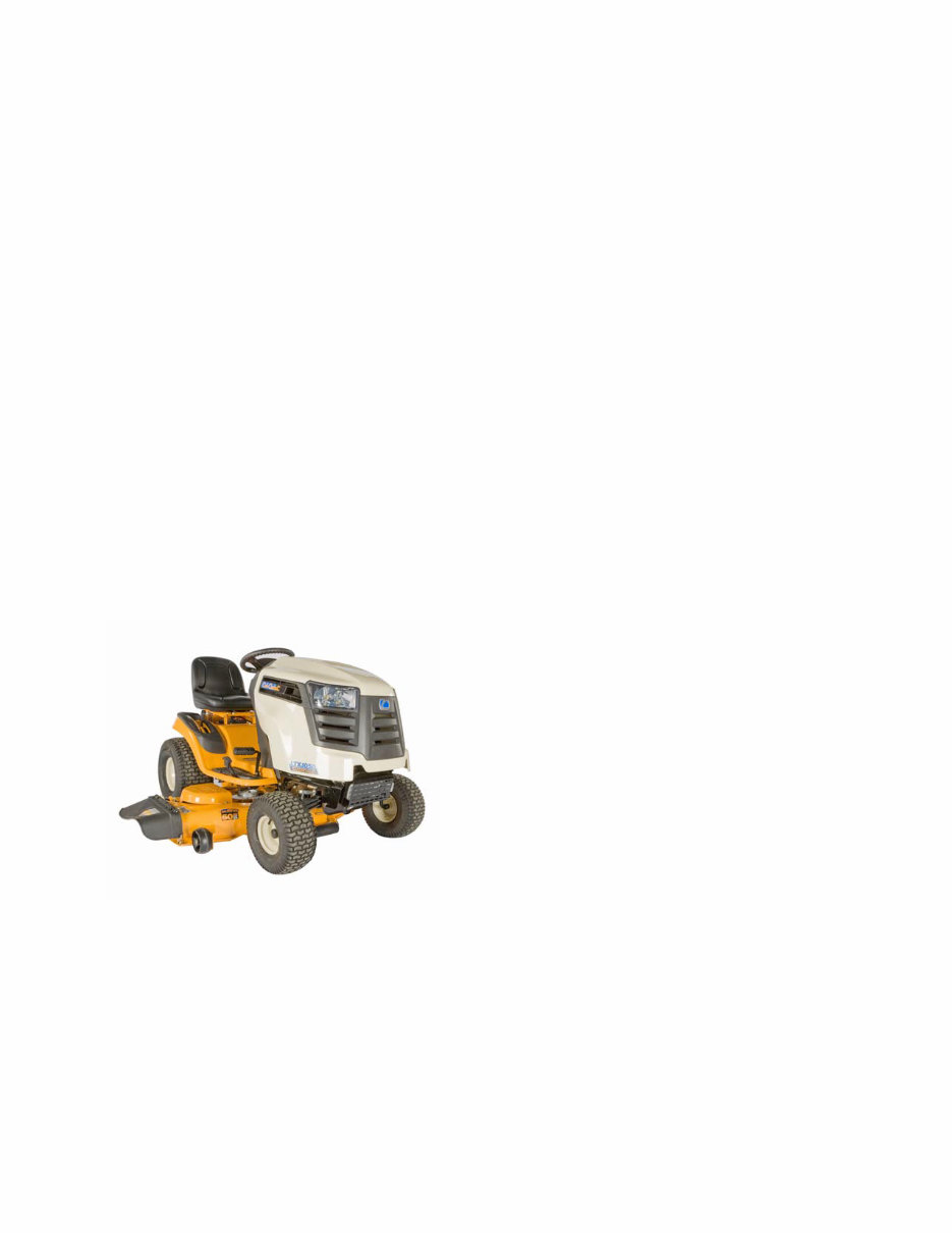
Description of the 900 series
The 900 series is a new tractor platform introduced in the 2009 season. This platform replaces the traditional 600
series tractor. See Figure 1.1.
New for the 900 series is:
• New stronger frame
• New hood and grill designs
• A new 42” timed deck
• A new 2 blade 46” deck
• Tighter turning radius
Figure 1.1

LTX Tractors
4
Model and Serial Numbers
The model and serial number tag can be found under
the seat. See Figure 1.2.
The serial number is located to the right of the model
number as shown above. See Figure 1.2.
The model number is 13AX90AR010 The break down of what the character mean is as follows:
1 .............................................................................................. Cuts grass
....3 .......................................................................................... Lawn tractor
.......A....................................................................................... Sales level/type of create
...........X................................................................................... Engine code
.............9. ................................................................................ Frame
.................0 ............................................................................. Drive system
....................A .......................................................................... Hood style
.........................R..................................................................... Deck (S = 42”, T = 46”, P=50”, R=42” timed deck)
.............................056 ............................................................. Customer number
The serial number is 1J078H30003. The serial number reads as follows:
1 .............................................................................................. Engineering level
..J............................................................................................. Month of production (J = October)
.....07 ....................................................................................... Day of the month
.........8 ..................................................................................... Last digit of the year
...........H................................................................................... Plant it was built in (Martin, TN)
..............3 ................................................................................ Assembly line number
.................0003 ....................................................................... Build number of unit
Figure 1.2
Model number Serial number
You're Reading a Preview
What's Included?
Fast Download Speeds
Online & Offline Access
Access PDF Contents & Bookmarks
Full Search Facility
Print one or all pages of your manual
$32.99
Viewed 94 Times Today


Secure transaction
What's Included?
Fast Download Speeds
Online & Offline Access
Access PDF Contents & Bookmarks
Full Search Facility
Print one or all pages of your manual
$32.99
This is a detailed service repair manual for the Cub Cadet LTX Series Rider, offering comprehensive guidance for both professional mechanics and DIY enthusiasts. It includes step-by-step instructions and detailed illustrations for all service and repair procedures.
The manual is available in digital format as a .PDF file, compatible with PC-based Windows operating systems and Mac. It is also printable for easy reference.
Key Features:
- Complete disassembly guidance with hundreds of photos and illustrations.
- Instant access to the manual saves on postage and packaging costs.
- Provides in-depth knowledge about your Cub Cadet LTX Series Rider.
- All pages are printable for convenience.
Don't miss out on the opportunity to enhance your understanding of your vehicle and effectively maintain its optimal performance. Purchase this manual now to gain valuable insights into your Cub Cadet LTX Series Rider.


