1 1. INTRODUCTION ........................................................................................................................ 1 2. NEW HOOD DESIGN ................................................................................................................. 3 3. HOOD PANEL REMOVAL: 1500 SERIES ................................................................................ 5 4. HOOD AND HINGE REMOVAL: 1500 SERIES ........................................................................ 6 5. REAR FENDER REMOVAL ....................................................................................................... 7 6. FUEL SYSTEM ........................................................................................................................... 9 7. FUEL SHUT-OFF SOLENOID ................................................................................................. 11 8. FUEL RELATED NO-START ISSUES ..................................................................................... 11 9. MUFFLER REMOVAL .............................................................................................................. 12 10. CUTTING DECK REMOVAL .................................................................................................... 13 11. DECK LIFT SHAFT ASSEMBLY ............................................................................................. 15 12. LIFT SHAFT BUSHINGS ......................................................................................................... 16 13. DECK LIFT CABLES AND PULLEYS ..................................................................................... 17 14. LEVELING THE CUTTING DECK ........................................................................................... 18 15. DASH PANEL REMOVAL ....................................................................................................... 20 16. CRUISE CONTROL AND PARK BRAKE LINKAGES ............................................................ 22 17. TRACTION DRIVE BELT REPLACEMENT: CVT ................................................................... 24 18. DRIVE SYSTEM ADJUSTMENT: CVT .................................................................................... 27 19. BRAKE ADJUSTMENT: CVT .................................................................................................. 30 20. SERVICING THE BRAKE PEDAL SHAFT BUSHINGS: ......................................................... 32 21. TRANSAXLE REPLACEMENT: CVT ...................................................................................... 34 22. TRANSAXLE SERVICE AND INTERNALS: CVT ................................................................... 36 23. TRACTION DRIVE BELT REPLACEMENT: HYDROSTATIC LT ........................................... 36 24. DRIVE SYSTEM ADJUSTMENT: HYDROSTATIC LT ........................................................... 39 25. HYDRO CONTROL ROD ADJUSTMENT ............................................................................... 42 26. BRAKES AND BRAKE ADJUSTMENT: HYDROSTATIC LT ................................................. 43 27. PEDAL BUSHING REPLACEMENT ........................................................................................ 46 28. TRANSAXLE SERVICE AND MAINTENANCE: HYDROSTATIC LT ...................................... 47 29. TRANSAXLE REPLACEMENT: HYDROSTATIC LT .............................................................. 49 30. TRACTION DRIVE BELT REPLACEMENT: HYDROSTATIC GT ........................................... 52 31. DRIVE SYSTEM ADJUSTMENT: HYDROSTATIC GT............................................................ 54 32. BRAKES AND BRAKE ADJUSTMENT: HYDROSTATIC GT ................................................. 58 33. TRANSAXLE SERVICE AND MAINTENANCE: HYDROSTATIC GT ..................................... 62 34. TRANSAXLE REPLACEMENT: HYDROSTATIC GT .............................................................. 64 35. STEERING GEAR AND STEERING PINION GEAR REPLACEMENT ................................... 67 36. STEERING ADJUSTMENT / ALIGNMENT ............................................................................. 68 37. PIVOT BAR SERVICE ............................................................................................................. 69 38. ELECTRICAL SYSTEM ........................................................................................................... 71 39. UNDERSTANDING THE PTO SWITCH ................................................................................... 77 Table of Contents
2
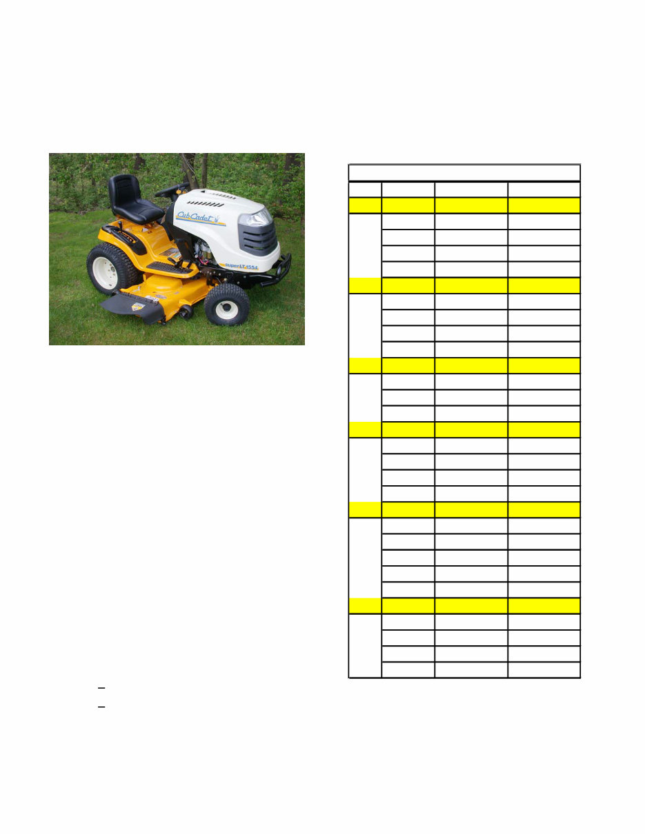
Series 1000 and 1500 1 1. INTRODUCTION Disclaimer: This service manual is intended to be used by trained technicians. Disclaimer: The information contained in this manual is current and accurate at the time of writing, but is sub- ject to change without notice. 1.1. Intent: This manual is intended to: • Provide specific service and repair procedures for a range of Cub Cadet 1000 and 1500 Series tractors manufactured for the 2005/2006 sea- son. • Highlight significant changes to the Cub Cadet 1000 Series since it’s introduction. 1.2. Engines: A variety of single cylinder and V-twin engines have been used in the 1000 series trac- tors. Kohler Courage line of single-cylinder and V-Twin engines is presently the most heavily used power source in the 1000 Series line 1.3. For specific engine service information, refer to the engine manufacturer’s service publications. 1.4. The engine is partially identified by the 4th digit of the factory number: • 13AX 11CG756 - Kohler Courage single cylinder • 13AP 11CP756 - Kohler courage V-Twin 1.5. Refer to the table provided for engine applica- tions in the 1000 series range. See Figure 1.5. Year Model # Factory # Engine 2001 1027 13A-328-101 9.0 HP BS 1170 13CD608G101 17.5 HP BS 1180 13AT608H101 18 HP BS 1212 14AJ808H101 21 HP BS 2002 1027 13A-328-101 9.0 HP BS 1170 13CD608G101 17.5 HP BS 1515 13A-201F100 15 HP KOH 1517 13A-231G100 17 HP KOH 2003 1525 13A-221F100 15 HP KAW 1527 13A-241G100 17 HP KAW 1529 13A-261H100 19 HP KAW 2004 LT 1018 13AL11CG710 18.5 HP BS LT 1022 13AB11CH710 22 HP BS LT 1024 13AR11CP710 24 HP BS GT 1222 14AB13CH710 22 HP BS 2005 LT 1042 13BX11CG710 19 HP KOH LT 1045 13AX11CH710 20 HP KOH LT 1046 13AP11CH710 23 HP KOH LT 1050 13AQ11CP71 0 26 HP KOH SLT 1554 13AK11CK710 27 HP KOH 2006 LT 1042 13AX11CG756 19 HP HOH LT 1045 13AX11CH756 20 HP KOH LT 1050 13AP11CP756 23 HP KOH SLT 1550 13AQ11BP756 25 HP KOH GT 1554 14AK13BK756 27 HP KOH 1000 Series Engine Applications Figure 1.5 Series 1000 and 1500
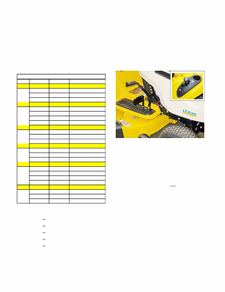
Series 1000 and 1500 2 1.6. Decks: Cutting decks ranging in width from 38” to 54” have been used on the 1000 Series plat- form. 1.7. There have been multiple versions of some decks, most particularly the 42”. Check the serial number when researching for parts or service information. 1.8. The deck size is identified by the 8th digit of the factory number: See Figure 1.8. • 13AX11CG 756 - 42” 2-blade deck • 13AX11CH 756 - 46” 3-blade deck • 13AP11CP 756 - 50” 3-blade deck • 13AQ11BP 756 - 50” 3-blade deck • 14AK13BK 756 - 54” 3-blade deck 1.9. Drive Systems: A variety of hydrostatic and CVT drive systems have been used on the 1000 Series tractors. 1.10. A Two-belt CVT system driving an MTD single- speed transaxle is presently used only on the LT1040 model. This system can be distin- guished by the gear selector (F-N-R) on the left rear fender, and the simple drive pedal. See Figure 1.10. 1.11. A similar two-belt CVT system was employed to drive a heavy-duty transaxle in some 2002 and 2002 models having two forward speed ranges. These are easy to identify by the presence of the gear selector lever between the operators knees rather than on the fender. 1.12. All CVT driven 1000 and 1500 Series tractors have a gear selector lever and a drive pedal on the right side, near the brake pedal. 1.13. All Hydrostatic transaxles on the 1000 and 1500 Series are operated by a rocker pedal on the right side, near the brake pedal. 1.14. A Hydro-Gear 310-0510 hydrostatic transaxle is used on LT models having 20” rear tires. Hydro- static transaxles have a rocker pedal to control forward and reverse direction and speed. Figure 1.8 Year Width Deck Deck/PTO Belts 2001 27.5" CYB/STD 754-0754 42" G 754-0472 46" H 754-0349/754-0476 2002 27.5" CYB/STD 754-0754 42" G 754-0472 38" F 754-0641 42" G 754-0645/754-0644 2003 38" F 754-0641 42" G 754-0645/754-0644 46" H 754-04011 2004 42" G 754-0498/754-0499 46" H 754-04033 50" P 754-04048 2005 42" G 754-04060B 46" H 754-04033 50" P 754-04077 54" K 754-0642 2006 42" G 754-0349 46" H 754-0349 50" P 754-0349 54" K 754-0349 1000 Series Deck Applications Figure 1.10
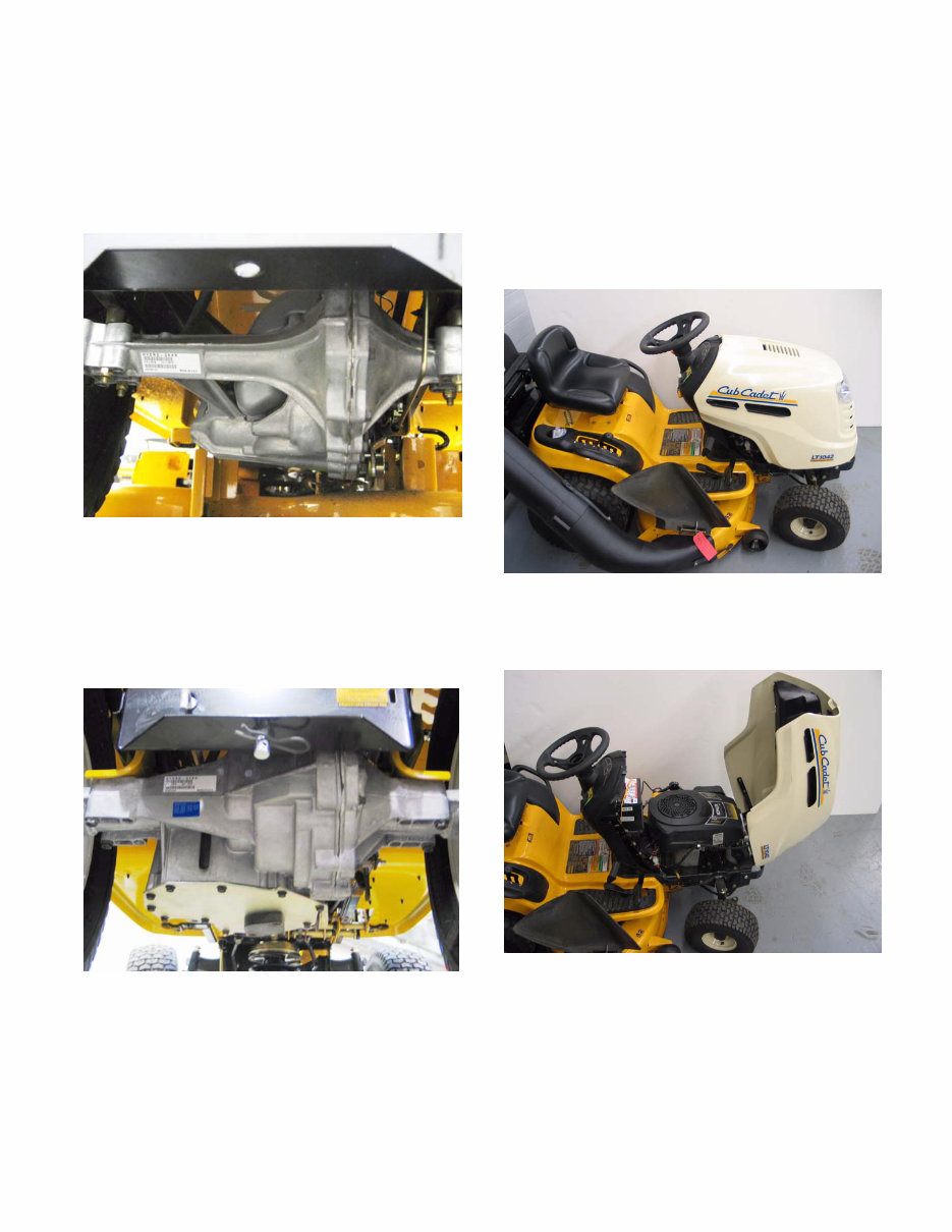
Series 1000 and 1500 3 1.15. A Hydro-Gear 314-0610 hydrostatic transaxle with a different final drive ratio is used on LT models having 22” rear tires. Hydrostatic tran- saxles have a rocker pedal to control forward and reverse direction and speed. See Figure 1.15. 1.16. A Hydro-Gear 320-3000 hydrostatic transaxle is used on GT designated models. This is a sub- stantially heavier duty IHT than the one used in the LT models. Hydrostatic transaxles have a rocker pedal to control forward and reverse direction and speed. See Figure 1.16. Figure 1.15 Figure 1.16 2. NEW HOOD DESIGN 2.1. Early 1000 and 1500 Series tractors used a vari- ety of steel hoods and side panels. Later ones resembled those used on the 2000 and 2500 Series tractors. 2.2. The hood presently used on the 1000 series tractors is a molded 1-piece design. See Figure 2.2. 2.3. The 1000 Series hood opens from the back. See Figure 2.3. Figure 2.2 Figure 2.3
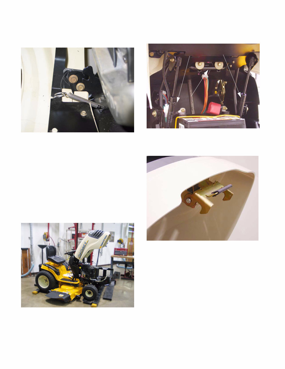
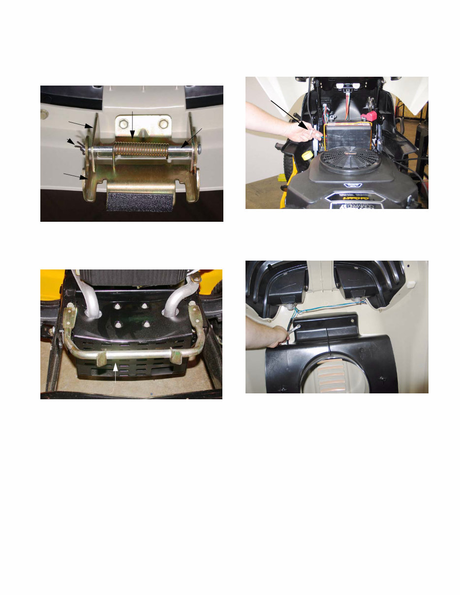
Series 1000 and 1500 4 2.4. The 1000 Series hood can be easily removed: See Figure 2.4. • Disconnect the headlight wires • Release the retaining springs • Align the bolts in the hood with the slots in the hinge. • Lifting the hood off of the tractor. 2.5. The hood used on the 1500 Series tractors for 2005 and 2006 is more substantial than that used on the 1000 Series. It is a one-piece molded design very similar to the one used on the much larger 5000 and 6000 series tractors. See Figure 2.5. • It opens from the front. • A pair of gas charged cylinders provide lift assist. See Figure 2.5. 2.6. A new spring-loaded latch was added to hold the hood closed. See Figure 2.6. Figure 2.4 Figure 2.5 Gas lift Cylinders Pivot Rod Figure 2.5 Figure 2.6
Series 1000 and 1500 5 2.7. A torsion spring keeps the latch secure until the lower pivot latch is intentionally pulled up, to open the hood. See Figure 2.7. 2.8. The hood latches to a sturdy rod that is mounted to the front of the frame. See Figure 2.8. 3. HOOD PANEL REMOVAL: 1500 SERIES NOTE: Use this procedure if the hood alone is to be removed. Typical reasons might include replacement because of damage to the hood, or to ease access for other service. 3.1. Disconnect ground cable from battery using a 7/16” wrench. Figure 2.7 Torsion Spring Cotter Lower Pivot Latch Upper Pivot Latch Pin Pivot Rod Figure 2.8 Hood Latch Rod 3.2. Disconnect headlight harness (plugged secured to hood lift cylinder). See Figure 3.2. 3.3. Remove the air deflector baffle using a 3/8” wrench. See Figure 3.3. 3.4. Support the hood as it is being loosened. 3.5. Separate hood from hinge using a 3/8” wrench. 3.6. Lift hood off of tractor. Figure 3.2 Headlight Harness Figure 3.3
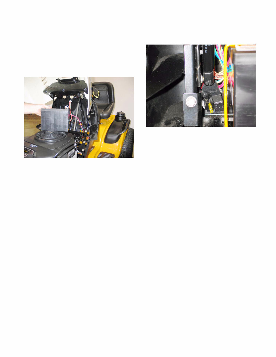
Series 1000 and 1500 6 4. HOOD AND HINGE REMOVAL: 1500 SERIES NOTE: Use this procedure for more extensive repairs. Typical reasons may include dash panel removal, or the need for more working room than simply removing the hood will provide. 4.1. Remove the battery: See Figure 4.1. • Disconnect the negative battery cable (black) first, using a 7/16” wrench. • Disconnect the positive battery cable (red) using a 7/16” wrench. • Remove the battery hold-down. • Lift the battery from the tractor. 4.2. Disconnect the headlight harness. (Plug secured to the hood lift cylinder). 4.3. Support the hood with an improvised prop-rod to prevent damage. 4.4. Remove screws holding hinge support bar to dash support using a 1/2” wrench. 4.5. Disconnect and remove the hood lift cylinders using a small straight-blade screwdriver. 4.6. Remove screws & flat washers holding hinge support bar to dash panel using a 3/8” wrench. 4.7. Lift hood and hinge assembly off of the tractor, and remove it to a safe place. 4.8. Hood installation notes: See Figure 4.8. • Position the hinge support bar over the two spacers that partially cover the threads of the balls that the that hood support struts attach to. The slots in the ends of the bar will fit over the spacers. • Support the hood with an improvised prop rod. • Install the screws that hold the hinge support bar to the dash support and instrument panel. • Snap the hood support cylinder into place, and remove the prop rod. • The remainder of the installation process is sim- ply the reversal of the removal steps. Figure 4.1 Figure 4.8
Upon purchasing this manual, you will receive a .PDF file containing an email contact. After contacting us, you will receive a reply with a link to access the manual for your Cub Cadet LT 1050.
This comprehensive manual covers every aspect of your machine, providing detailed guidance for tasks ranging from an oil change to a transmission swap. With hundreds of pages, it includes numerous illustrations and easy-to-understand instructions, making it useful for both professional mechanics and DIY enthusiasts. The manual also features a search function, allowing you to quickly find the information you need and print specific pages as required.
Designed as a Factory Service Repair Manual, it offers a step-by-step approach to maintaining and repairing your machine, equipping you with the knowledge that factory-trained technicians possess. By utilizing the insights provided in this manual, any owner can confidently make informed decisions about maintaining and repairing their equipment.
Our commitment extends beyond providing a high-quality service manual; we also ensure excellent customer service, guaranteeing your satisfaction.
Recently Viewed
5,521,897Happy Clients
2,594,462eManuals
1,120,453Trusted Sellers
15Years in Business
Price:
Actual Price:
Cub Cadet LT1050 Riding Tractors Service & Repair Manual