1 Chapter 1: Introduction.....................................................................................................1 Chapter 2 - Drive Sytem: CVT and Transfer Case............................................................9 Kohler Enclosed CVT Addendum..............................................................................63 Caterpillar Enclosed CVT Addendum........................................................................75 Chapter 3 - Drive System: Drive Shafts and Differentials................................................89 Chapter 4 - Front Suspension and Steering..................................................................123 Chapter 5 - Rear Suspension........................................................................................159 Chapter 6 - Hydraulic Brakes........................................................................................173 Chapter 7 - Kohler Engine Service Access and Fuel System........................................195 Kohler Engine Speed and Throttle Adjustment Addendum.....................................215 Chapter 8 - Caterpillar Engine and Related Systems....................................................219 Chapter 9 - Electrical.....................................................................................................275 Addendum - Front Drive System Differential Gearcase: Hillard.....................................323 Table of Contents
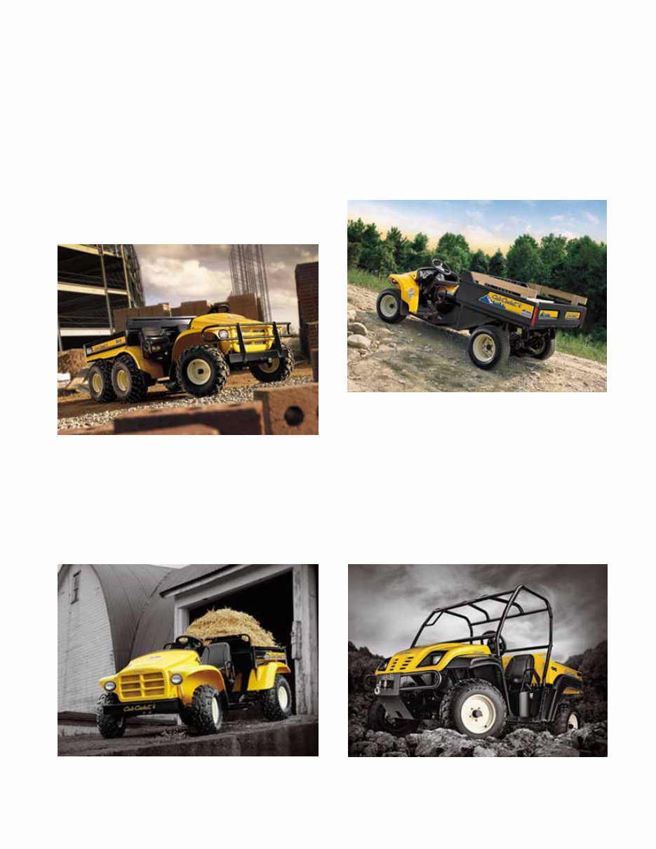
Chapter 1: Introduction 1 1. INTRODUCTION: PRODUCT LINE 6X4 Cub Cadet entered the utility vehicle market in the 2003 season with a 6X4 vehicle having fully indepen- dent suspension and Honda power (20 H.P.). The Big Country 6X4 continues in production with evolutionary changes and a switch to Kohler power. See Figure 1.1. Steel-bed 4X2 In 2004, a 4X2 vehicle was introduced. The 4X2 shares the 6X4 front suspension, has an 18 H.P. Honda engine and a push-button controlled transmis- sion. Evolutionary changes include a switch to Kohler power. See Figure 1.2. Big Country 6X4 Figure 1.1 Figure 1.2 4X2 Steel Bed Poly bed 4X2 For 2005, a lighter-duty version of the 4X2 was intro- duced, using a plastic cargo box and a 9.5 H.P. drives system sourced from Kawasaki. See Figure 1.3. All of these first-generation utility vehicles share a com- mon structure from the cargo box forward. The 6X4 carries a fully enclosed rear structure with swing-arm suspension. The 4X2s carry the engine and transaxles on a pivoting cradle that acts as the rear suspension. 4X4 The 4X4 vehicle that is the subject of this handbook represents a complete departure from the first genera- tion vehicles. See Figure 1.4. Figure 1.3 4X2 “Poly Bed” Figure 1.4 New 4X4 CHAPTER 1: INTRODUCTION
Chapter 1: Introduction 2 2. UNDERSTANDING UTILITY VEHICLE MODEL NUMBERS e.g.: 37AJ467D710 • 37 - - - - - - - - - indicates that this is a U.V. • - - A - - - - - - - - indicates the engineering level • - - - J - - - - - - - indicates the engine type • - - - - 4 - - - - - - indicates the number of wheels • - - - - - 67 - - - - indicates the series and trim • - - - - - - - D - - - indicates the type of tires • - - - - - - - - 710 indicates that it is Cub Cadet 2.1. Engine type detail: • B = Kohler Command 18 H.P. V-twin • C = Kohler Command 20 H.P. V-twin • J = Caterpillar Diesel 20 H.P. liquid cooled • N = Kawasaki 9.5 H.P. single, inclined • R = Honda 18 H.P. V-twin • S = Honda 20 H.P. V-twin 2.2. Series detail: • 1 = poly-bed 4 x 2 • 3 = steel bed 4 x 2 • 4 = 6 x 4 • 6 = 4 x 4 2.3. Trim detail: • 0 = yellow on 6 x 4 and 4 x 2 • 1 = camouflage on 6 x 4 and 4 x 2 • 2 = fire rescue red on 6 x 4 and 4 x 2 • 6 = yellow on 4 x 4 • 7 = camouflage on 4 x 4 2.4. Tires • A = turf tires • B = knobby tires • C = heavy-duty tires • D = trail tires • E = Fire Rescue: f. run-flat tires, r. trail tires • G = poly-bed trail tires 3. PROFESSIONAL SHOP MANUAL INTENT This Manual is intended to provide service dealers with an introduction to the mechanical aspects of the new vehicle. This Professional Shop Manual covers the second generation Cub Cadet Utility Vehicles more specifically, and in greater depth than the origanal Shop Handbook. • The content in this manual supersedes any con- tent in the handbook. • Detailed service information about the engine will be provided by the engine manufacturer, in most cases. Disclaimer: This manual was written using second generation vehicle. The information contained in this handbook is correct at the time of writing. Both the product and the information about the product are sub- ject to change without notice. About the text format: NOTE: is used to point-out information that is relevant to the procedure, but does not fit as a step in the procedure. CAUTION: is used to point-out potential danger to the technician, operator, bystanders, or sur- rounding property. • Bullet points: indicate sub-steps or points. Disclaimer: This Professional Shop Manual is intended for use by trained, professional technicians. • Common sense in operation and safety is assumed. • In no event shall MTD or Cub Cadet be liable for poor text interpretation, or poor execution of the procedures described in the text. • If the person using this manual is uncomfortable with any procedures they encounter, they should seek the help of a qualified technician or Cub Cadet Technical Support.
Chapter 1: Introduction 3 Fasteners: • Most of the fasteners used on the vehicle are sized in fractional inches. Some are metric. For this reason, wrench sizes are frequently identified in the text, and measurements are given in U.S. and metric scales. • If a fastener has a locking feature that has worn, replace the fastener or apply a small amount of releasable thread locking compound such as Loctite® 242 (blue). • Some fasteners like cotter pins are single-use items that are not to be reused. Other fasteners such as lock washers, retaining rings, and internal cotter pins (hairpin clips) may be reused if the do not show signs of wear or damage. This manual leaves that decision to the judgement of the technician. Assembly: Torque specifications may be noted in the part of the text that covers assembly, they may also be summa- rized in tables along with special instructions regarding locking or lubrication. Whichever method is more appropriate will be used. In many cases, both will be used so that the manual is handy as a quick-reference guide as well as a step-by- step procedure guide that does not require the user to hunt for information. The level of assembly instructions provided will be determined by the complexity and of reassembly, and by the potential for unsafe conditions to arise from mis- takes made in assembly. Some instructions may refer to other parts of the man- ual for subsidiary procedures. This avoids repeating the same procedure two or three times in the manual. 4. LIFTING AND SUPPORTING CAUTION: Use common sense and safety when lifting and supporting any equipment: • Always work on a firm, level surface that will support the load to be placed on it. • Never leave equipment supported by hydraulic means: hydraulic jacks are for lifting. Once lifted, the equipment should be positioned on and supported by jack stands of sufficient capac- ity to ensure safety. • Confirm that the equipment is firmly seated on the jack stands before doing any work that results in exposure to falling or crushing hazard. • Use caution when positioning jacks and jack stands, so as not to damage any fuel lines, brake lines, electrical conduits, or linkages. • Do not lift or support the vehicle by the cradle that the engine and transfer case are mounted to. It is vibration-isolated from the rest of the vehicle. The rubber isolator mounts are not designed to support the weight of the vehicle. The utility vehicle may be lifted from the rear by placing a jack under the rear-most cross-member. This cross- member also provides a mounting point for the 2” class 1 hitch receiver. See Figure 1.5. Figure 1.5 Rear cross-member Accessory receiver
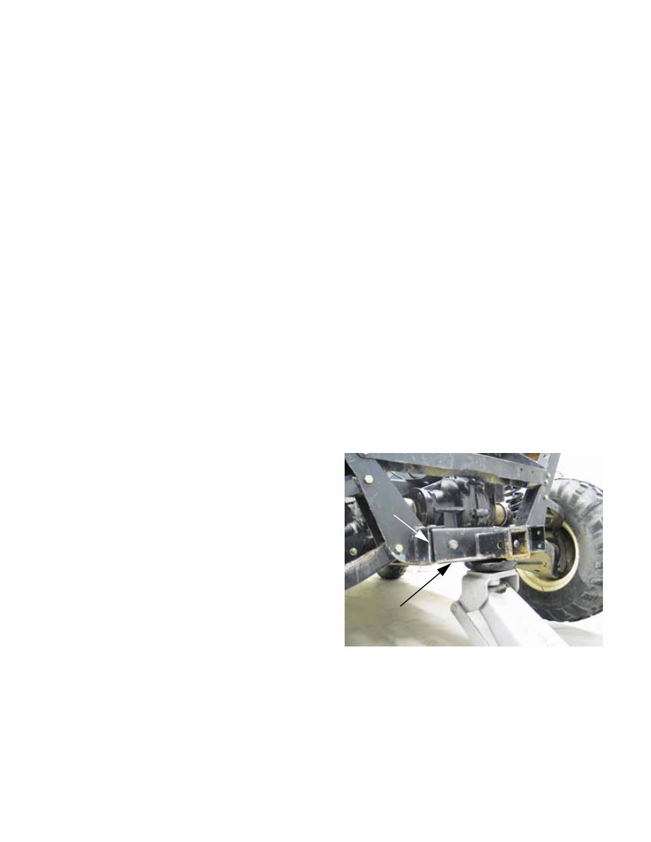
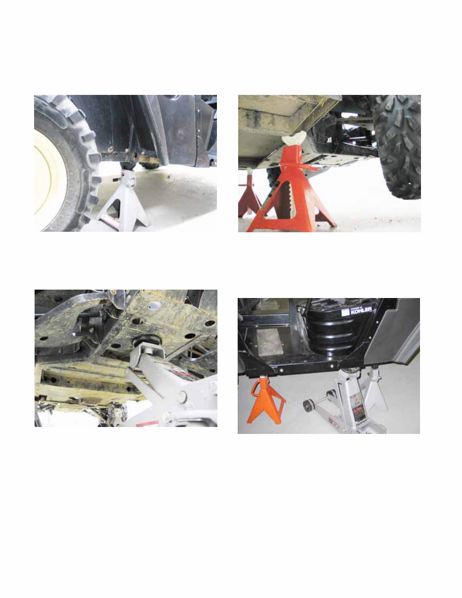
Chapter 1: Introduction 4 Jack stands can safely be positioned beneath the up- right frame members that are roughly even with the centerline of the tray that supports the engine and transfer case. See Figure 1.6. The front of the vehicle may be safely lifted by placing a jack directly under the mounting point where the front differential joins the frame. See Figure 1.7. Jack stands will safely support the front of the vehicle if positioned beneath the frame, where the front out-rig- ger extends to meet the base of the OPS. See Figure 1.8. Alternatively, the vehicle may be lifted by positioning a jack along the outer frame channel, where the rear out-rigger extends to meet the base of the OPS . See Figure 1.9. NOTE: The center of gravity for the vehicle is beneath the seat support structure. NOTE: The outer frame channel will support the vehicle without damage. Figure 1.6 Figure 1.7 Figure 1.8 Figure 1.9
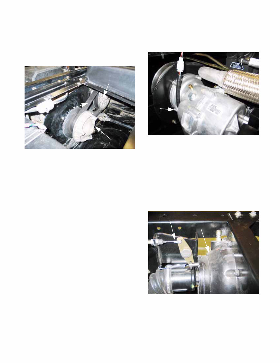
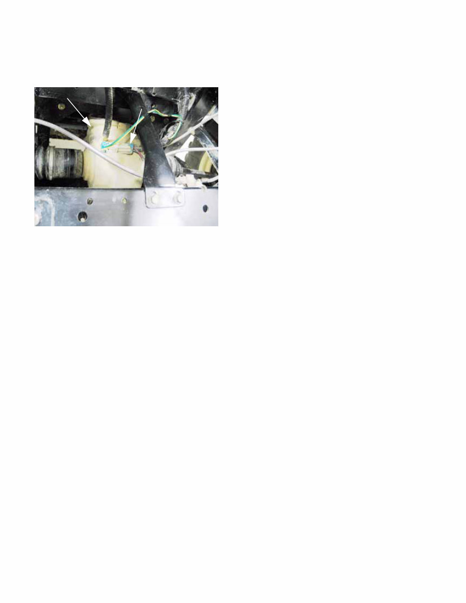
Chapter 1: Introduction 5 5. DRIVE SYSTEM DESCRIPTION • A belt-type CVT (Continuously Variable Trans- mission) system carries power from the engine crankshaft to the transfer case. See Figure 1.10. • The CVT range provides strong torque and acceleration, limiting speed to 25 MPH (40 KPH). • The driving clutch on the engine crankshaft uses centrifugal force to operate a mechanism that pulls the sheaves closer together. The faster the engine spins, the closer the sheaves get. As the sheaves close-down on the belt, the belt is forced outward. As the belt is forced outward, the drive ratio decreases so that fewer crankshaft revolutions equate to more input shaft revolutions at the input shaft of the transfer case. NOTE: A lower numeric ratio results is fre- quently referred to as a “steeper” or “taller” drive ratio, yielding in increased top speed. • As the effective diameter of the driving pulley increases, the belt has less available length to reach the driven pulley. The sheaves of the driven pulley is spring- loaded so that it can absorb the additional ten- sion. An additional effect is that the belt is drawn deeper into the sheaves, reducing the effective diameter of the driven pulley. Reducing the diameter of the driven pulley fur- ther reduces the drive ratio. Figure 1.10 CVT driving element CVT belt CVT driven element • The transfer case is mounted adjacent to the engine, with the input shaft running fore-and-aft in the frame. See Figure 1.11. • The transfer case contains two forward ratios, neutral, and reveres. • Gear selection is controlled by rods and a selec- tor lever sourced from Hurst®. Drive shafts with Hooke/Spicer type universal joints extend fore and aft from the output shafts of the trans- fer case to drive the front and rear differentials. The rear differential has a cast iron housing and a cable-actuated locking feature. See Figure 1.12. Figure 1.11 Transfer case Figure 1.12 Differential lock actuator Rear differential
Chapter 1: Introduction 6 The front differential has an aluminum housing, and an electronically controlled, slip sensing Auto-Lok® feature. See Figure 1.13. • The front differential is engaged or disengaged using a rocker switch on the dashboard. Each differential transfers power to the drive hubs through a drive shaft with Rzeppa-type constant veloc- ity joints at each end. 6. SERVICE INTENT The transfer case is manufactured by Cub Cadet. If it fails during the first year , it should be removed and replaced as a complete unit. • In the event of a failure, the transfer case will be called back for engineering analysis. • If the failure is warrantable, Cub Cadet will cover the cost of replacement. • If the failure is not warrantable, replacement will be at the customer’s expense. • Beyond the first year, but within the first two years, the decision whether to repair or replace the transfer case will be based on economic fea- sibility and the availability of parts and assem- blies. • Beyond the warranty period, the dealer can repair or replace the transfer case at their own discretion. The remainder of the drive system (CVT, drive shafts, axles, differentials) is purchased from outside ven- dors. • If any of these items fail in the first two years, they should be removed and replaced with a complete unit. The only exception to this may be the axles. Rzeppa (Constant Velocity) joints may be available to repair rather than replace axles. Service intent has not been decided as this manual goes to print. • In the event of a failure, the component will be called back for engineering analysis and vendor recovery. • If the failure is warrantable, Cub Cadet will cover the cost of replacement. • If the failure is not warrantable, replacement will be at the customer’s expense. • Beyond the warranty period, internal parts for the differentials will be made available so that the dealer can repair or replace them at their own discretion. Kohler Engines will be serviced as they are in the rest of the Cub Cadet product Line. They are seen as an integral part of the Cub cadet product, with parts and warranty coverage provided through Cub Cadet. Caterpillar Engines in Cub cadet equipment will con- tinue to be serviced exclusively by CAT dealers. Figure 1.13 Front differential Electrical connection for Auto-Lok® feature
The Cub Cadet 4x4 UTVs OEM Service & Repair Manual gives you the factory procedures needed to keep these machines working hard. Written for dealership techs but approachable for a hands-on DIY owner, it walks through every system from routine service to full component rebuilds.
The manual lays out step-by-step coverage for the CVT and transfer case, including both Kohler and Caterpillar enclosed CVT units. It also covers drivetrain service like driveshaft and differential repair, plus suspension work on both the front and rear. Hydraulic brake troubleshooting and steering system adjustments are explained with clear specs and inspection points.
Content overview:
Introduction to vehicle specifications and manual structure
CVT and transfer case service, including Kohler and Caterpillar enclosed CVT systems
Drive shaft and differential repair procedures
Front suspension and steering system diagnostics and maintenance
Rear suspension system inspection and service steps
Hydraulic brake system servicing and troubleshooting
Kohler engine service access and fuel system maintenance
Caterpillar engine system diagnostics and related servicing
Complete electrical system diagrams, testing, and repair instructions
Addendum: Hillard front drive system differential gearcase servicing
Engine maintenance is detailed for Kohler-equipped models, with Caterpillar system diagnostics also included. Fuel system checks, service intervals, and repair guidelines are supported by electrical testing procedures and component repair steps. An addendum on the Hillard front drive system rounds out the reference for complete UTV servicing.
Printable: Yes Language: English Compatibility: Pretty much any electronic device, incl. PC & Mac computers, Android and Apple smartphones & tablet, etc. Requirements: Adobe Reader (free)