Series 3000 Technical Handbook Table of Contents Section Pre-Delivery Check List and Service Specifications 1999 ................................................................................1 Engineering Updates 1999................................................................................................................................2 Fender Removal and Reinstallation ..................................................................................................................3 Hydraulic Step by Step Flow Charts .................................................................................................................4 Power Steering Cylinder Removal and Replacement .......................................................................................5 Power Steering Pump Disassemble, Inspect and Reassemble ........................................................................6 Center Lift Cylinder Removal and Replacement ...............................................................................................7 Pump Adapter Removal and Replacement .......................................................................................................8 BDU-21L-500 Pressure Test Procedure ...........................................................................................................9 Hydraulic Steering Pump Removal and Replacement ....................................................................................10 Hydraulic Valve Removal and Replacement ...................................................................................................11 Engine Removal and Replacement .................................................................................................................12 Transmission Removal and Installation ..........................................................................................................13 Transmission Inspection and Disassembly .....................................................................................................14 Transmission Reassembly (Cast Iron Transmission Addendum). .................................................................15 Neutral Control Adjustment .............................................................................................................................16 3000 Series Electrical .....................................................................................................................................17 BDU-21L Transmission ...................................................................................................................................18
1 - 1 3000 Series Pre-Delivery Check List CUSTOMER NAME_____________________________________ MODEL NUMBER _________________________ CUSTOMER ADDRESS__________________________________ SERIAL NUMBER _________________________ CITY_______________________ STATE______ ZIP__________ TECHNICIAN ____________________________ ENGINE INFORMATION TRANSMISSION INFORMATION Engine Make __________________ Transmission make __________________ Model No. __________________ Model No. __________________ Serial No. __________________ Serial No. __________________ Spec No. __________________ CUSTOMER SIGNATURE_________________________________________________ DATE__________________ Operator’s Manual Complete? ❑ Owners Manual ❑ Attachment Guide ❑ Merchandising Catalog Battery and connections ❑ Remove battery and fill to proper level ❑ Allow battery to stand for 30 minutes ❑ Charge at 4 AMPS max. to 1.265 specific gravity Tire Pressure ❑ Front ❑ Rear *Refer to owners manual for proper PSI Check all lights and indicators ❑ Headlights, Tail and Backup lights ❑ Low oil light ❑ Hour meter Lubrication ❑ Transmission oil level ❑ Engine oil level *Check tractor owners manual for type and grade Air cleaner and connections ❑ Remove air cleaner cover to verify air cleaner is installed ❑ Insure retaining bolt seal is installed ❑ Insure proper installation of breather hose ❑ Proper operation of throttle and choke cables Steering ❑ Check for 1/8 to 1/4 inch toe in. ❑ Insure equal travel right and left ❑ Check steering wheel tilt Hydrostatic / Gear drive and brakes ❑ Check brakes ❑ Check for neutral when brake pedal is depressed ❑ Check for neutral when forward and reverse pedals are released ❑ Check cruise control Grease pivot points ❑ Front axle pivot bar ❑ Each steering knuckle ❑ Each front wheel ❑ Steering housing ❑ All grease points on mower deck *Refer to specific mower owners manual Install attachments mower / snow blower etc. ❑ Check PTO ❑ Inspect linkage ❑ Deck level adjustment Safety operations ❑ Check no cut in reverse ❑ Check engine shutdown with PTO engaged and seat empty ❑ Check engine shutdown with empty seat and parking brake not engaged Check engine speeds / Controls ❑ Low idle - 1200 RPM ❑ High idle - 3600 RPM Final inspection ❑ Overall appearance ❑ Clean and polish Hydraulics ❑ Check lift valve ❑ Check lift cylinder
1999 Specifications 1 - 2 Cub Cadet 1999 Specifications SERIES 3000 TRACTORS Features and General Specifications: • Hydrostatic Drive w/Cruise Control • Cast Iron Front Axle • Shaft Drive Transmission • 4.5 Gallon Fuel Tank • Shaft Drive Deck and Front Attachments • E-Vac PTO System • Power Steering • Tilt Steering Wheel • Hydraulic Lift • Differential Lock (3205, 3225) • Welded Full Length Twin Channel, 9 gauge • Speed: Steel Frame – 0-7 MPH Forward • Deck Height Indicator – 0-4 MPH Reverse • Halogen Headlights • Tires: • Taillights w/Reverse Lights – 16" x 7.5" Front • 27" Turning Radius – 24" x 10.5" Rear Model Factory No. Series 3000 3165 14A-654-100 16.0 HP B&S Twin Vanguard OHV, Hydro, Power Steering, Power Lift 3185* 14A-665-100 18.0 HP B&S Twin Vanguard, Hydro, Power Steering, Power LIft 3186 14A-668-100 18.0 HP Kohler V-Twin OHV, Hydro, Power Steering, Power Lift 3205 14A-685-100 20.0 HP Liquid Cooled V-Twin Kawasaki OHV, Power Steering, Power Lift, Differential Lock 3225 14A-688-100 22.0 HP V-Twin Kohler OHV, Power Steering, Power Lift, Differential Lock *Limited Quantities Available Model Factory No. Attachments and Accessories 345 190-345-100 Fan Assist Bagger for 48"/54" Deck 289 190-289-100 48" Deck, Shaft Driven 290 190-290-100 54" Deck, Shaft Driven 291 190-291-100 60" Deck, Shaft Driven (3205 & 3225 only) 343 190-343-100 Hydraulic Front Hitch System 352 190-352-100 54" Front Mounted Snow Blade (Requires 343; Optional 288 or 171) 353 190-353-100 45" Snow Thrower, Shaft Driven (Req. 343) 299 190-299-100 Ag Tires/Rims 23" x 8.5" 249 190-249-100 Ag Tires/Rims 23" x 10.5" 366 190-366-100 Rear Turf Tires/Rims 24" x 10.5" 365 190-365-100 Hydraulic 3 Pt. Hitch, Category “O” 924 190-924-100 ‘A’ Frame Hitch Adapter, Converts Sleeve Hitch Attachments To Cat. “O” 3-Pt. Hitch 163 190-163-100 42"' Lawn Sweeper 653 190-653-100 10 Cu. Ft. Cart 368 190-368-100 10 Cu. Ft. Heavy Duty Dump Cart 425 190-425-100 17 Cu. Ft. Heavy Duty Dump Cart 161 190-161-000 48" Poly Bed Liner (Fits All 10’s) (Tailgate Section Must Be Cut Out By Dealer)
1 - 3 1999 Specifications Model Factory No. Attachments and Accessories 162 190-162-000 60" Poly Bed Liner (Fits All 17’s) (Tailgate Section Must Be Cut Out By Dealer 288 190-288-100 Hydraulic Front Angle Kit (Cannot Be Used w/353) 171 190-171-100 Manual Angle Kit (Cannot Be Used w/353) 412 190-412-100 Rear Wheel Weights (2 per Set) @ 75# 413 190-413-100 Front & Rear Wt. Bracket (Supports 390 Wt.) 190390 190-390-100 Suitcase Weights 506 590-605-100 Mulcher, 48" Deck+ 507 590-507-100 Mulcher, 54" Deck++ 920 190-920-000 12" Mold Board Plow (Requires 365) 921 190-921-000 Tandem Disc (Requires 365) 922 190-922-000 Spring Cultivator (Requires 365) 400 190-400-100 38" Tiller, 8.0 HP B&S Engine (Requires 365) 206 190-206-100 Series 3000 Tractor Display Stand NOTES: + To Mount on Series 3000 Deck You Must Order Qty. 1 - 603-0624 and 1- 603-0625 From Parts ++ To Mount on Series 3000 Deck You Must Order Qty. 1- 603-0626 and 1- 603-0627 From Parts It is recommended that the 3165 be equipped with a 48" deck for maximum performance. Cub Cadet 1999 Specifications (continued)
NOTES
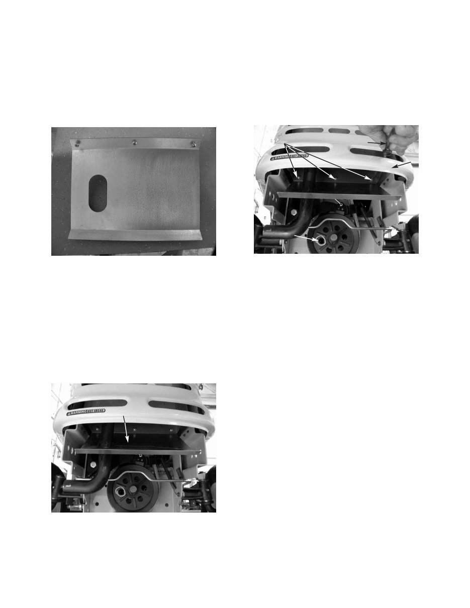
2 - 1 Cub Cadet 3000 1999 3000 Series Engineering Updates 1. Remove both of the hex bolts and lock nuts securing the front bumper to the frame using a 3/4" socket and a 3/4" wrench. 2. Remove the bumper. 3. Slide the muffler shield over the exhaust pipe and rotate it into position. NOTE: Align all three holes in the top of the muffler shield with the existing shield. Also, the muffler shield will be slanting towards the bottom of the front grill assembly. Heat Shield Heat Shield HEAT SHIELD A heat shield has been installed on all 3000 series tractors for 1999. The heat shield prevents the exhaust gases from browning the grass. Use kit #759- 3927. See Service Advisory CC-371. LIFT LINK The lift link has been modified by strengthening the powder metal that connects the lift lever to the hydraulic valve for 1999. CHECK VALVE For 1999, a check valve will be installed to the hydraulic valve to prevent the decks and other attach- ments from leaking down during and after usage. LIFT STOP BRACKET A lift stop bracket will be installed on the left hand side of the deck to prevent the deck from hanging up dur- ing operations. Use kit #759-3927. ROLLER HEIGHT ADJUSTER The rear roller height adjustment mechanism will be changed for 1999. A newly designed detent pin will replace the old one, preventing the loss of cutting height during operations. Use kit #759-3928. FRONT DECK HANGER ASSEMBLY The front roller bracket has been redesigned to pre- vent the front lift rod from detaching during operation. SEAT IMPROVEMENTS A safer seat spring, part number 732-0869, can be installed to level the seat for petite operators. In addi- tion, the seat part number 757-3010A, is now made out of a softer material for better operator comfort. See Service Advisory CC-358A Sections 5 and 6. FRONT MOWER DECK HEIGHT ADJUSTER The front mower deck height adjuster pins have been changed from ball detent pins to quick pull pins. Sheet Metal Screws Screwdriver Grill Mark used in Production to Test PTO Activation 4. Secure the muffler shield with three sheet metal screws. NOTE: Use a long flat blade screwdriver through the air holes in the grill to tighten the sheet metal screws securely. 5. Install the bumper.
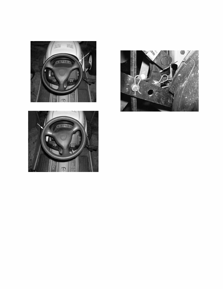
2 - 2 Cub Cadet 3000 STEERING WHEEL The thickness of the steering wheel has been increased for operator comfort. New Thicker Steering Wheel Steering Wheel Thicker Old Style Steering Wheel Steering Wheel Thinner ROCK SHAFT ASSEMBLY FOR 3 POINT HITCH 190-365-100 The cylinder arms have been redesigned with two V sections cut out to allow for clearance of the clevis nut on the cylinder shaft. See Service Advisory CC-364. 3000 Series Lift Assembly Grooved Out Area
2 - 3 Cub Cadet 3000
You're Reading a Preview
What's Included?
Lifetime Access
Fast Download Speeds
Online & Offline Access
Access PDF Contents & Bookmarks
Full Search Facility
Print one or all pages of your manual
$36.99
Cub Cadet 3000 series tractors, mower decks attachments Service Repair Workshop Manual INSTANT
Complete service repair manual for the Cub Cadet 3000 series tractors, including riding mower decks 3165, 3185, 3186, 3205, and 3225, which also covers the cast iron transmission manual.
No shipping involved, and you can access it instantly without waiting for the mailman. This manual is used by dealerships and professional mechanics for fixing outdoor power equipment. It covers general information, dealer preparation, preventive maintenance, troubleshooting and testing, adjustments, attachments, electrical, and other topics.
Print only the section you need and discard it after use, or print the entire manual and keep it in a 3-ring binder for reference. These manuals are in Adobe Acrobat format and are compatible with both PC and Mac. Instant delivery ensures no waiting for a CD to arrive via mail.
*Note: High-speed internet users only. Some files may be too large for dial-up users. Please message for file size compatibility with dial-up connections.
Reviews
Q&A
Recently Viewed
5,521,897Happy Clients
2,594,462eManuals
1,120,453Trusted Sellers
15Years in Business
Price:
Actual Price:
Cub Cadet 3000 series tractors, mower decks attachments Service Repair Workshop Manual INSTANT










 Lifetime Access




