


Service Manual
1000/1500 Series Riding Tractors
MTD Products Inc. - Product Training and Education Department
FORM NUMBER - 769-02100
1/2006
NOTE: These materials are for use by trained technicians who are experienced in the service and repair of outdoor power
equipment of the kind described in this publication, and are not intended for use by untrained or inexperienced individuals.
These materials are intended to provide supplemental information to assist the trained technician. Untrained or inexperi-
enced individuals should seek the assistance of an experienced and trained professional. Read, understand, and follow all
instructions and use common sense when working on power equipment. This includes the contents of the product’s Oper-
ators Manual, supplied with the equipment. No liability can be accepted for any inaccuracies or omission in this publication,
although care has been taken to make it as complete and accurate as possible at the time of publication. However, due to
the variety of outdoor power equipment and continuing product changes that occur over time, updates will be made to these
instructions from time to time. Therefore, it may be necessary to obtain the latest materials before servicing or repairing a
product. The company reserves the right to make changes at any time to this publication without prior notice and without
incurring an obligation to make such changes to previously published versions. Instructions, photographs and illustrations
used in this publication are for reference use only and may not depict actual model and component parts.
© Copyright 2006 MTD Products Inc. All Rights Reserved


1
1. INTRODUCTION ........................................................................................................................ 1
2. NEW HOOD DESIGN ................................................................................................................. 3
3. HOOD PANEL REMOVAL: 1500 SERIES ................................................................................ 5
4. HOOD AND HINGE REMOVAL: 1500 SERIES ........................................................................ 6
5. REAR FENDER REMOVAL ....................................................................................................... 7
6. FUEL SYSTEM ........................................................................................................................... 9
7. FUEL SHUT-OFF SOLENOID ................................................................................................. 11
8. FUEL RELATED NO-START ISSUES ..................................................................................... 11
9. MUFFLER REMOVAL .............................................................................................................. 12
10. CUTTING DECK REMOVAL .................................................................................................... 13
11. DECK LIFT SHAFT ASSEMBLY ............................................................................................. 15
12. LIFT SHAFT BUSHINGS ......................................................................................................... 16
13. DECK LIFT CABLES AND PULLEYS ..................................................................................... 17
14. LEVELING THE CUTTING DECK ........................................................................................... 18
15. DASH PANEL REMOVAL ....................................................................................................... 20
16. CRUISE CONTROL AND PARK BRAKE LINKAGES ............................................................ 22
17. TRACTION DRIVE BELT REPLACEMENT: CVT ................................................................... 24
18. DRIVE SYSTEM ADJUSTMENT: CVT .................................................................................... 27
19. BRAKE ADJUSTMENT: CVT .................................................................................................. 30
20. SERVICING THE BRAKE PEDAL SHAFT BUSHINGS: ......................................................... 32
21. TRANSAXLE REPLACEMENT: CVT ...................................................................................... 34
22. TRANSAXLE SERVICE AND INTERNALS: CVT ................................................................... 36
23. TRACTION DRIVE BELT REPLACEMENT: HYDROSTATIC LT ........................................... 36
24. DRIVE SYSTEM ADJUSTMENT: HYDROSTATIC LT ........................................................... 39
25. HYDRO CONTROL ROD ADJUSTMENT ............................................................................... 42
26. BRAKES AND BRAKE ADJUSTMENT: HYDROSTATIC LT ................................................. 43
27. PEDAL BUSHING REPLACEMENT ........................................................................................ 46
28. TRANSAXLE SERVICE AND MAINTENANCE: HYDROSTATIC LT ...................................... 47
29. TRANSAXLE REPLACEMENT: HYDROSTATIC LT .............................................................. 49
30. TRACTION DRIVE BELT REPLACEMENT: HYDROSTATIC GT ........................................... 52
31. DRIVE SYSTEM ADJUSTMENT: HYDROSTATIC GT............................................................ 54
32. BRAKES AND BRAKE ADJUSTMENT: HYDROSTATIC GT ................................................. 58
33. TRANSAXLE SERVICE AND MAINTENANCE: HYDROSTATIC GT ..................................... 62
34. TRANSAXLE REPLACEMENT: HYDROSTATIC GT .............................................................. 64
35. STEERING GEAR AND STEERING PINION GEAR REPLACEMENT ................................... 67
36. STEERING ADJUSTMENT / ALIGNMENT ............................................................................. 68
37. PIVOT BAR SERVICE ............................................................................................................. 69
38. ELECTRICAL SYSTEM ........................................................................................................... 71
39. UNDERSTANDING THE PTO SWITCH ................................................................................... 77
Table of Contents

2
Series 1000 and 1500
1
1. INTRODUCTION
Disclaimer: This service manual is intended to be
used by trained technicians.
Disclaimer: The information contained in this manual
is current and accurate at the time of writing, but is sub-
ject to change without notice.
1.1. Intent: This manual is intended to:
• Provide specific service and repair procedures
for a range of Cub Cadet 1000 and 1500 Series
tractors manufactured for the 2005/2006 sea-
son.
• Highlight significant changes to the Cub Cadet
1000 Series since it’s introduction.
1.2. Engines: A variety of single cylinder and V-twin
engines have been used in the 1000 series trac-
tors. Kohler Courage line of single-cylinder and
V-Twin engines is presently the most heavily
used power source in the 1000 Series line
1.3. For specific engine service information, refer to
the engine manufacturer’s service publications.
1.4. The engine is partially identified by the 4th digit
of the factory number:
• 13AX 11CG756 - Kohler Courage single cylinder
• 13AP 11CP756 - Kohler courage V-Twin
1.5. Refer to the table provided for engine applica-
tions in the 1000 series range. See Figure 1.5.
Year Model # Factory # Engine
2001 1027 13A-328-101 9.0 HP BS
1170 13CD608G101 17.5 HP BS
1180 13AT608H101 18 HP BS
1212 14AJ808H101 21 HP BS
2002 1027 13A-328-101 9.0 HP BS
1170 13CD608G101 17.5 HP BS
1515 13A-201F100 15 HP KOH
1517 13A-231G100 17 HP KOH
2003 1525 13A-221F100 15 HP KAW
1527 13A-241G100 17 HP KAW
1529 13A-261H100 19 HP KAW
2004 LT 1018 13AL11CG710 18.5 HP BS
LT 1022 13AB11CH710 22 HP BS
LT 1024 13AR11CP710 24 HP BS
GT 1222 14AB13CH710 22 HP BS
2005 LT 1042 13BX11CG710 19 HP KOH
LT 1045 13AX11CH710 20 HP KOH
LT 1046 13AP11CH710 23 HP KOH
LT 1050 13AQ11CP71 0 26 HP KOH
SLT 1554 13AK11CK710 27 HP KOH
2006 LT 1042 13AX11CG756 19 HP HOH
LT 1045 13AX11CH756 20 HP KOH
LT 1050 13AP11CP756 23 HP KOH
SLT 1550 13AQ11BP756 25 HP KOH
GT 1554 14AK13BK756 27 HP KOH
1000 Series Engine Applications
Figure 1.5
Series 1000 and 1500
Series 1000 and 1500
2
1.6. Decks: Cutting decks ranging in width from 38”
to 54” have been used on the 1000 Series plat-
form.
1.7. There have been multiple versions of some
decks, most particularly the 42”. Check the serial
number when researching for parts or service
information.
1.8. The deck size is identified by the 8th digit of the
factory number: See Figure 1.8.
• 13AX11CG 756 - 42” 2-blade deck
• 13AX11CH 756 - 46” 3-blade deck
• 13AP11CP 756 - 50” 3-blade deck
• 13AQ11BP 756 - 50” 3-blade deck
• 14AK13BK 756 - 54” 3-blade deck
1.9. Drive Systems: A variety of hydrostatic and
CVT drive systems have been used on the 1000
Series tractors.
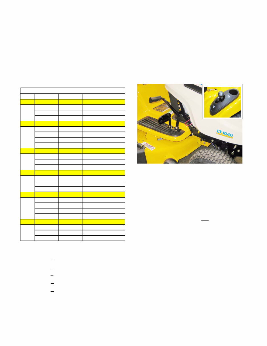
1.10. A Two-belt CVT system driving an MTD single-
speed transaxle is presently used only on the
LT1040 model. This system can be distin-
guished by the gear selector (F-N-R) on the left
rear fender, and the simple drive pedal.
See Figure 1.10.
1.11. A similar two-belt CVT system was employed to
drive a heavy-duty transaxle in some 2002 and
2002 models having two forward speed ranges.
These are easy to identify by the presence of the
gear selector lever between the operators knees
rather than on the fender.
1.12. All CVT driven 1000 and 1500 Series tractors
have a gear selector lever and a drive pedal on
the right side, near the brake pedal.
1.13. All Hydrostatic transaxles on the 1000 and 1500
Series are operated by a rocker pedal on the
right side, near the brake pedal.
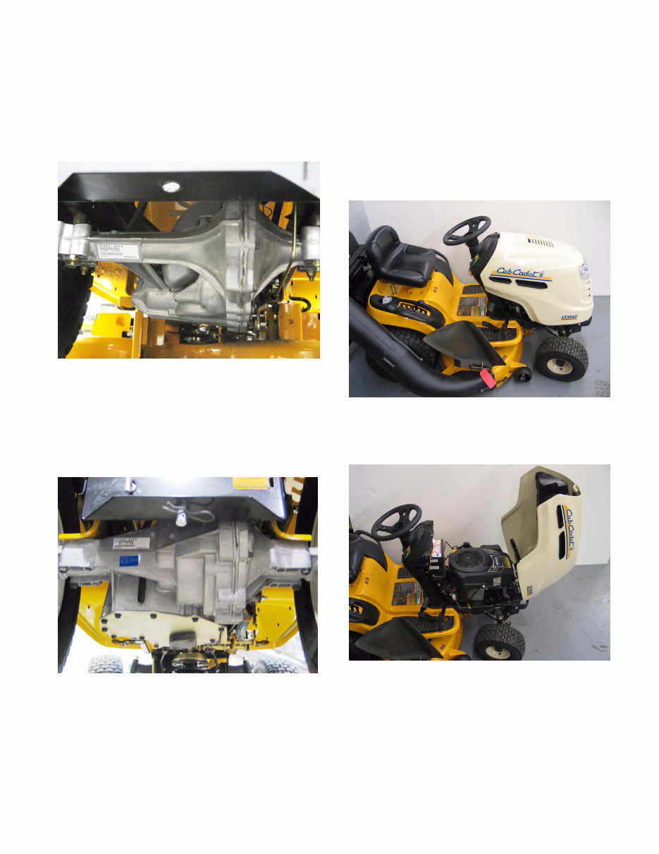
1.14. A Hydro-Gear 310-0510 hydrostatic transaxle is
used on LT models having 20” rear tires. Hydro-
static transaxles have a rocker pedal to control
forward and reverse direction and speed.
Figure 1.8
Year Width Deck Deck/PTO Belts
2001 27.5" CYB/STD 754-0754
42" G 754-0472
46" H 754-0349/754-0476
2002 27.5" CYB/STD 754-0754
42" G 754-0472
38" F 754-0641
42" G 754-0645/754-0644
2003 38" F 754-0641
42" G 754-0645/754-0644
46" H 754-04011
2004 42" G 754-0498/754-0499
46" H 754-04033
50" P 754-04048
2005 42" G 754-04060B
46" H 754-04033
50" P 754-04077
54" K 754-0642
2006 42" G 754-0349
46" H 754-0349
50" P 754-0349
54" K 754-0349
1000 Series Deck Applications
Figure 1.10
Series 1000 and 1500
3
1.15. A Hydro-Gear 314-0610 hydrostatic transaxle
with a different final drive ratio is used on LT
models having 22” rear tires. Hydrostatic tran-
saxles have a rocker pedal to control forward
and reverse direction and speed. See Figure
1.15.
1.16. A Hydro-Gear 320-3000 hydrostatic transaxle is
used on GT designated models. This is a sub-
stantially heavier duty IHT than the one used in
the LT models. Hydrostatic transaxles have a
rocker pedal to control forward and reverse
direction and speed. See Figure 1.16.
Figure 1.15
Figure 1.16
2. NEW HOOD DESIGN
2.1. Early 1000 and 1500 Series tractors used a vari-
ety of steel hoods and side panels. Later ones
resembled those used on the 2000 and 2500
Series tractors.
2.2. The hood presently used on the 1000 series
tractors is a molded 1-piece design. See Figure
2.2.
2.3. The 1000 Series hood opens from the back.
See Figure 2.3.
Figure 2.2
Figure 2.3
Series 1000 and 1500
4
2.4. The 1000 Series hood can be easily removed:
See Figure 2.4.
• Disconnect the headlight wires
• Release the retaining springs
• Align the bolts in the hood with the slots in the
hinge.
• Lifting the hood off of the tractor.
2.5. The hood used on the 1500 Series tractors for
2005 and 2006 is more substantial than that
used on the 1000 Series. It is a one-piece
molded design very similar to the one used on
the much larger 5000 and 6000 series tractors.
See Figure 2.5.
• It opens from the front.
• A pair of gas charged cylinders provide lift assist.
See Figure 2.5.
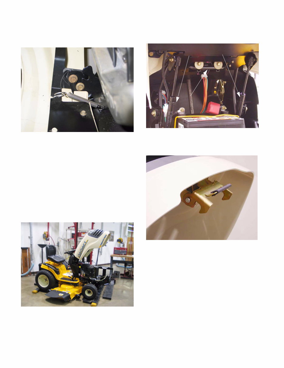
2.6. A new spring-loaded latch was added to hold the
hood closed. See Figure 2.6.
Figure 2.4
Figure 2.5
Gas lift Cylinders
Pivot Rod
Figure 2.5
Figure 2.6

Series 1000 and 1500
5
2.7. A torsion spring keeps the latch secure until the
lower pivot latch is intentionally pulled up, to
open the hood. See Figure 2.7.
2.8. The hood latches to a sturdy rod that is mounted
to the front of the frame. See Figure 2.8.
3. HOOD PANEL REMOVAL: 1500 SERIES
NOTE: Use this procedure if the hood alone is to
be removed. Typical reasons might include
replacement because of damage to the hood, or
to ease access for other service.
3.1. Disconnect ground cable from battery using a
7/16” wrench.
Figure 2.7
Torsion Spring
Cotter
Lower
Pivot
Latch
Upper
Pivot
Latch
Pin
Pivot
Rod
Figure 2.8
Hood Latch Rod
3.2. Disconnect headlight harness (plugged secured
to hood lift cylinder). See Figure 3.2.
3.3. Remove the air deflector baffle using a 3/8”
wrench. See Figure 3.3.
3.4. Support the hood as it is being loosened.
3.5. Separate hood from hinge using a 3/8” wrench.
3.6. Lift hood off of tractor.
Figure 3.2
Headlight
Harness
Figure 3.3
Series 1000 and 1500
6
4. HOOD AND HINGE REMOVAL: 1500 SERIES
NOTE: Use this procedure for more extensive
repairs. Typical reasons may include dash panel
removal, or the need for more working room
than simply removing the hood will provide.
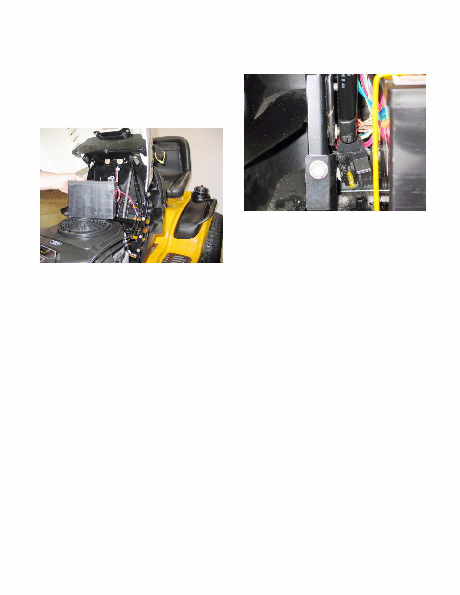
4.1. Remove the battery: See Figure 4.1.
• Disconnect the negative battery cable (black)
first, using a 7/16” wrench.
• Disconnect the positive battery cable (red) using
a 7/16” wrench.
• Remove the battery hold-down.
• Lift the battery from the tractor.
4.2. Disconnect the headlight harness. (Plug secured
to the hood lift cylinder).
4.3. Support the hood with an improvised prop-rod to
prevent damage.
4.4. Remove screws holding hinge support bar to
dash support using a 1/2” wrench.
4.5. Disconnect and remove the hood lift cylinders
using a small straight-blade screwdriver.
4.6. Remove screws & flat washers holding hinge
support bar to dash panel using a 3/8” wrench.
4.7. Lift hood and hinge assembly off of the tractor,
and remove it to a safe place.
4.8. Hood installation notes: See Figure 4.8.
• Position the hinge support bar over the two
spacers that partially cover the threads of the
balls that the that hood support struts attach to.
The slots in the ends of the bar will fit over the
spacers.
• Support the hood with an improvised prop rod.
• Install the screws that hold the hinge support bar
to the dash support and instrument panel.
• Snap the hood support cylinder into place, and
remove the prop rod.
• The remainder of the installation process is sim-
ply the reversal of the removal steps.
Figure 4.1
Figure 4.8
You're Reading a Preview
What's Included?
Fast Download Speeds
Online & Offline Access
Access PDF Contents & Bookmarks
Full Search Facility
Print one or all pages of your manual
$41.99
Cub Cadet 1525 Riding Mowers Complete Workshop Service Repair Manual
Viewed 16 Times Today

What's Included?
Fast Download Speeds
Online & Offline Access
Access PDF Contents & Bookmarks
Full Search Facility
Print one or all pages of your manual
$41.99

Secure transaction
What's Included?
Fast Download Speeds
Online & Offline Access
Access PDF Contents & Bookmarks
Full Search Facility
Print one or all pages of your manual
Description
Thank you for considering the Complete Workshop Service Repair Manual for Cub Cadet 1525 Riding Mowers.
This comprehensive manual covers every service and repair procedure necessary, making it an invaluable resource for both professional mechanics and DIY enthusiasts.
Description:
- Save money by performing your own repairs with easy-to-follow, step-by-step instructions and detailed pictures covering all areas of servicing and repairs.
- Once downloaded, the manual is yours to keep forever. You can print individual pages, chapters, or the entire manual, and it can also be saved to your tablet or smartphone.
Models Covered:
- All models, engines, trim, and transmission types are included.
Contents:
- This high-quality manual covers all repair procedures from A to Z, ensuring that every repair and service procedure is thoroughly explained.
Computer Requirements:
- This downloadable manual is compatible with all PC and MAC computers, tablets, and mobile phones. The only software required is Adobe Reader, which is typically pre-installed on most computers or can be downloaded for free.
Delivery:
- Upon payment via Visa, MasterCard, or PayPal, the manual will be instantly emailed to the address provided during checkout.
Customer satisfaction is guaranteed with this comprehensive workshop manual.


