

)
)
5000 SERIES
TRACTORS
SERVICE MANUAL
Form 553895 (4/85)

GROUP I. GENERAL
5000 SERIES
TRACTOR
Page 1-1 10/85
SERIAL NUMBER INFORMATION
TRACTOR
MODEL/SERIAL
NUMBER
FIGURE 1
SPECIFICATIONS
ENGINE
.Manufacturer
Model/Spec ..... .
Type ........... .
Bore and Stroke ...
Piston
Displacement .....
Mfr's H.P. Rating ..
Air Cleaner ...... .
Oil Capacity ..... .
Governor ........ .
Speed Control ... .
Starter .......... .
Charging System ..
Spark Plug Size .. .
Spark Plug ..... .
Spark Plug Gap .. .
Breaker Point Gap .
Timing ........... .
MODEL 5017G & 5017H
Kohler
KT 17 Spec. 24218, 24314 &
24351
Harz. shaft, air cooled
2 cyl., 4 cycle
3-1/8" (79 mm) x
2-3/4" (70 mm)
42.18 cu. ln. (690 cc)
17 H.P. at 3600 RPM
Paper Element Kohler 4508302
1.5 U.S. Qt. (1.4 liter)
Mechanical
Remote, cable operated
Bendix Type
15 Amp. flywheel Alternator
14 mm
Champion RV15YC
.025 (0.63 mm)
.020 (0.5 mm)
SP Mark in Timing Hole
ENGINE MODEL5018H
Manufacturer ....... • ..... Kohler
Model/Spec ............... M18QS Spec. 24512
Type ..................... Harz. shaft, air cooled 2 cyl.,
4 cycle
Bore and Stroke ........... 3-1/8" (79 mm) x
2-3/4" (70 mm)
Piston
Displacement ............. 42.18 cu. ln. (690 cc)
Mfr's H.P. Rating • ......... 18 H.P. at 3600 RPM
Air Cleaner ...... • ........ Paper Element 4508302
Oil Capacity .............. 1.5 U.S. Qt. (1.41iter)
Governor ................. Mechanical
Speed Control ............ Remote, cable operated
Starter .................... Bendix Type
Charging System .......... 15 Amp. flywheel Alternator
Spark Plug Size ........... 14 mm
Spark Plug ............... Champion RV15YC
Spark Plug Cap ............ 035 (0.89 mm)
5000 SERIES
TRACTOR
Page 1-2 10/85
GENERAl (Continued)
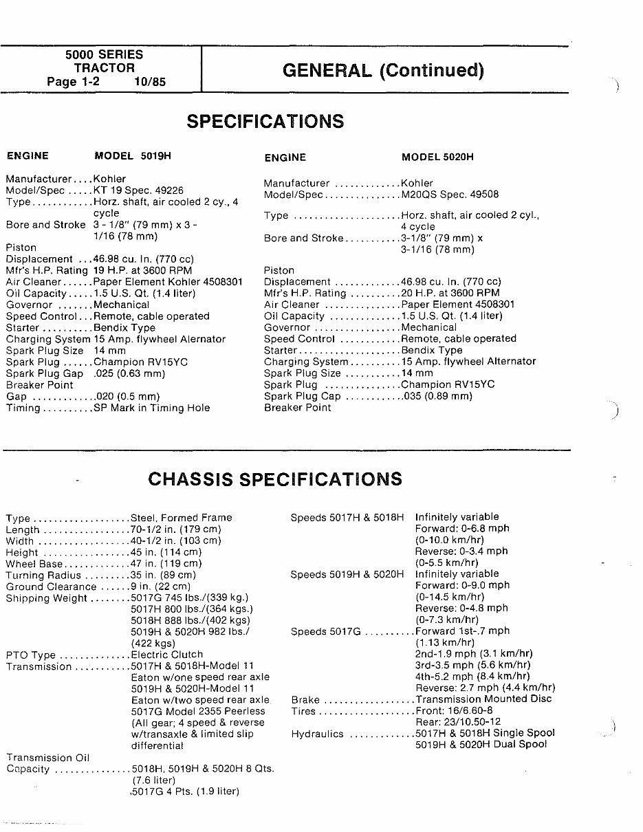
SPECIFICATIONS
ENGINE MODEL 5019H
Manufacturer .... Kohler
Model/Spec ..... KT 19 Spec. 49226
Type ............ Harz. shaft, air cooled 2 cy., 4
cycle
Bore and Stroke 3- 1/8" (79 mm) x 3-
1/16 (78 mm)
Piston
Displacement .. .46.98 cu. In. (770 cc)
Mfr's H.P. Rating 19 H.P. at 3600 RPM
A1r Cleaner ...... Paper Element Kohler 4508301
Oil Capacity ..... 1.5 U.S. Qt. (1.4 liter)
Governor ....... Mechanical
Speed Control ... Remote, cable operated
Starter .......... Bendix Type
Charging System 15 Amp. flywheel Alernator
Spark Plug Size 14 mm
Spark Plug ...... Champion RV15YC
Spark Plug Gap .025 (0.63 mm)
Breaker Point
Gap ............. 020 (0.5 mm)
Timing .......... SP Mark in Timing Hole
ENGINE MODEL 5020H
Manufacturer ............. Kohler
Model/Spec ............... M20QS Spec. 49508
Type ..................... Harz. shaft, air cooled 2 cyl.,
4 cycle
Bore and Stroke ........... 3-1/8" (79 mm) x
3-1/16 (78 mm)
Piston
Displacement ............. 46.98 cu. ln. (770 cc)
Mfr's H.P. Rating .......... 20 H.P. at 3600 RPM
Air Cleaner ............... Paper Element 4508301
Oil Capacity .............. 1.5 U.S. Qt. (1.4 liter)
Governor ................. Mechanical
Speed Control ............ Remote, cable operated
Starter .................... Bendix Type
Charging System .......... 15 Amp. flywheel Alternator
Spark Plug Size ........... 14 mm
Spark Plug ............... Champion RV15YC
Spark Plug Cap ............ 035 (0.89 mm)
Breaker Point
CHASSIS SPECIFICATIONS
Type ................... Steel. Formed Frame
Length ................. 70-1/2 in. (179 em)
Width .................. 40-1/2 in. (103 em)
Height ................ .45 in. (114 em)
Wheel Base ............ .47 in. (119 em)
Turning Radius ......... 35 in. (89 em)
Ground Clearance ...... 9 in. (22 em)
Shipping Weight ........ 5017G 7451bs./(339 kg.)
5017H 800 lbs./(364 kgs.)
5018H 888 lbs./(402 kgs)
5019H & 5020H 982 lbs./
(422kgs)
PTO Type .............. Electric Clutch
Transmission ........... 5017H & 5018H-Model 11
Eaton w/one speed rear axle
5019H & 5020H-Model 11
Eaton w/two speed rear axle
5017G Model 2355 Peerless
(All gear; 4 speed & reverse
w/transaxle & limited slip
differential
Transmission Oil
Capacity ............... 5018H, 5019H & 5020H 8 Qts.
(7.6 liter)
.5017G 4 Pis. (1.91iter)
Speeds 5017H & 5018H Infinitely variable
Forward: 0-6.8 mph
(0-10.0 km/hr)
Reverse: 0-3.4 mph
(0-5.5 km/hr)
Speeds 5019H & 5020H Infinitely variable
Forward: 0-9.0 mph
(0-14.5 km/hr)
Reverse: 0-4.8 mph
(0-7.3 km/hr)
Speeds 5017G .......... Forward 1st-.7 mph
(1.13 km/hr)
2nd-1.9 mph (3.1 km/hr)
3rd-3.5 mph (5.6 km/hr)
4th-5.2 mph (8.4 km/hr)
Reverse: 2.7 mph (4.4 km/hr)
Brake .................. Transmission Mounted Disc
Tires ................... Front: 16/6.60-8
Rear: 23/10.50-12
Hydraulics ............. 5017H & 5018H Single Spool
5019H & 5020H Dual Spool
)
GENERAL (Continued)
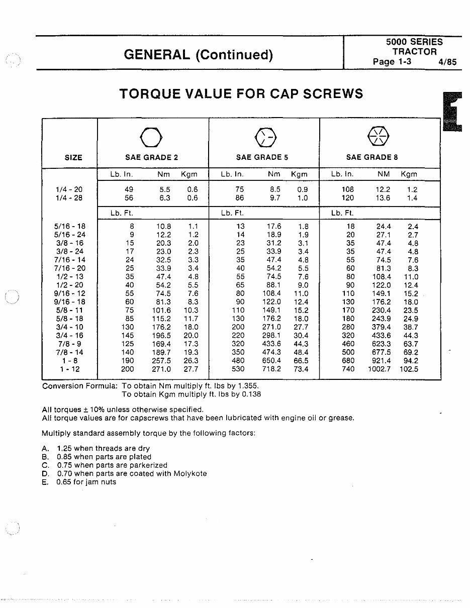
TORQUE VALUE FOR CAP SCREWS
0 G
5000 SERIES
TRACTOR
Page 1-3 4/85
[
@
\
SIZE SAE GRADE 2 SAE GRADE 5 SAE GRADE 8
Lb. ln. Nm Kgm Lb. ln. Nm Kgm Lb. ln. NM Kgm
1/4- 20 49 5.5 0.6 75 8.5 0.9 108 12.2 1.2
1/4- 28 56 6.3 0.6 86 9.7 1.0 120 13.6 1.4
Lb. Ft. Lb. Ft. Lb. Ft.
5/16- 18 8 10.8 1.1 13 17.6 1.8 18 24.4 2.4
5/16- 24 9 12.2 1.2 14 18.9 1.9 20 27.1 2.7
3/8- 16 15 20.3 2.0 23 31.2 3.1 35 47.4 4.8
3/8-24 17 23.0 2.3 25 33.9 3.4 35 47.4 4.8
7/16- 14 24 32.5 3.3 35 47.4 4.8 55 74.5 7.6
7/16-20 25 33.9 3.4 40 54.2 5.5 60 81.3 8.3
1/2- 13 35 47.4 4.8 55 74.5 7.6 80 108.4 11.0
1/2- 20 40 54.2 5.5 65 88.1 9.0 90 122.0 12.4
9/16- 12 55 74.5 7.6 80 108.4 11.0 110 149.1 15.2
9/16-18 60 81.3 8.3 90 122.0 12.4 130 176.2 18.0
5/8-11 75 101.6 10.3 110 149.1 15.2 170 230.4 23.5
5/8- 18 85 115.2 11.7 130 176.2 18.0 180 243.9 24.9
3/4- 10 130 176.2 18.0 200 271.0 27.7 280 379.4 38.7
3/4- 16 145 196.5 20.0 220 298.1 30.4 320 433.6 44.3
7/8-9 125 169.4 17.3 320 433.6 44.3 460 623.3 63.7
7/8- 14 140 189.7 19.3 350 474.3 48.4 500 677.5 69.2
1 - 8 190 257.5 26.3 480 650.4 66.5 680 921.4 94.2
1 - 12 200 271.0 27.7 530 718.2 73.4 740 1002.7 102.5
Conversion Formula: To obtain Nm multiply ft. lbs by 1.355.
To obtain Kgm multiply ft. lbs by 0.138
All torques± 10% unless otherwise specified.
All torque values are for capscrews that have been lubricated with engine oil or grease.
Multiply standard assembly torque by the following factors:
A. 1.25 when threads are dry
B. 0.85 when parts are plated
C. 0.75 when parts are parkerized
D. 0.70 when parts are coated with Molykote
E. 0.65 for jam nuts
5000 SERIES
TRACTOR
'age 1-4 4/85
GENERAl (Continued)
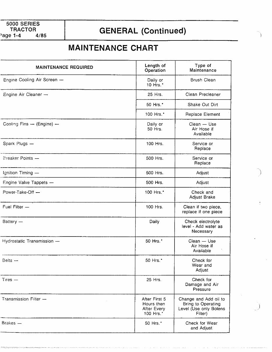
MAINTENANCE CHART
MAINTENANCE REQUIRED
Length of Type of
Operation Maintenance
Engme Cooling Air Screen - Daily or Brush Clean
10 Hrs. •
Engine Air Cleaner - 25 Hrs. Clean Precleaner
50 Hrs. • Shake Out Dirt
100 Hrs. • Replace Element
Fins - (Engine) - Daily or Clean- Use
50 Hrs. Air Hose if
Available
Spark Plugs - 100 Hrs. Service or
Replace
-·--
Preaker Points - 500 Hrs. Service or
Replace
lgnit1on Timing - 500 Hrs . Adjust
..
F.ngine Valve Tappets - 500 Hrs. Adjust
-
Power-Take-Off - 100 Hrs. • Check and
Adjust Brake
.
Fuel Filter - 100 Hrs. Clean if two piece,
replace if one piece
Battery- Daily Check electrolyte
level - Add water as
Necessary
Hydrostatic Transmission - 50 Hrs. • Clean- Use
Air Hose if
Available
Belts- 50 Hrs. • Check for
Wear and
Adjust
T1res- 25 Hrs. Check for
Damage and Air
Pressure
Transmission Filter - After First 5 Change and Add oil to
Hours then Bring to Operating
After Every Level (Use only Bolens
100 Hrs. • Filter)
-----
Brakes- 50 Hrs. • Check for Wear
and Adjust
-
)
)
)
GENERAL (Continued)
5000 SERIES
TRACTOR
Page 1-5 4/85
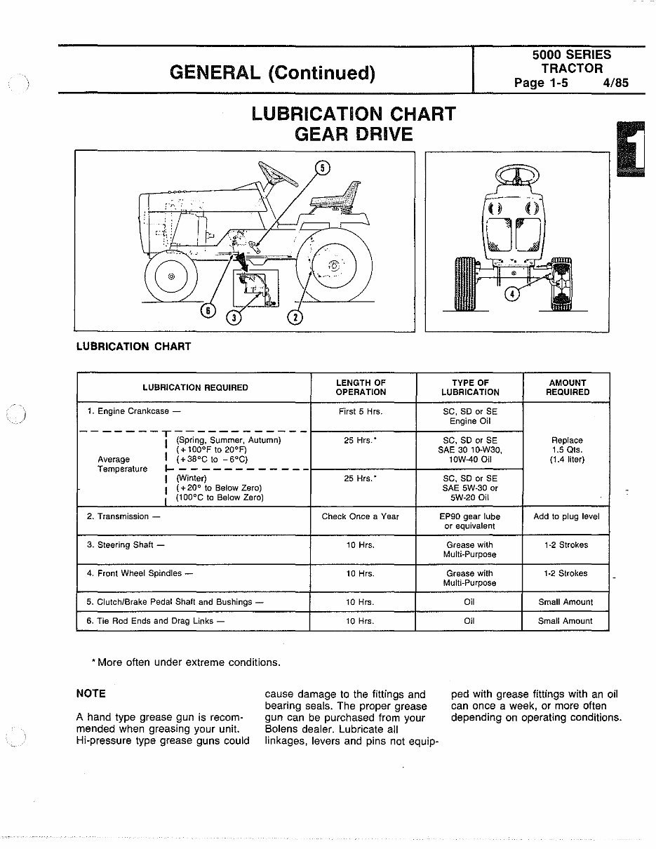
LUBRICATION CHART
GEAR DRIVE
(
0 0
00
LUBRICATION CHART
LUBRICATION REQUIRED
LENGTH OF TYPE OF AMOUNT
OPERATION LUBRICATION REQUIRED
1. Engine Crankcase - First 5 Hrs. SC, SD or SE
Engine Oil
-------T------------
25 Hrs. • SC, SD or SE Replace 1 (Spring, Summer, Autumn)
( + 100°F to 20°F) SAE 30 1 O-W30, 1.5 Ots.
Average I ( + 38°C to - 6°C)
Temperature
1-------------
I
(Winter) 25 Hrs. •
I
( + 20° to Below Zero)
I
(1 OO'C to Below Zero)
2. Transmission - Check Once a Year
3. Steering Shaft - 10 Hrs.
4. Front Wheel Spindles - 10 Hrs.
5. Clutch/Brake Pedal Shaft and Bushings - 10 Hrs.
6. Tie Rod Ends and Drag Links - 10 Hrs.
• More often under extreme conditions.
NOTE
A hand type grease gun is recom-
mended when greasing your unit.
Hi-pressure type grease guns could
cause damage to the fittings and
bearing seals. The proper grease
gun can be purchased from your
Bolens dealer. Lubricate all
linkages, levers and pins not equip-
10W-40 Oil (1.4 liter)
SC, SD or SE
SAE SW-30 or
SW-20 Oil
EP90 gear lube Add to plug level
or equivalent
Grease with 1·2 Strokes
Multi-Purpose
Grease with 1-2 Strokes
Multi-Purpose
Oil Small Amount
Oil Small Amount
ped with grease fittings with an oil
can once a week, or more often
depending on operating conditions.
5000 SERIES
TRACTOR
Page 1-6 4/85
GENERAL (Continued)
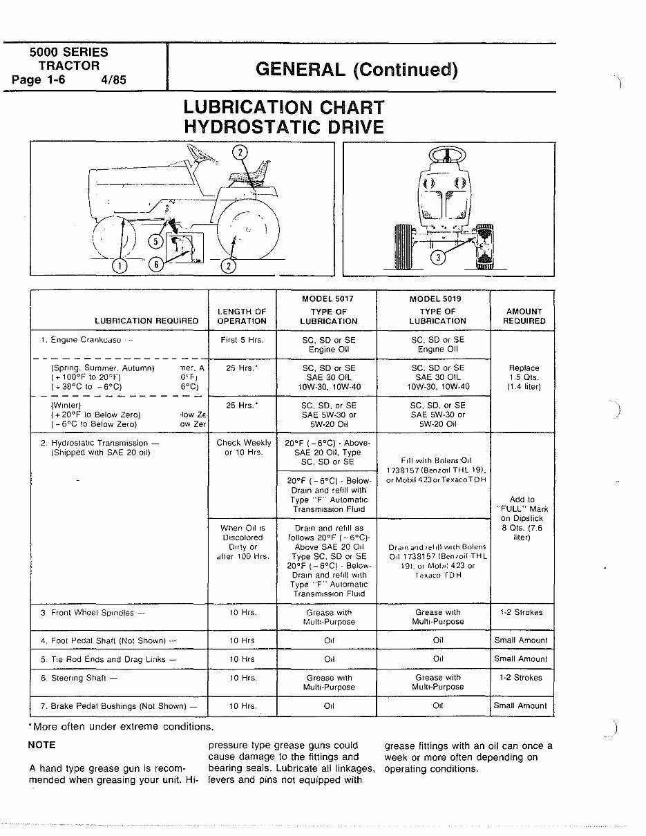
LUBRICATION CHART
HYDROSTATIC DRIVE
':\:::.,__ 2
---" ,, I"
. t
y
_,.:-- •,
1 2
MODEL 5017
LENGTH OF TYPE OF
LUBRICATION REQUIRED OPERATION LUBRICATION
1 _ Eng me Crankcdse F1rst 5 Hrs. SC, SD or SE
Engine Oil
-----------------
(Spnng. Summer. Autumn) A 25 Hrs. • SC, SD or SE
( + 100°F to 20°F) 0' F· 1 SAE 30 OIL
( + 38°C to - 6°C)
soC)
10W-30, 10W-40
1------------- ---
(Winter) 25 Hrs. • SC, SD, orSE
( + 20°F to Below Zero) ·low Ze SAE SW-30 or
(- 6°C to Below Zero) ow Zer SW-20 Oil
2 Hydrosta\lc Transm1ssion - Check Weekly 20°F (- 6°C) .
(Shipped With SAE 20 Oil) or 10 Hrs. SAE 20 Oil, Type
SC, SD or SE
- 20°F {- 6°C) - Below-
Dra1n and rehll w1th
Type "F" Automatic
Transm1sston FlUid
When OlliS Dram and ref11l as
DISCOlOred follows 20"F (- 6"C)-
I
D1rty or Above SAE 20 Od
dlter 100 Type SC. SD 01 SE
I
20"F (- 6"C) - Below-
Dra1n and refill w1th
Type "F'' Automahc
TransmiSSIOn Fluid
---
3 Front Wheel Sp1ndles - 10 Hrs. Grease wtth
Multi-Purpose
4. Foot Pedal Shaft (Not Shown) - 10 Hrs 011
5. T1e Rod Ends and Drag Lmks - 10 Hrs Oil
6. Steenng Shaft - 10 Hrs. Grease w1th
Multi-Purpose
7. Brake Pedal Bushings (Not Shown)- 10 Hrs. 011
• More often under extreme conditions_
NOTE
A hand type grease gun is recom-
mended when greasing your unit Hi-
pressure type grease guns could
cause damage to the fittings and
bearing seals. Lubricate all linkages,
levers and pins not equipped with
((I))
--
0 0
JO
. " !' _l"'· ..
MODEL 5019
TYPE OF AMOUNT
LUBRICATION REQUIRED
SC, SD or SE
Engme 01!
SC. SD or SE Replace
SAE 30 OIL 1.5 Ots.
1OW-30, 1OW-40 (1.4 liter)
SC. SD, or SE
SAE SW-30 or
SW-20 01l
Fill with Bolens-Qd
1738157 I Benzol! THL 19),
or Mobil 4 23 or Texaco TO H
Add to
"FULL" Mark
on D1pstick
8 Ols. (7.6
liter)
Dra1n and refill w11h Bolens
01l 1738157 IBen10il THL
19!, ur Mob•: 423 or
Texdt.:o TOH
Grease wHh 1-2 Strokes
Mult1-Purpose
011 Small Amount
Oil Small Amount
Grease with 1-2 Strokes
Mult1-Purpose
Oil Small Amount
grease fittings with an oil can once a
week or more often depending on
operating conditions-
)
)
.
GROUP II. ELECTRICAL SYSTEM
5000 SERIES
TRACTOR
Page 2-1 4/85
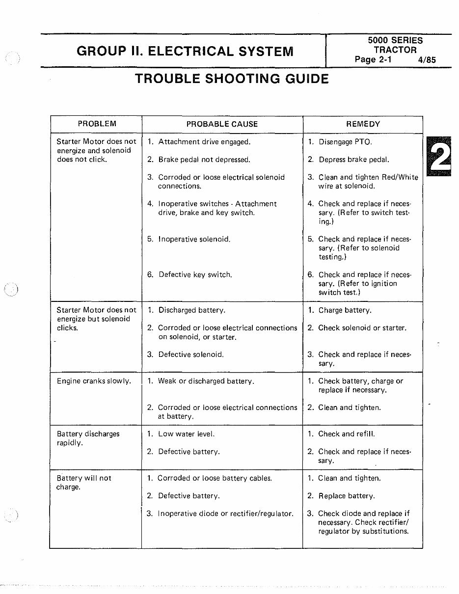
TROUBLE SHOOTING GUIDE
PROBLEM PROBABLE CAUSE REMEDY
Starter Motor does not 1. Attachment drive engaged. 1. Disengage PTO.
energize and solenoid
does not click. 2. Brake pedal not depressed. 2. Depress brake pedal.
3. Corroded or loose electrical solenoid 3. Clean and tighten Red/White
connections. wire at solenoid.
4. Inoperative switches· Attachment 4. Check and replace if neces·
drive, brake and key switch. sary. (Refer to switch test-
ing.)
5. Inoperative solenoid. 5. Check and replace if neces-
sary. (Refer to solenoid
testing.)
6. Defective key switch. 6. Check and replace if neces-
sary. (Refer to ignition
switch test.)
Starter Motor does not 1. Discharged battery. 1. Charge battery.
energize but solenoid
clicks. 2. Corroded or loose electrical connections 2. Check solenoid or starter.
on solenoid, or starter .
3. Defective solenoid. 3. Check and replace if neces-
sary.
Engine cranks slowly. 1. Weak or discharged battery. 1. Check battery, charge or
replace if necessary.
2. Corroded or loose electrical connections 2. Clean and tighten.
at battery.
Battery discharges 1. Low water level. 1. Check and refill.
rapidly.
2. Defective battery. 2. Check and replace if neces-
sary.
Battery will not 1. Corroded or loose battery cables. 1. Clean and tighten.
charge.
2. Defective battery. 2. Replace battery.
3. Inoperative diode or rectifier/regu Ia tor. 3. Check diode and replace if
necessary. Check rectifier/
regulator by substitutions.
5000 SERIES
TRACTOR
Page 2-2 4/85
PROBLEM
Lights not operating.
Attachment drive
inoperative (Attach-
ment drive light
works).
Attachment drive
inoperative (Attach-
ment light inoper-
ative).
Engine kills when
Attachment drive
switch in turned on.
Continued operation
of attachments when
operator is not seated.
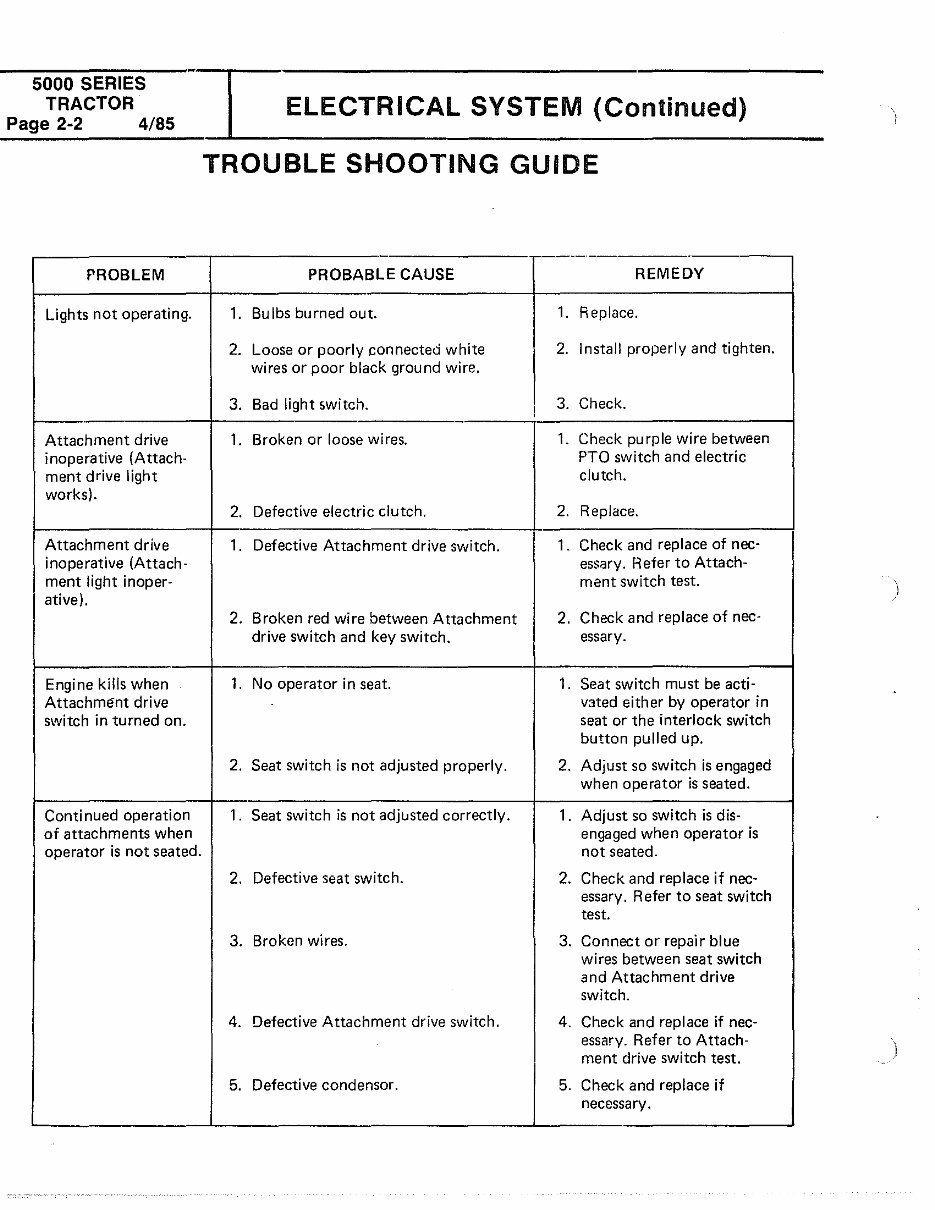
ElECTRICAl SYSTEM (Continued)
TROUBLE SHOOTING GUIDE
--
PROBABLE CAUSE REMEDY
1. Bulbs burned out. 1. Replace.
2. Loose or poorly connected white 2. Install properly and tighten.
wires or poor black ground wire.
3. Bad light switch. 3. Check.
'
1. Broken or loose wires. 1. Check purple wire between
PTO switch and electric
clutch.
2. Defective electric clutch. 2. Replace.
1 . Defective Attachment drive switch.
1 . Check and replace of nee-
essary. Refer to Attach-
ment switch test.
)
2. Broken red wire between Attachment 2.
Check and replace of nee-
drive switch and key switch. essary.
1. No operator in seat. 1 . Seat switch must be acti-
vated either by operator in
seat or the interlock switch
button pulled up.
2. Seat switch is not adjusted properly. 2. Adjust so switch is engaged
when operator is seated.
1 . Seat switch is not adjusted correctly. 1 . Adjust so switch is dis-
engaged when operator is
not seated.
2. Defective seat switch. 2. Check and replace if nee-
essary. Refer to seat switch
test.
3. Broken wires. 3. Connect or repair blue
wires between seat switch
and Attachment drive
switch.
4. Defective Attachment drive switch. 4. Check and replace if nee-
essary. Refer to Attach-
ment drive switch test.
5. Defective condenser. 5. Check and replace if
necessary.
ELECTRICAL SYSTEM (Continued)
5000 SERIES
TRACTOR
Page 2-3 4/85
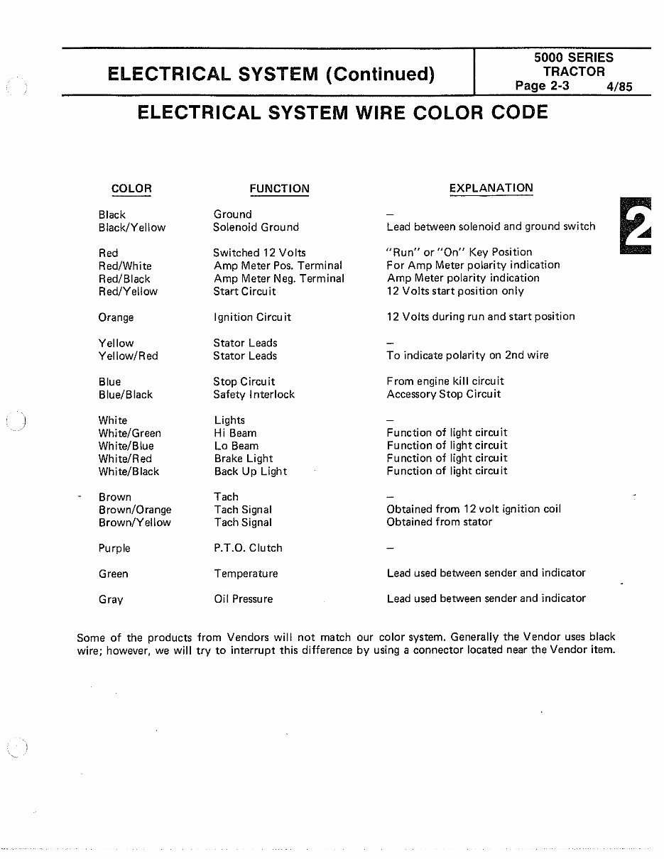
ELECTRICAL SYSTEM WIRE COLOR CODE
COLOR
Black
Black/Yellow
Red
Red/White
Red/Black
Red/Yellow
Orange
Yellow
Yellow/Red
Blue
Blue/Black
White
White/Green
White/Blue
White/Red
White/Black
Brown
Brown/Orange
Brown/Yell ow
Purple
Green
Gray
FUNCTION
Ground
Solenoid Ground
Switched 12 Volts
Amp Meter Pos. Terminal
Amp Meter Neg. Terminal
Start Circuit
Ignition Circuit
Stator Leads
Stator Leads
Stop Circuit
Safety Interlock
Lights
Hi Beam
Lo Beam
Brake Light
Back Up Light
Tach
Tach Signal
Tach Signal
P.T.O. Clutch
Temperature
Oil Pressure
EXPLANATION
Lead between solenoid and ground switch
"Run" or "On" Key Position
For Amp Meter polarity indication
Amp Meter polarity indication
12 Volts start position only
12 Volts during run and start position
To indicate polarity on 2nd wire
From engine kill circuit
Accessory Stop Circuit
Function of light circuit
Function of light circuit
Function of light circuit
Function of light circuit
Obtained from 12 volt ignition coil
Obtained from stator
Lead used between sender and indicator
Lead used between sender and indicator
Some of the products from Vendors will not match our color system. Generally the Vendor uses black
wire; however, we will try to interrupt this difference by using a connector located near the Vendor item.
You're Reading a Preview
What's Included?
Fast Download Speeds
Online & Offline Access
Access PDF Contents & Bookmarks
Full Search Facility
Print one or all pages of your manual
$35.99
Bolens 5000 series eliminator tractor service repair manual
Viewed 71 Times Today

What's Included?
Fast Download Speeds
Online & Offline Access
Access PDF Contents & Bookmarks
Full Search Facility
Print one or all pages of your manual
$35.99

Secure transaction
What's Included?
Fast Download Speeds
Online & Offline Access
Access PDF Contents & Bookmarks
Full Search Facility
Print one or all pages of your manual
Description
These digital manuals cover models built from 1983 through 1988, including the following models:
- 5017G
- 5017H
- 5018H
- 5019H
- 5020H


