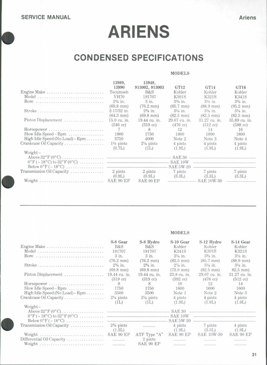
SERVICE MANUAL ARIENS Ariens CONDENSED SPECiFiCATiONS 13989, 13948, 13990 913002, 913003 Engine Make Tecumseh B&S Model VH70 191707 Bore 23/4 in. 3 in. (69.8 mm) (76.2 mm) Stroke 2-17/32 in. 2% in. (64.3 mm) (69.8 mm) Piston Displacement 15.0 cu. in. 19.44 cu. in. (246 cc) (319 cc) Horsepower 7 8 Slow Idle Speed-Rpm 1800 1750 High Idle Speed (No Load) - Rpm 3750 4000 Crankcase Oil Capacity IV2 pints 2V4 pints (0.7L) (lL) Weight- Above 32°F (0°C) 0°F(-18°C)to32°F(0°C) Below 0°F(-18''C) Transmission Oil Capacity 2 pints 2 pints (0.9L) (0.9L) Weight SAE 90 EP SAE 90 EP MODELS GT12 Kohler K301S 3% in. (85.7 mm) 31/4 in. (82.5 mm) 29.07 cu. in. (476 cc) 12 1800 Note 2 4 pints (L9L) — SAE 30 - - SAE low SAE 5W 20 7 pints (3.3L) GT14 Kohler K321S 3V2 in, (88.9 mm) 31/4 in. (82.5 mm) 31.27 cu. in. (512 cc) 14 1800 Notes 4 pints (1.9L) 7 pints (3.3L) ^ SAE lOW-30 GT16 Kohler K341S 3% in. (95.2 mm) 3V4 in. (82.5 mm) 35.89 cu. in. (588 cc) 16 1800 Note 4 4 pints (1.9L) 7 pints (3.3L) MODELS S-8 Gear S-8 Hydro S-10 Gear S-12 Hydro S-14 Gear Engine Make B&S B&S Kohler Kohler Kohler Model 191707 191707 K241S K301S K321S Bore 3 in. 3 in. 3V4 in. 3% in. 3V2 in. (76.2 mm) (76.2 mm) (82.5 mm) (85.7 mm) (88.9 mm) Stroke 2% in. 2% in. 2V8 in. 3V4 in. 3V4 in. (69.8 mm) (69.8 mm) (73.0 mm) (82.5 mm) 82.5 mm) Piston Displacement 19.44 cu. in. 19.44 cu. in. 23.9 cu. in. 29.07 cu. in. 31.27 cu. in. (319 cc) (319 cc) (392 cc) (476 cc) (512 cc) Horsepower 8 8 10 12 14 Slow Idle Speed-Rpm 1750 1750 1600 1600 1600 High Idle Speed (No Load)- Rpm 3500 3500 Note 1 Note 2 Note 3 Crankcase Oil Capacity 2V4 pints 2V4 pints 4 pints 4 pints 4 pints (lL) (lL) (1.9L) (1.9L) (1.9L) W eight- Above 32°F (0°C) 0°F(-18°C)to32 Below 0°F(-18°C) Transmission Oil Capacity 2% pints (L3L) Weight SAE 90 EP ATF Type "A" Differential Oil Capacity 2 pints Weight SAE 90 EP _ SAE 30 - - SAE low - SAE 5W-20 4 pints (1.9L) SAE 90 EP 7 pints (3.3L) SAE lOW-30 4 pints (1.9L) SAE 90 EP 31
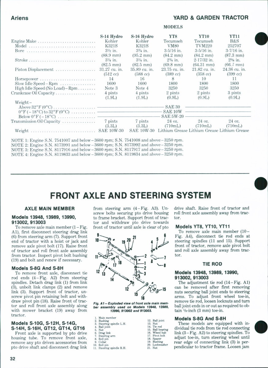
Ariens YARD & GARDEN TRACTOR MODELS S-14 Hydro S-16 Hydro YT8 YTIO YTll Engine Make Kohler Kohler Tecumseh Tecumseh B&S Model K321S K321S VM80 TVM220 252707 Bore 3V2 in. 33/4 in. 3-5/16 in. 3-5/16 in. 3-7/16 in. (88-9 mm) (95.2 mm) (84.2 mm) (84.2 mm) (87.3 mm) Stroke 3V4 in. 3V4 in. 2% in. 2-17/32 in. 2V8 in. (82.5 mm) (82.5 mm) (69.8 mm) (64.31mm) (66./mm) Piston Displacement 31.27 cu. in. 35.89 cu. in. 23.75 cu. in. 21.82 cu. in. 24.36 cu. in. (512 cc) (588 cc) (389 cc) (358 cc) (399 cc) Horsepower 14 16 8 10 11 Slow Idle Speed-Rpm 1600 1600 1800 1800 1800 High Idle Speed (No Load) - Rpm Note 3 Note 4 3250 3250 3250 Crankcase Oil Capacity 4 pints 4 pints 2 pints 2 pints 3 pints (1.9L) (1.9L) (0.9L) (0.9L) (0.9L) Weight- Above 32°F(0°C) SAE 30 — 0°F(-18°C)to32°F(0°C) SAE lOW Below0°F(-18°C) SAE 5W-20 Transmission Oil Capacity 7 pints 7 pints 24 oz. 24 oz. 24 oz. (3.3L) (3.3L) (710mL) (710mL) (710mL) Weight SAE lOW-30 SAE lOW-30 Lithium Grease Lithium Grease Lithium Grease NOTE 1: Engine S.N. 7541007 and below-3600 rpm; S.N. 7541008 and above-3250 rpm. NOTE 2: Engine S.N. 8173991 and below-3600 rpm; S.N. 8173992 and above-3250 rpm. NOTE 3: Engine S.N. 8117916 and below-3600 rpm; S.N. 8117917 and above-3250 rpm. NOTE 4: Engine S.N. 8119833 and below-3600 rpm; S.N. 8119834 and above-3250 rpm. FRONT AXLE AND STEERING SYSTEM AXLE MAIN MEMBER Models 13948, 13989,13990, 913002,913003 To remove axle main member (1 - Fig. Al), first disconnect steering drag link (6) from steering arm (7). Support front end of tractor with a hoist or jack and remove axle pivot bolt (17). Raise front of tractor and roll front axle assembly from tractor. Inspect pivot bolt bushing (19) and bolt and renew if necessary. Models S-8G And S-8H To remove front axle, disconnect tie rod ends (4-Fig. A2) from steering spindles. Detach drag link (1) from link (3), unbolt link clamps (2) and remove link (3). Support front of tractor, un- screw pivot pin retaining bolt and with- draw pivot pin (18). Raise front of trac- tor and roll front axle assembly along with mower bracket (19) away from tractor. Models S-10G, S-12H, S-14Q, S-14H, S-16H, QT12, GT14, GT16 Front axle is supported by pto drive housing tube. To remove front axle, remove any pto driven accessories from pto drive shaft and disconnect drag link from steering arm (4-Fig. A3). Un- screw bolts securing pto drive housing to frame bracket. Support front of trac- tor and withdraw pto drive towards front of tractor until axle is clear of pto IS Ftg. Al- Expioded vtew of front axte main mam- ber assembiy used on Modets 1394$, 13989, 13990, 913002 and 913003. 1. Main member 2. Bushing 3. Steering spindle L.H. 4. Ball joint 5. Nut 6. Drag link 7. Steering arm 8. Roll pin 9. Collar 10. Roll pin 11. Steering spindle R.H. 12. Ball joint 13. Nut 14. Tie rod 15. Ball bearing 16. Wheel hub 17. Pivot bolt 18. Spacer 19. Bushing 20. Lockwasher 21. Nut drive shaft. Raise front of tractor and roll front axle assembly away from trac- tor. Models YT8,YT10,YT11 To remove axle main member (10- Fig. A4), disconnect tie rod ends at steering spindles (11 and 15). Support front of tractor, remove axle pivot bolt and roll axle assembly away from trac- tor. TIE ROD Models 13948, 13989, 13990, 913002,913003 The adjustment tie rod (14-Fig. Al) can be removed after first removing nuts securing ball joint ends to steering arms. To adjust front wheel toe-in, remove tie rod, loosen locknuts and turn ball joint ends in or out as required to ob- tain Vs-inch (3 mm) toe-in. Models S-8G And S-8H These models are equipped with in- dividual tie rods from tie rod connecting link (3-Fig. A2) to steering spindles. To adjust toe-in, turn steering wheel until rear edge of connecting link (3) is per- pendicular to tractor frame. Loosen jam 32
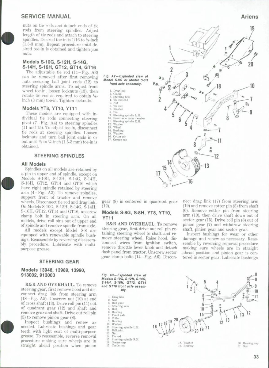
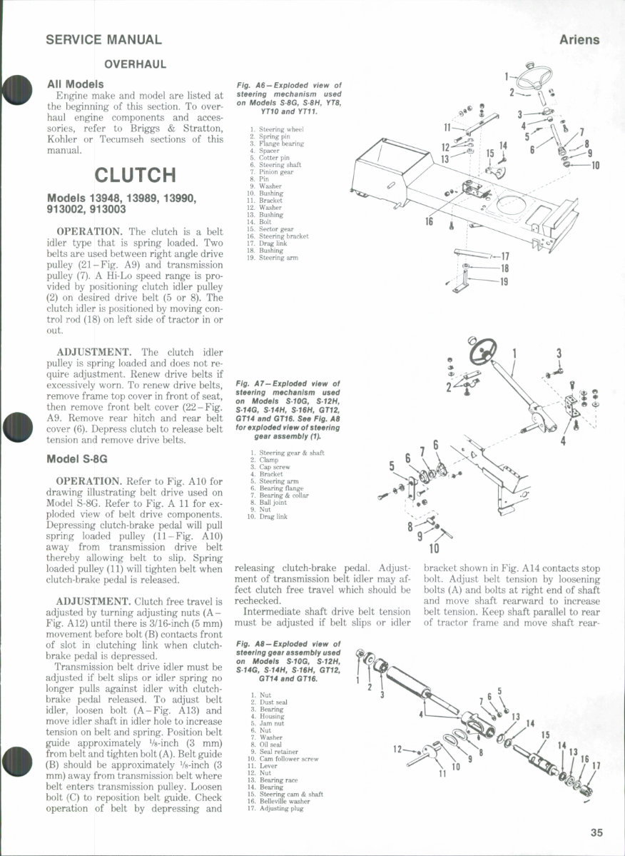
SERVICE MANUAL Ariens nuts on tie rods and detach ends of tie rods from steering spindles. Adjust len^,^h of tie rods and attach to steering spindles. Desired toe-in is 1/16 to Vs-inch (L5-3 mm). Repeat procedure until de- sired toe-in is obtained and tighten jam nuts. Models S-10G, S-12H, S-14G, S-14H, S-16H, GT12, GT14, GT16 The adjustable tie rod (14-Fig. A3) can be removed after first removing nuts securing ball joint ends (12) to steering spindle arms. To adjust front wheel toe-in, loosen locknuts (13), then rotate tie rod as required to obtain Vs- inch (3 mm) toe-in. Tighten locknuts. Models YT8, YT10, YT11 These models are equipped with in- dividual tie rods connecting steering pivot (7-Fig. A4) to steering spindles (11 and 15). To adjust toe-in, disconnect tie rods at steering spindles. Loosen locknuts and turn ball joint ends in or out until Vs to V4-inch (1.5-3 mm) toe-in is obtained. STEERING SPINDLES All Models Spindles on all models are retained by a pin in upper end of spindle, except on Models S-lOG, S-12H, S-14G, S-14H, S-16H, GT12, GT14 and GT16 which have right spindle retained by steering arm (4-Fig. A3). To remove spindles, support front of tractor and remove wheels. Disconnect tie rod and drag link. On Models S-lOG, S-12H, S-14G, S-14H, S-16H, GT12, GT14 and GT16, unscrew clamp bolt in steering arm. On all models, drive roll pins out of upper end of spindle and remove spindle from axle. All models except Model S-8 are equipped with renewable spindle bush- ings,. Reassemble by reversing disassem- bly procedure. Lubricate with multi- purpose grease. STEERING GEAR Models 13948, 13989, 13990, 913002,913003 R&R AND OVERHAUL. To remove steering gear, first remove hood and dis- connect drag link from steering arm (18-Fig. A5). Unscrew nut (10) at end of cross shaft (13). Drive roll pin (11) out of quadrant gear (12) and shaft and remove gear and shaft. Drive out roll pin (5) to remove pinion gear (8). Inspect bushings and renew as needed. Lubricate bushings and gear teeth with light coat of multi-purpose grease. To reassemble, reverse removal procedure making sure wheels are in straight ahead position when pinion rig. > Mode> \2 — Expioded view of r SBG or Modei S8H front axie assembly. I. 2. 3. 4. 5. 6. 7. 8. 9. 10. 11. 12. 13. 14. 15. 16. 17. Drag link Glamp Steering link Tie rod end Nut Tie rod Washer Pin Steering spindle L.H. Front axle main member Steering spindle R.H. Washer Wheel Bushing Washer Getter pin Grease cap gear (8) is centered in quadrant gear (12). Models S 8G, S-8H, YT8, YT10, YT11 R&R AND OVERHAUL. To remove steering gear, first drive out roll pin re- taining steering wheel to shaft and re- move steering wheel. Raise hood, dis- connect wires from ignition switch, remove throttle lever knob and detach dash panel from tractor. Unscrew sector gear clamp bolts (14-Fig. A6). Discon- nect drag link (17) from steering arm (19) and remove cotter pin (5) from shaft (6). Remove cotter pin from steering arm (19), then drive shaft down out of sector gear (15). Drive roll pin (8) out of pinion gear (7) and withdraw steering shaft, pinion gear and sector gear. Inspect bushings for wear or other damage and renew as necessary. Reas- semble by reversing removal procedure making sure wheels are in straight ahead position and pinion gear is cen- tered in sector gear. Lubricate bushings Fig. A3—Expioded view of Modeis SrOG, S-T2H, S.T4G, S-14H, S16H, GT12, GTU and GT1B front axie assem- biy. 1. Drag link 2. Nut 3. Ball joint 4. Steering arm 5. Bolt 6. Bushing 7. Front axle 8. Collar 9. Bushing 10. Washer 11. Steering spindle L.H. 12. Ball joint 13. Nut 14. Tie rod 15. Steering spindle R.H. 16. Grease cap 17. Castle nut 14 '^ 20. Bearing cup 21. Seal 33
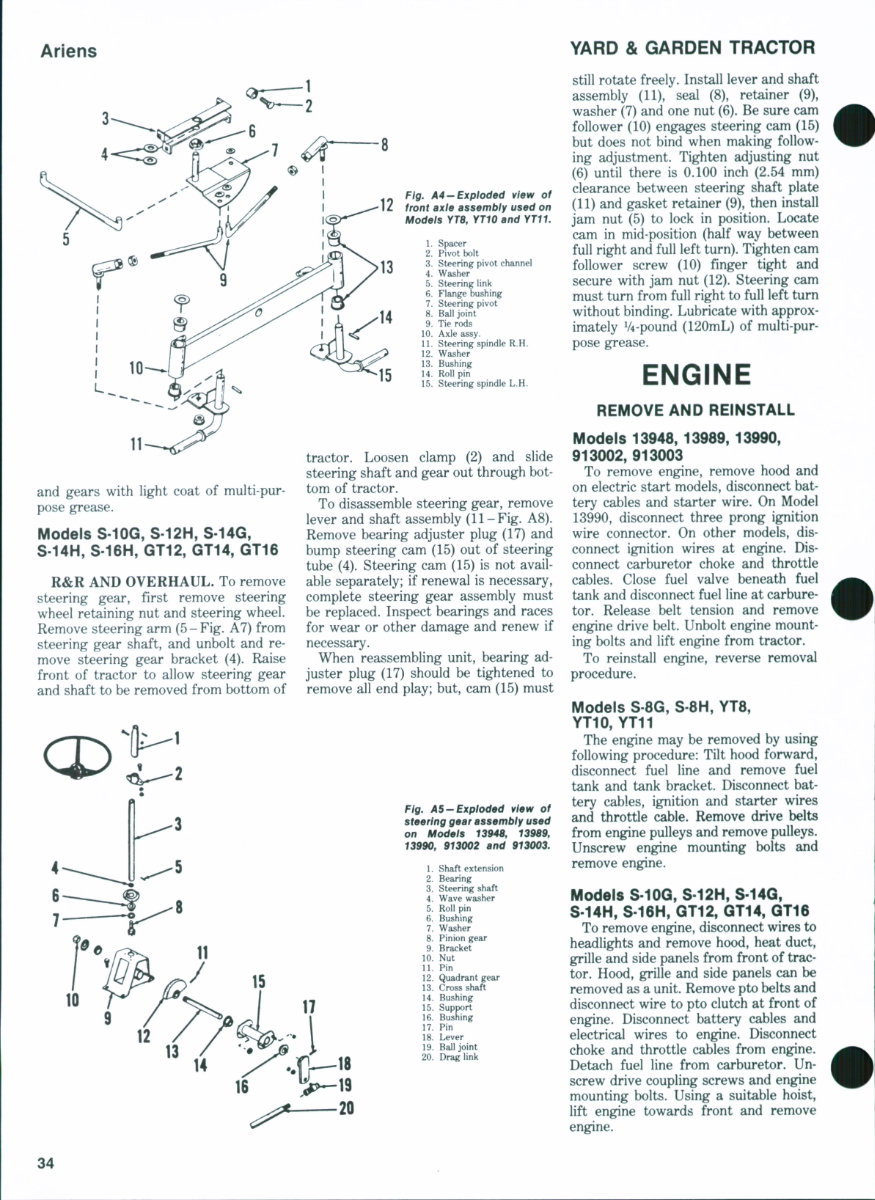
Ariens YARD & GARDEN TRACTOR 11 and gears with light coat of multi-pur- pose grease. Models S-10G, S-12H, S-14G, S-14H, S-16H, GT12, GT14, GT16 R&R AND OVERHAUL. To remove steering gear, first remove steering wheel retaining nut and steering wheel. Remove steering arm (5-Fig. A7) from steering gear shaft, and unbolt and re- move steering gear bracket (4). Raise front of tractor to allow steering gear and shaft to be removed from bottom of Ftg. A4-Exptoded view of 12 front axte assembty used on Modets YT8, YTIO and YT11. 1. Spacer 2. Pivot bolt 3. Steering pivot channel 4. Washer 5. Steering link 6. Flange bushing 7. Steering pivot 8. Ball joint 9. Tie rods 10. Axle assy. 11. Steering spindle R.H. 12. Washer 13. Bushing 14. Roll pin 15. Steering spindle L.H. tractor. Loosen clamp (2) and slide steering shaft and gear out through bot- tom of tractor. To disassemble steering gear, remove lever and shaft assembly (11-Fig. A8). Remove bearing adjuster plug (17) and bump steering cam (15) out of steering tube (4). Steering cam (15) is not avail- able separately; if renewal is necessary, complete steering gear assembly must be replaced. Inspect bearings and races for wear or other damage and renew if necessary. When reassembling unit, bearing ad- juster plug (17) should be tightened to remove all end play; but, cam (15) must Ftg. AS-Exploded vtaw of steertng gear assembty used on Modets 13948, 13989, 13990, 913002 and 913003. 1. Shaft extension 2. Bearing 3. Steering shaft 4. Wave washer 5. Roll pin 6. Bushing 7. Washer 8. Pinion gear 9. Bracket 10. Nut 11. Pin 12. Quadrant gear 13. Cross shaft 14. Bushing 15. Support 16. Bushing 17. Pin 18. Lever 19. Ball joint 20. Drag link still rotate freely. Install lever and shaft assembly (11), seal (8), retainer (9), washer (7) and one nut (6). Be sure cam follower (10) engages steering cam (15) but does not bind when making follow- ing adjustment. Tighten adjusting nut (6) until there is 0.100 inch (2.54 mm) clearance between steering shaft plate (11) and gasket retainer (9), then install jam nut (5) to lock in position. Locate cam in mid-position (half way between full right and full left turn). Tighten cam follower screw (10) finger tight and secure with jam nut (12). Steering cam must turn from full right to full left turn without binding. Lubricate with approx- imately V4-pound (120mL) of multi-pur- pose grease. ENGINE REMOVE AND REINSTALL Models 13948, 13989,13990, 913002,913003 To remove engine, remove hood and on electric start models, disconnect bat- tery cables and starter wire. On Model 13990, disconnect three prong ignition wire connector. On other models, dis- connect ignition wires at engine. Dis- connect carburetor choke and throttle cables. Close fuel valve beneath fuel tank and disconnect fuel line at carbure- tor. Release belt tension and remove engine drive belt. Unbolt engine mount- ing bolts and lift engine from tractor. To reinstall engine, reverse removal procedure. Models S 8G, S 8H, YT8, YT10, YT11 The engine may be removed by using following procedure: Tilt hood forward, disconnect fuel line and remove fuel tank and tank bracket. Disconnect bat- tery cables, ignition and starter wires and throttle cable. Remove drive belts from engine pulleys and remove pulleys. Unscrew engine mounting bolts and remove engine. Models S-10G, S-12H, S-14Q, S-14H, S-16H, GT12, GT14, GT18 To remove engine, disconnect wires to headlights and remove hood, heat duct, grille and side panels from front of trac- tor. Hood, grille and side panels can be removed as a unit. Remove pto belts and disconnect wire to pto clutch at front of engine. Disconnect battery cables and electrical wires to engine. Disconnect choke and throttle cables from engine. Detach fuel line from carburetor. Un- screw drive coupling screws and engine mounting bolts. Using a suitable hoist, lift engine towards front and remove engine. 34
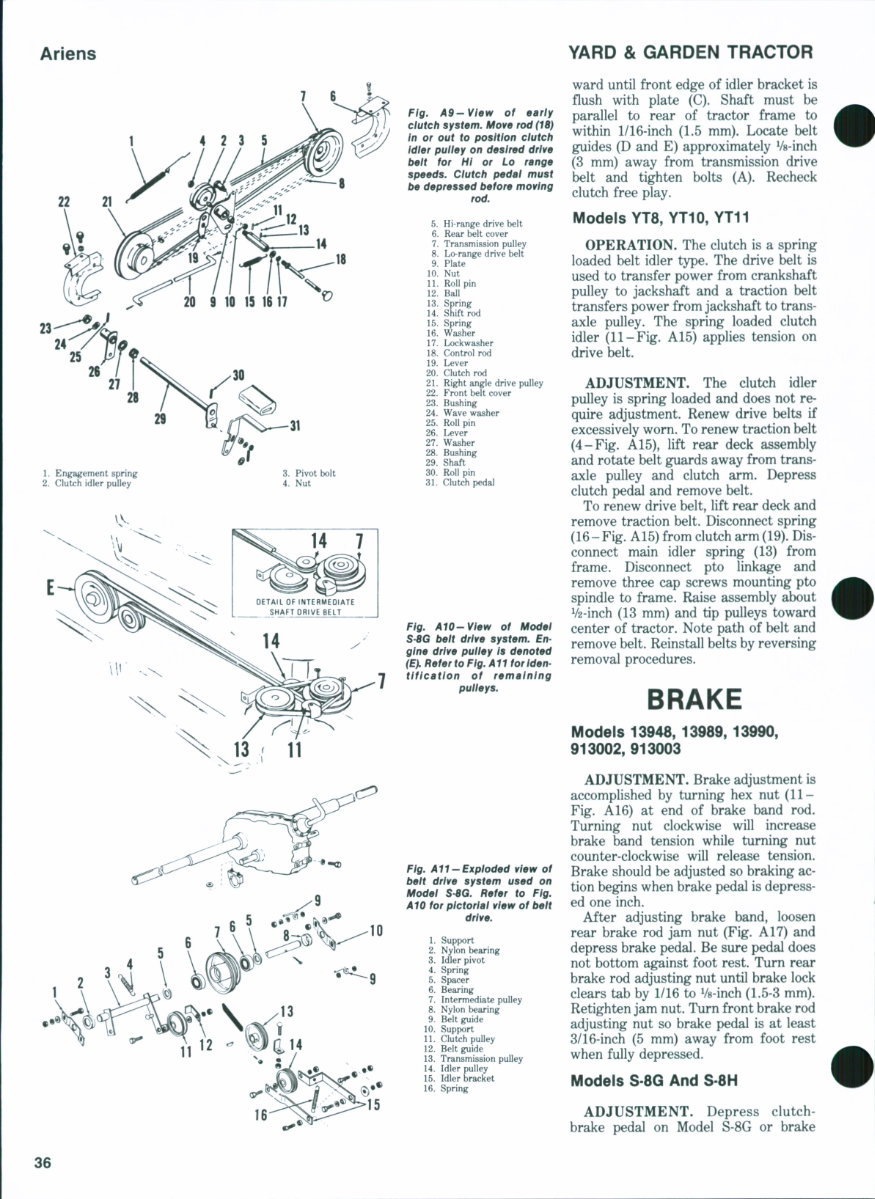
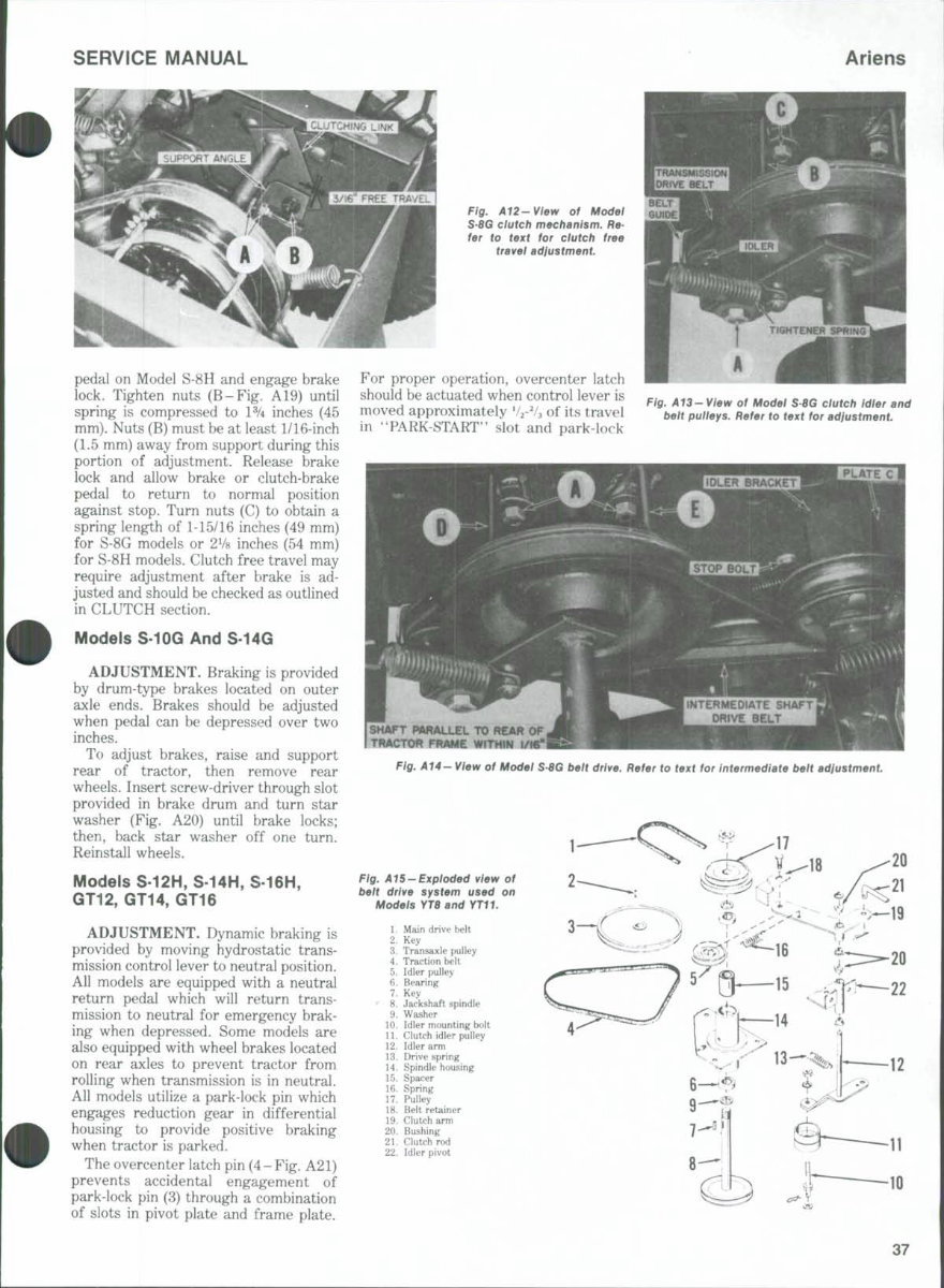
SERVICE MANUAL Ariens OVERHAUL Ail Models Engine make and model are listed at the beginning of this section. To over- haul engine components and acces- sories, refer to Briggs & Stratton, Kohler or Tecumseh sections of this manual. CLUTCH Models 13948, 13989, 13990, 913002,913003 OPERATION. The clutch is a belt idler type that is spring loaded. Two belts are used between right angle drive pulley (21-Fig. A9) and transmission pulley (7). A Hi-Lo speed range is pro- vided by positioning clutch idler pulley (2) on desired drive belt (5 or 8). The clutch idler is positioned by moving con- trol rod (18) on left side of tractor in or out. ADJUSTMENT. The clutch idler pulley is spring loaded and does not re- quire adjustment. Renew drive belts if excessively worn. To renew drive belts, remove frame top cover in front of seat, then remove front belt cover (22-Fig. A9. Remove rear hitch and rear belt cover (6). Depress clutch to release belt tension and remove drive belts. Model S 8G OPERATION. Refer to Fig. AlO for drawing illustrating belt drive used on Model S-8G. Refer to Fig. A 11 for ex- ploded view of belt drive components. Depressing clutch-brake pedal will pull spring loaded pulley (11-Fig. AlO) away from transmission drive belt thereby allowing belt to slip. Spring loaded pulley (11) will tighten belt when clutch-brake pedal is released. ADJUSTMENT. Clutch free travel is adjusted by turning adjusting nuts (A- Fig. A12) until there is 3/16-inch (5 mm) movement before bolt (B) contacts front of slot in clutching link when clutch- brake pedal is depressed. Transmission belt drive idler must be adjusted if belt slips or idler spring no longer pulls against idler v/ith clutch- brake pedal released. To adjust belt idler,, loosen bolt (A-Fig. A13) and move idler shaft in idler hole to increase tension on belt and spring. Position belt guide approximately Vs-inch (3 mm) from belt and tighten bolt (A). Belt guide (B) should be approximately Vs-inch (3 mm) away from transmission belt where belt enters transmission pulley. Loosen bolt (C) to reposition belt guide. Check operation of belt by depressing and Fig. A6 —Exploded view of steering mechanism used on Modeis S-8G, SSH, YT8, YTIOand YT11. 1. Steering wheel 2. Spring pin 3. Flange bearing 4. Spacer 5. Cotter pin 6. Steering shaft 7. Pinion gear 8. Pin 9. Washer 10. Bushing 11. Bracket 12. Washer 13. Bushing 14. Bolt 15. Sector gear 16. Steering bracket 17. Drag link 18. Bushing 19. Steering arm Fig. A7-Expioded view of steering mechanism used on Modeis S-10G, S12H, S-74G, S-14H, S16H, GT12, GT14 and GT16. See Fig. A8 for exploded view of steering gear assembiy (1). 1. Steering gear & shaft 2. Clamp 3. Cap screw 4. Bracket 5. Steering arm 6. Bearing flange 7. Bearing & collar 8. Ball joint 9. Nut 10. Drag link releasing clutch-brake pedal. Adjust- ment of transmission belt idler may af- fect clutch free travel which should be rechecked. Intermediate shaft drive belt tension must be adjusted if belt slips or idler Fig. AB — Expioded view of steering gear assembiy used on Modeis SfOG, 5T2H, S14G, S-14H, S-16H, GT12, GT14 and GT16. 1. Nut 2. Dust seal 3. Bearing 4. Housing 5. Jam nut 6. Nut 7. Washer 8. Oil seal 9. Seal retainer 10. Cam follower screw 11. Lever 12. Nut 13. Bearing race 14. Bearing 15. Steering cam & shaft 16. Belleville washer 17. Adjusting plug bracket shown in Fig. A14 contacts stop bolt. Adjust belt tension by loosening bolts (A) and bolts at right end of shaft and move shaft rearward to increase belt tension. Keep shaft parallel to rear of tractor frame and move shaft rear- 35
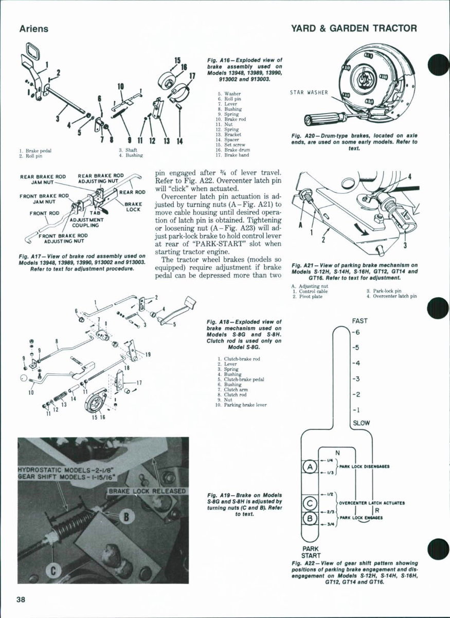
Ariens YARD & GARDEN TRACTOR 7 6 . Engagement spring 2. Clutch idler pulley Fig. A9-Vlew of early dutch system. Move rod (18} In or out to position clutch Idler pulley on desired drive beit for Hi or Lo range speeds, dutch pedai must be depressed before moving rod. 5. Hi-range drive belt 6. Rear belt cover 7. Transmission pulley 8. Lo-range drive belt 9. Plate 10. Nut 11. Roll pin 12. Ball 13. Spring 14. Shift rod 15. Spring 16. Washer 17. Lockwasher 18. Control rod 19. Lever 20. Clutch rod 21. Right angle drive pulley 22. Front belt cover 23. Bushing 24. Wave washer 25. Roll pin 26. Lever 27. Washer 28. Bushing 29. Shaft 30. Roll pin 31. Clutch pedal Fig. AiO-View of Model S-8G belt drive system. En- gine drive pulley Is denoted (E). Refer to Fig. All forlden- tlflcatlon of remaining pulleys. Fig. All-Exploded view of belt drive system used on Modei $-8G. Refer to Fig. A10 for pictorial view of belt drive. 1. Support 2. Nylon bearing 3. Idler pivot 4. Spring 5. Spacer 6. Bearing 7. Intermediate puHey 8. Nylon beting 9. Belt guide 10. Support 11. Clutch pulley 12. Belt guide 13. Transmission pulley 14. Idler pulley 15. Idler bracket 16. Spring ward until front edge of idler bracket is flush with plate (C). Shaft must be parallel to rear of tractor frame to within 1/16-inch (1.5 mm). Locate belt guides (D and E) approximately Vs-inch (3 mm) away from transmission drive belt and tighten bolts (A). Recheck clutch free play. Models YT8,YT10,YT11 OPERATION. The clutch is a spring loaded belt idler type. The drive belt is used to transfer power from crankshaft pulley to jackshaft and a traction belt transfers power from jackshaft to trans- axle pulley. The spring loaded clutch idler (11-Fig. A15) applies tension on drive belt. ADJUSTMENT. The clutch idler pulley is spring loaded and does not re- quire adjustment. Renew drive belts if excessively worn. To renew traction belt (4-Fig. A15), lift rear deck assembly and rotate belt guards away from trans- axle pulley and clutch arm. Depress clutch pedal and remove belt. To renew drive belt, lift rear deck and remove traction belt. Disconnect spring (16-Fig. A15) from clutch arm (19). Dis- connect main idler spring (13) from frame. Disconnect pto linkage and remove three cap screws mounting pto spindle to frame. Raise assembly about V2-inch (13 mm) and tip pulleys toward center of tractor. Note path of belt and remove belt. Reinstall belts by reversing removal procedures. BRAKE Models 13948,13989,13990, 913002, 913003 ADJUSTMENT. Brake adjustment is accomplished by turning hex nut (11- Fig. A16) at end of brake band rod. Turning nut clockwise will increase brake band tension while turning nut counter-clockwise will release tension. Brake should be adjusted so braking ac- tion begins when brake pedal is depress- ed one inch. After adjusting brake band, loosen rear brake rod jam nut (Fig. A17) and depress brake pedal. Be sure pedal does not bottom against foot rest. Turn rear brake rod adjusting nut until brake lock clears tab by 1/16 to Vs-inch (1.5-3 mm). Retighten jam nut. Turn front brake rod adjusting nut so brake pedal is at least 3/16-inch (5 mm) away from foot rest when fully depressed. Models S 8G And S 8H ADJUSTMENT. Depress clutch- brake pedal on Model S-8G or brake 36
SERVICE MANUAL Ariens Fig. A12-View of Modei S-8G ciutch mechanism. Re- fer to text for ciutch free travei adiustment pedal on Model S-8H and engage brake lock. Tighten nuts (B-Fig. A19) until spring is compressed to l^A inches (45 mm). Nuts (B) must be at least 1/16-inch (1.5 mm) away from support during this portion of adjustment. Release brake lock and allow brake or clutch-brake pedal to return to normal position against stop. Turn nuts (C) to obtain a spring length of 1-15/16 inches (49 mm) for S-8G models or 2V8 inches (54 mm) for S-8H models. Clutch free travel may require adjustment after brake is ad- justed and should be checked as outlined in CLUTCH section. Models S-10G And S-14G ADJUSTMENT. Braking is provided by drum-type brakes located on outer axle ends. Brakes should be adjusted when pedal can be depressed over two inches. To adjust brakes, raise and support rear of tractor, then remove rear wheels. Insert screw-driver through slot provided in brake drum and turn star washer (Fig. A20) until brake locks; then, back star washer off one turn. Reinstall wheels. Models S-12H, S-14H, S-16H, GT12, GT14, GT16 ADJUSTMENT. Dynamic braking is provided by moving hydrostatic trans- mission control lever to neutral position. All models are equipped with a neutral return pedal which will return trans- mission to neutral for emergency brak- ing when depressed. Some models are also equipped with wheel brakes located on rear axles to prevent tractor from rolling when transmission is in neutral. All models utilize a park-lock pin which engages reduction gear in differential housing to provide positive braking when tractor is parked. The overcenter latch pin (4-Fig. A21) prevents accidental engagement of park-lock pin (3) through a combination of slots in pivot plate and frame plate. For proper operation, overcenter latch should be actuated when control lever is moved approximately V2-V3 of its travel in ''PARK-START" slot and park-lock Fig, A13- View of Modei S8G clutch idier and beit puiieys. Refer to text for adfustment. SMAfT PARALLEL TO REAR Of 4 TI%ACTOR FRAME WITHIN ! Fig. 4 7 4 - Wew of Model S8G belt drive. Refer to text for intermediate belt adiustment Fig. A15-Expioded view of beit drive system used on Modeis YT8and YT11. 1. Main drive belt 2. Key 3. Transaxle pulley 4. Traction belt 5. Idler pulley 6. Bearing 7. Key 8. Jackshaft spindle 9. Washer 10. Idler mounting bolt 11. Clutch idler pulley 12. Idler arm 13. Drive spring 14. Spindle housing 15. Spacer 16. Spring 17. Pulley 18. Belt retainer 19. Clutch arm 20. Bushing 21. Clutch rod 22. Idler pivot 37
Ariens YARD & GARDEN TRACTOR 14 1. Brake pedal 2. Roll pin Fig. A16~Exploded view of brake assembiy used on Models 13948, 13989, 13990, 913002 and 913003. 5. Washer 6. Roll pin 7. Lever 8. Bushing 9. Spring 10. Brake rod 11. Nut 12. Spring 13. Bracket 14. Spacer 15. Set screw 16. Brake drum 17. Brakeband STAR WASHER Fig. A20—Drum-type brakes, located on axle ends, are used on some early models. Refer to text REAR BRAKE ROD JAM NUT FRONT BRAKE ROD JAM NUT REAR BRAKE ROD ADJUSTING N i n > REAR ROD \ BRAKE LOCK O BRAKE ROD ADJUSTING NUT Fig. A17- View of brake rod assembly used on Models 13948, 13989, 13990, 913002 and 913003. Refer to text for adiustment procedure. pin engaged after % of lever travel. Refer to Fig. A22. Overcenter latch pin will "click" when actuated. Overcenter latch pin actuation is ad- justed by turning nuts (A-Fig. A21) to move cable housing until desired opera- tion of latch pin is obtained. Tightening or loosening nut (A-Fig. A23) will ad- just park-lock brake to hold control lever at rear of "PARK-START" slot when starting tractor engine. The tractor wheel brakes (models so equipped) require adjustment if brake pedal can be depressed more than two 15 16 HYDROSTATIC MODELS-2-i/8** GEAR SHIFT MODELS- 1-15/16" LOCK RELEASED Fig. A18-Exploded view of brake mechanism used on Models S8G and S-8H. Clutch rod Is used oniy on Model S8G. 1. Clutch-brake rod 2. Lever 3. Spring 4. Bushing 5. Clutch-brake pedal 6. Bushing 7. Clutch arm 8. Clutch rod 9. Nut 10. Parking brake lever Fig. A19-Brake on Models S-8G and S-8H Is adjusted by turning nuts (C and Bji Refer to text. Fig. A21 - View of parking brake mechanism on Modeis $'12H, S'14H, S16H, GT12, GT14 and GT1$. Refer to text for adiustment. A. Adjusting nut 1. Control cable 2. Pivot plate 3. Park-lock pin 4. Overcenter latch pin MRK LOCK DItCMtAtCt > OVERCENTER LATCH ACTUATES PARK START Fig. A22—View of gear shift pattern showing positions of parking brake engagement and dis- engagement on Models S'12H, S'14H, S'18H, GT12, GT14 and GT16. 38
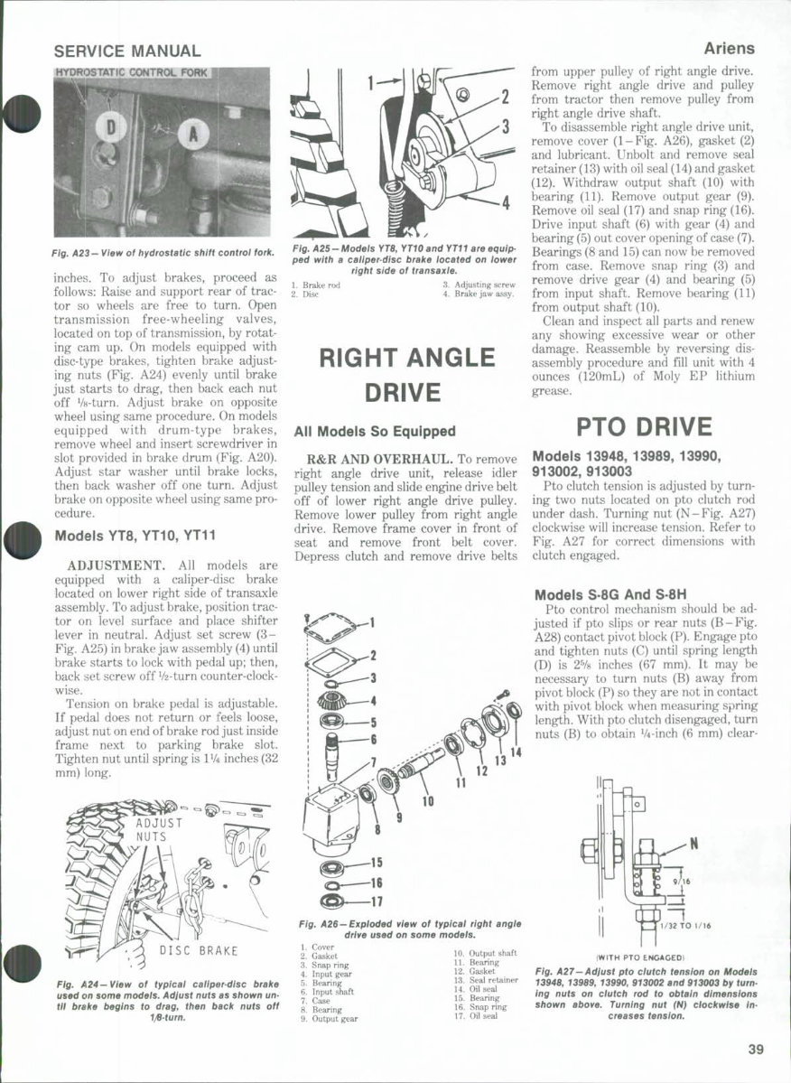
SERVICE MANUAL Fig. A23- View of hydrostatic shift control fork, inches. To adjust brakes, proceed as follows: Raise and support rear of trac- tor so wheels are free to turn. Open transmission free-wheeling valves, located on top of transmission, by rotat- ing cam up. On models equipped with disc-t^e brakes, tighten brake adjust- ing nuts (Fig. A24) evenly until brake just starts to drag, then back each nut off V8-turn. Adjust brake on opposite wheel using same procedure. On models equipped with drum-type brakes, remove wheel and insert screwdriver in slot provided in brake drum (Fig. A20). Adjust star washer until brake locks, then back washer off one turn. Adjust brake on opposite wheel using same pro- cedure. Models YT8,YT10,YT11 ADJUSTMENT. Ail models are equipped with a caliper-disc brake located on lower right side of transaxle assembly. To adjust brake, position trac- tor on level surface and place shifter lever in neutral. Adjust set screw ( 3 - Fig. A25) in brake jaw assembly (4) until brake starts to lock with pedal up; then, back set screw off V2-turn counter-clock- wise. Tension on brake pedal is adjustable. If pedal does not return or feels loose, adjust nut on end of brake rod just inside frame next to parking brake slot. Tighten nut until spring is 1V4 inches (32 mm) long. BRAKE Fig, A24—View of typicai caiiper-disc brake used on some modeis. Adjust nuts as shown un- tii brake begins to drag, then back nuts off T/8-(urn. Fig. A25-Models YT8, YT10 and YTII are equip- ped with a caiiper-disc brake located on lower right side of transaxie. 1. Brake rod 3. Adjusting screw 2. Disc 4. Brake jaw assy. RIGHT ANGLE DRIVE All Models So Equipped R&R AND OVERHAUL. To remove right angle drive unit, release idler pulley tension and slide engine drive belt off of lower right angle drive pulley. Remove lower pulley from right angle drive. Remove frame cover in front of seat and remove front belt cover. Depress clutch and remove drive belts 14 Ariens from upper pulley of right angle drive. Remove right angle drive and pulley from tractor then remove pulley from right angle drive shaft. To disassemble right angle drive unit, remove cover (1-Fig. A26), gasket (2) and lubricant. Unbolt and remove seal retainer (13) with oil seal (14) and gasket (12). Withdraw output shaft (10) with bearing (11). Remove output gear (9). Remove oil seal (17) and snap ring (16). Drive input shaft (6) with gear (4) and bearing (5) out cover opening of case (7). Bearings (8 and 15) can now be removed from case. Remove snap ring (3) and remove drive gear (4) and bearing (5) from input shaft. Remove bearing (11) from output shaft (10). Clean and inspect all parts and renew any showing excessive wear or other damage. Reassemble by reversing dis- assembly procedure and fill unit with 4 ounces (120mL) of Moly EP lithium grease. PTO DRIVE Modeis 13948, 13989, 13990, 913002,913003 Pto clutch tension is adjusted by turn- ing two nuts located on pto clutch rod under dash. Turning nut (N-Fig. A27) clockwise will increase tension. Refer to Fig. A27 for correct dimensions with clutch engaged. Modeis S 8G And S 8H Pto control mechanism should be ad- justed if pto slips or rear nuts (B-Fig. A28) contact pivot block (P). Engage pto and tighten nuts (C) until spring length (D) is 2% inches (67 mm). It may be necessary to turn nuts (B) away from pivot block (P) so they are not in contact with pivot block when measuring spring length. With pto clutch disengaged, turn nuts (B) to obtain V4-inch (6 mm) clear- Fig. A26—Exploded view of typicai right angie drive used on some models. 1. Cover 2. Gasket 3. Snap ring 4. Input gear 5. Bearing 6. Input shaft 7. Case 10. Output shaft 11. Bearing 12. Gasket 13. Seal retainer 14. Oil seal 15. Bearing 8. Bearing 9. Output gear 16. Snap ring 17. Oil seal 1/32 TO 1/16 IWITH PTO ENCAGED) Fig, A27—Adiust pto ciutch tension on Models 13948, 13989, 13990, 913002 and 913003 by turn- ing nuts on ciutch rod to obtain dimensions shown above. Turning nut (N) clockwise in- creases tension. 39
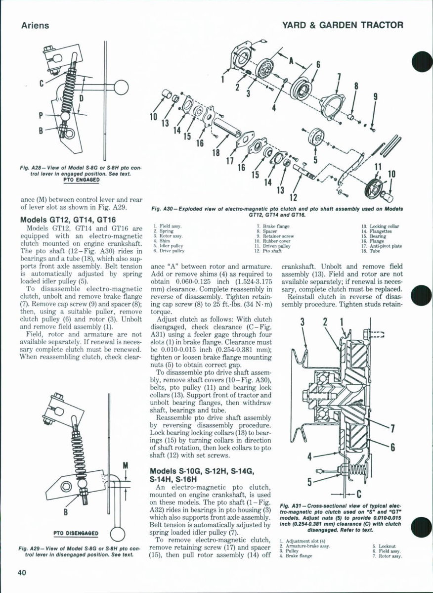
Ariens YARD & GARDEN TRACTOR Fig. A28- View of Modei S-8G or $'8H pto con- trot lever In engaged position. See text. PTO ance (M) between control lever and rear of lever slot as shown in Fig, A29, Models GT12, GT14, GT16 Models GT12, GT14 and GT16 are equipped with an electro-magnetic clutch mounted on engine crankshaft. The pto shaft (12-Fig. A30) rides in bearings and a tube (18), which also sup- ports front axle assembly. Belt tension is automatically adjusted by spring loaded idler pulley (5). To disassemble electro-magnetic clutch, unbolt and remove brake flange (7). Remove cap screw (9) and spacer (8); then, using a suitable puller, remove clutch pulley (6) and rotor (3). Unbolt and remove field assembly (1). Field, rotor and armature are not available separately. If renewal is neces- sary complete clutch must be renewed. When reassembling clutch, check clear- M PTO "T O 12 Fig. A30—Expioded view of electro-magnetic pto clutch and pto shaft assembiy used on Models GT12, GT14 and GT18. 1. Field assy. 2. Spring 3. Rotor assy. 4. Shim 5. Idler pulley 6. Drive pulley 7. Brake flange 8. Spacer 9. Retainer screw 10. Rubber cover 11. Driven pulley 12. Pto shaft 13. Locking collar 14. Flangettes 15. Bearing 16. Flange 17. Anti-pivot plate 18. Tube Fig. A29- View of Model S-8G or S-8H pto con- trol lever in disengaged position. See text. ance "A" between rotor and armature. Add or remove shims (4) as required to obtain 0.060-0.125 inch (1.524-3.175 mm) clearance. Complete reassembly in reverse of disassembly. Tighten retain- ing cap screw (8) to 25 ft.-lbs, (34 N-m) torque. Adjust clutch as follows: With clutch disengaged, check clearance (C-Fig. A31) using a feeler g ^ e through four slots (1) in brake flange. Clearance must be 0.010-0.015 inch (0.254-0.381 mm); tighten or loosen brake flange mounting nuts (5) to obtain correct gap. To disassemble pto drive shaft assem- bly, remove shaft covers (10-Fig. A30), belts, pto pulley (11) and bearing lock collars (13). Support front of tractor and unbolt bearing flanges, then withdraw shaft, bearings and tube. Reassemble pto drive shaft assembly by reversing disassembly procedure. Lock bearing locking collars (13) to bear- ings (15) by turning collars in direction of shaft rotation, then lock collars to pto shaft (12) with set screws. Models S-10G, S-12H, S-14G, S-14H, S-16H An electro-magnetic pto clutch, mounted on engine crankshaft, is used on these models. The pto shaft (1 - Fig. A32) rides in bearings in pto housing (3) which also supports front axle assembly. Belt tension is automatically adjusted by spring loaded idler pulley (7). To remove electro-magnetic clutch, remove retaining screw (17) and spacer (15), then pull rotor assembly (14) off crankshaft. Unbolt and remove field assembly (13). Field and rotor are not available separately; if renewal is neces- sary, complete clutch must be replaced. Reinstall clutch in reverse of disas- sembly procedure. Tighten studs retain- 3 2 1 Fig. A31 — Cross-sectlonat view of typical elec- tro-magnetic pto clutch used on "S" and '^T" modeis. Adjust nuts (5) to provide 0.010-0.01S inch (0.254-0.381 mm) dearance (C) with clutch disengaged. Refer to text. 1. Adjustment slot (4) 2. Armature-brake assy. 3. Pulley 4. Brake flange 5. Locknut 6. Field assy. 7. Rotor assy 40
Thank you for considering this comprehensive Workshop Service Repair Manual for the Ariens Lawn Tractor models 13989, 13990, 13948, 913002, 913003, GT-GT12-GT14-GT16, S8 S10 S14 Gear, S8 S12 S14 S16 Hydro.
This manual is an invaluable resource for both professional mechanics and DIY enthusiasts, covering every service and repair procedure with easy-to-follow step-by-step instructions and detailed illustrations. It is designed to help you save money by enabling you to perform repairs on your own.
Once downloaded, this manual is yours to keep forever. You have the flexibility to print specific pages, chapters, or the entire manual. Additionally, you can conveniently access it on your tablet or smartphone.
All models, engines, trim, and transmission types are comprehensively covered in this high-quality Service Repair Workshop Manual, ensuring that every repair and service procedure is included.
Compatibility is not an issue, as this manual is designed to work seamlessly on all PC and MAC computers, tablets, and mobile phones. The only software requirement is Adobe Reader, which is commonly pre-installed on most computers or can be downloaded for free.
Upon payment confirmation via Visa, MasterCard, or PayPal, the manual will be instantly emailed to the address provided during checkout, ensuring prompt access.
Customer satisfaction is guaranteed, and you can rely on the completeness and reliability of this Workshop Service Repair Manual for your Ariens Lawn Tractor.



 Lifetime Access




