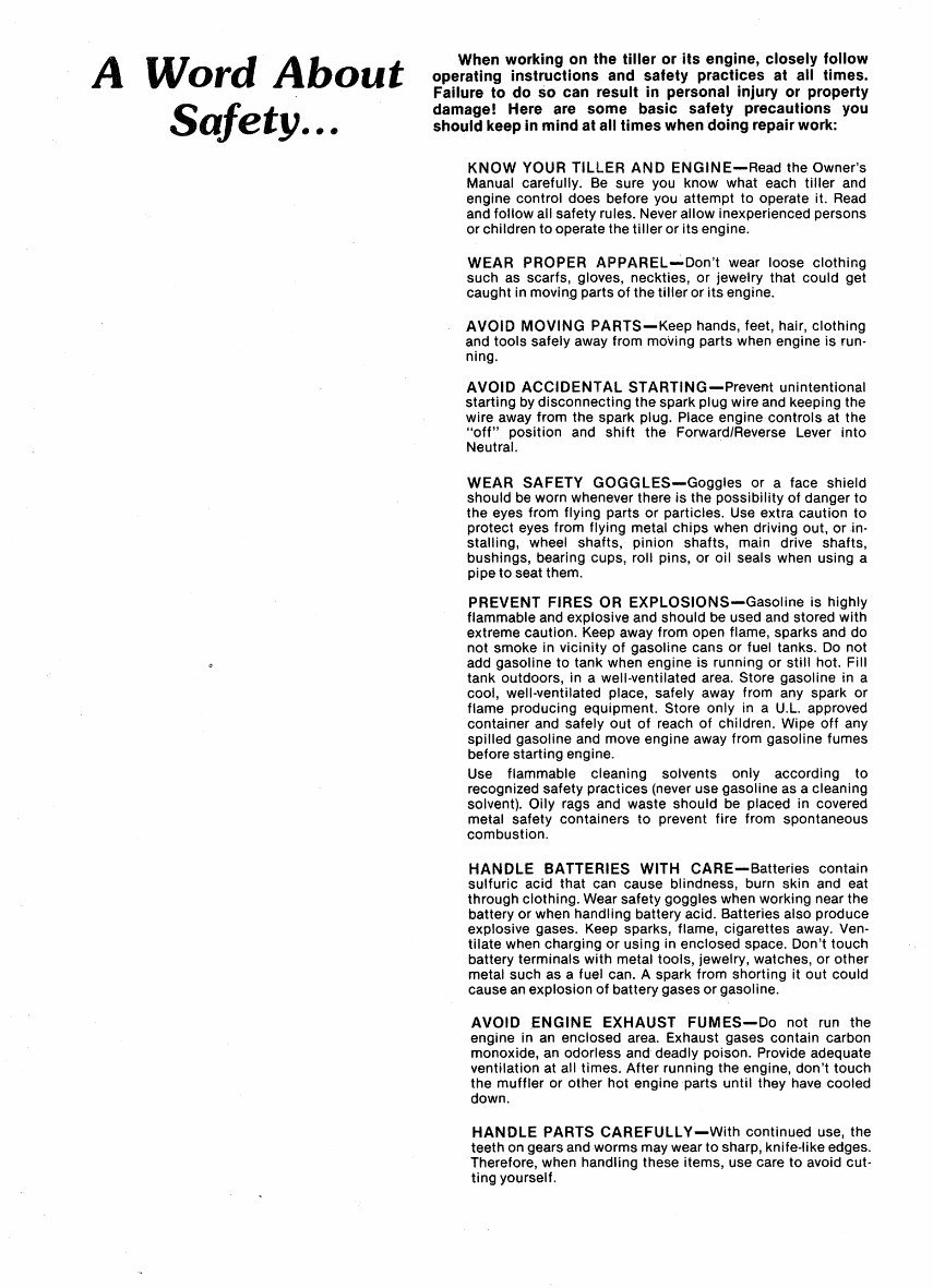
A Word About Safety ... When working on the tiller or its engine, closely follow operating instructions and safety practices at all times. Failure to do so can result in personal injury or property damage! Here are some basic safety precautions you should keep in mind at all times when doing repair work: KNOW YOUR TILLER AND ENGINE-Read the Owner's Manual carefully. Be sure you know what each tiller and engine control does before you attempt to operate it. Read and follow all safety rules. Never allow inexperienced persons or children to operate the tiller or its engine. WEAR PROPER APPAREL_,;.Don't wear loose clothing such as scarfs, gloves, neckties, or jewelry that could get caught in movin.g parts of the tiller or its engine. AVOID MOVING PARTS-Keep hands, feet, hair, clothing and tools safely away from moving parts when engine is run- ning. AVOID ACCIDENTAL STARTING-Prevent unintentional starting by disconnecting the spark plug wire and keeping the wire away from the spark plug. Place engine controls at the "off" position and shift the Forward/Reverse Lever into Neutral. · WEAR SAFETY GOGGLES-Goggles or a face shield should be worn whenever there is the possibility of danger to the eyes from flying parts or particles. Use extra caution to protect eyes from flying metal chips when driving out, or in- stalling, wheel shafts, pinion shafts, main drive shafts, bushings, bearing cups, roll pins, or oil seals when using a pipe to seat them. PREVENT FIRES OR EXPLOSIONS-Gasoline is highly flammable and explosive and should be used and stored with extreme caution. Keep away from open flame, sparks and do not smoke in vicinity of gasoline cans or fuel tanks. Do not add gasoline to tank when engine is running or still hot. Fill tank outdoors, in a well-ventilated area. Store gasoline in a cool, well-ventilated place, safely away from any spark or flame producing equipment. Store only in a U.L. approved container and safely out of reach of children. Wipe off any spilled gasoline and move engine away from gasoline fumes before starting engine. Use flammable cleaning solvents only according to recognized safety practices (never use gasoline as a cleaning solvent). Oily rags and waste should be placed in covered metal safety containers to prevent fire from spontaneous combustion. HANDLE BATTERIES WITH CARE-Batteries contain sulfuric acid that can cause blindness, burn skin and eat through clothing. Wear safety goggles when working near the battery or when handling battery acid. Batteries also produce explosive gases. Keep sparks, flame, cigarettes away. Ven- tilate when charging or using in enclosed space. Don't touch battery terminals with metal tools, jewelry, watches, or other metal such as a fuel can. A spark from shorting it out could cause an explosion of battery gases or gasoline. AVOID ENGINE EXHAUST FUMES-Do not run the engine in an enclosed area. Exhaust gases contain carbon monoxide, an odorless and deadly poison. Provide adequate ventilation at all times. After running the engine, don't touch the muffler or other hot engine parts until they have cooled down. HANDLE PARTS CAREFULLY-With continued use, the teeth on gears and worms may wear to sharp, knife~like edges. Therefore, when handling these items, use care to avoid cut- ting yourself.
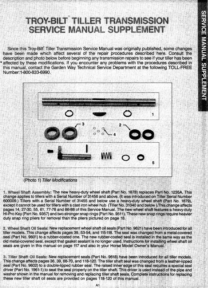
. . ' Sincatbis Troy-Bitt! TjllerTransmission Seryice Manual was originally published~ .some ch~ng~S: . have been made which affect several of tne repair procedures described here. Consu,lt the description and· photo below before beginning .any transmission repairs to see if yowr: tiller has. been .. • affected by .these modifications. If. you encounter any problems with the procedur~s described·in this marnual., contact the Garden Way Technical Service Department at the following TOLL-FREE Number: 1-800•833-6990. 00 A1
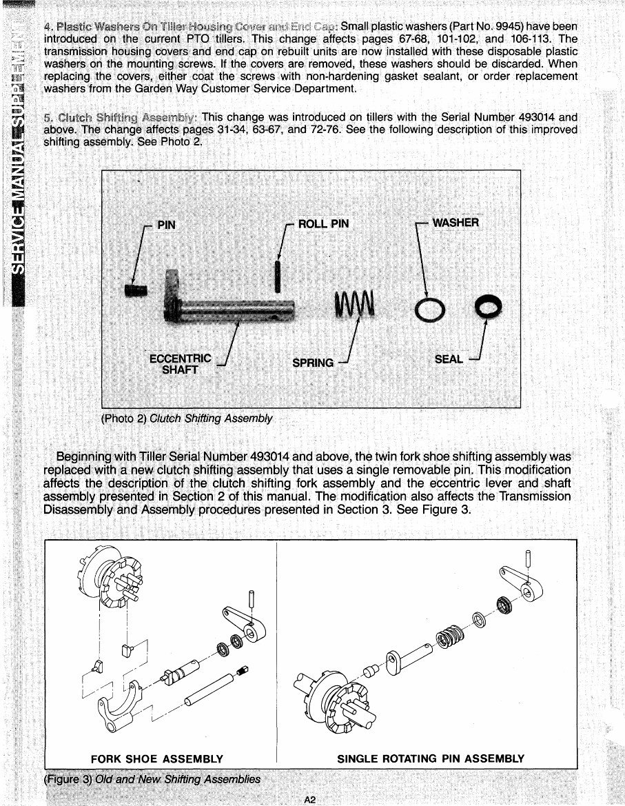
Washers TU1erHousir1g Cap: Small plastic washers (Part No. 9945) have been introduced oh the current PTO tillers. This change affects pages 67-68, 101-102, and 106-113. The transmission housing covers and end cap on rebuilt units are now installed with these disposable plastic washers on the mounting screws. lfthe covers are removed, these washers should be discarded. When replacing the covers, either coat the screws with non-hardening gasket sealant, or order replacement washers from the Garden Way Customer Service Department. Clutch Shifting This change was introduced on tillers with the Serial Number 493014 and above. The change affects pages 31-34, 63-67, and 72-76. See the following description of this improved shifting assembly. See Photo 2. (Photo 2) Clutch Sh,ifting Assembly Beginning with Tiller Serial Number 493014 and above, the twin fork shoe shifting assembly was replaced with a new clutch shifting assembly that uses a single removable pin. This modification affects the description of the clutch shifting fork assembly and the eccentric lever and shaft assembly presented in Section 2 of this manual. The modification also affects the Transmission Disassembly and Assembly procedures presented in Section 3. See Figure 3. FORK SHOE ASSEMBLY SINGLE ROTATING PIN ASSEMBLY A2
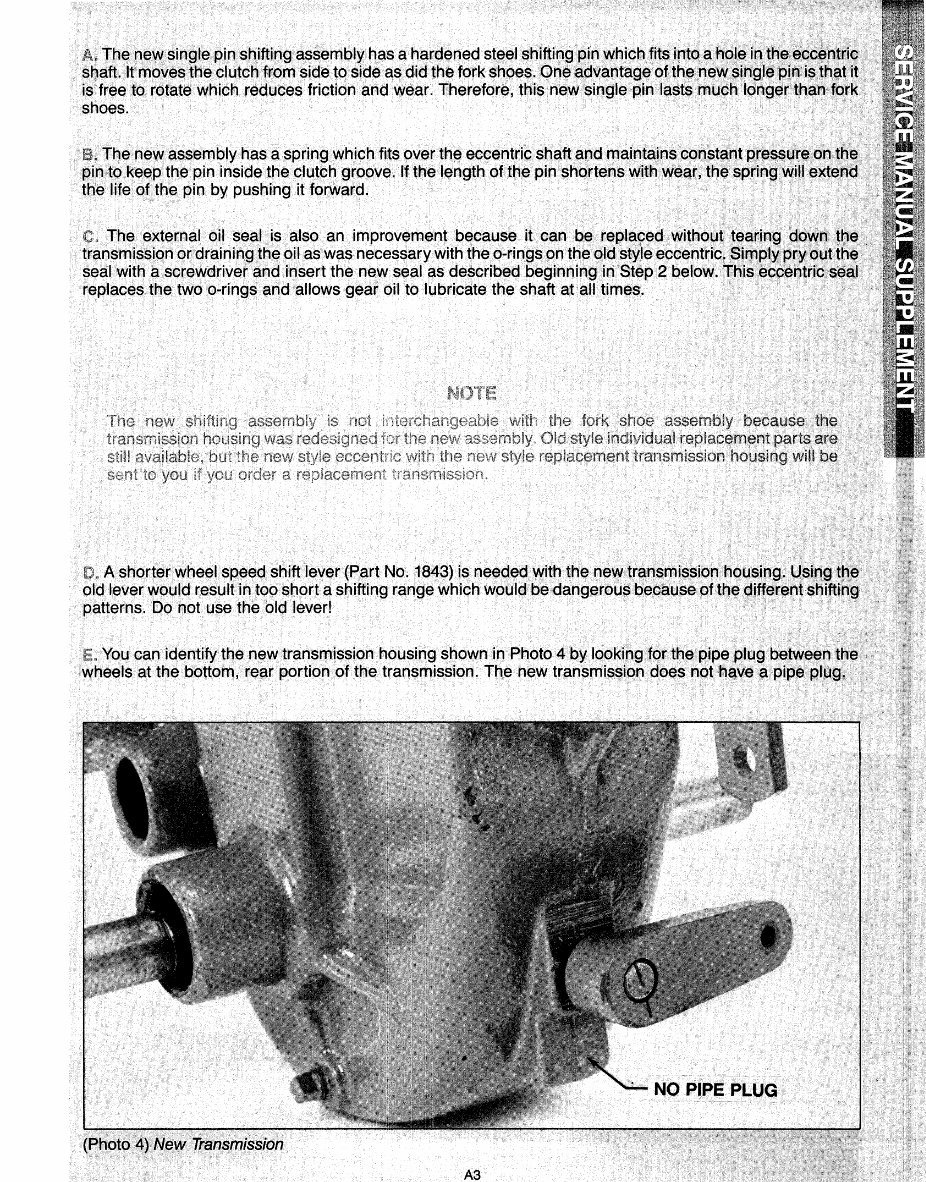
The n~wsingle pins~ifting as$embly has a hardened ste~l shiftin~ p,in Y{hich.fit$ ipto a hole, irrth~e,qpf)ht~i$ ·s!'laft. It moves the clutcn·from side to side as did the fqrk shoes .. On~ advantageotthe:new sinfjl~ptm~isthat·i~ ·. is free to. rotate•which reduces friction. and wear. Therefore, this new single pin lasts much longer: than fbrk shoes. · The new assembly has a spring which fits over the eccentric shaft apd rpaintainsconst(ihtpres~~re ()Ot~~ pin. to keep the pin inside the clutch groove. If the length of the pin shortens with wear, the spring:will extend the life of the pin by pushing it forward. The external oil.seat is. also an improvement .because it can b-e repla9ed without t~~rin~ .d8!'~t~~· transmission ·or.drainin~ ttle oil as was necessary with the o-rings on the ~ldstyle eccentric. Sin:lpl;~l' prM ()~t ~·~.~:. seal with a screwdriver and insert the new seal as described beginning in Step 2 below~ Tl1is e~9entric}seal replaces the two b-rings ~nd allows gear oil to lubricate the shaft at all times. · A shorter wheel. speed shift lever(Part No; 1843) is needed withthenew·tr~nsmission housinQ .. · Usingt~·e old lever would result in too short a shifting range which would be dangerous because ofthe C(:li1ferentshifUng patterns. Do not use the old lever! You can identify the new transmission housing shown in Photo 4 by looking ,tor the. pipe plug.'between the wheels at the· bottom, ·rear portion· of the transmission. The new transmission does not have a pipe plug.· (Photo 4}New Tr;3nsmission A3
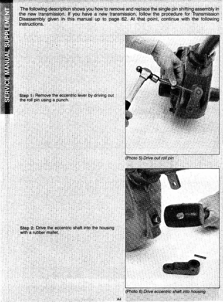
The follp\A/il'lQ d~S,cripti()!l ~hows you how-to remov~ ~nd --repl~o~ the single pin shifting·a~s~mbly in the ne~ tran$rni$sion.: If' you have a new transmission, follow the procedure for Tr(ins_mission Disass~mbly given in this manual up to page 62. At that point, continue with the following instructions. t ' St•P t:-.Rernqve-·the:eceentric: lever by drlving. out the: roll -pin using· a punch~ st~p 2! ·Qti"-~-~~~ .. ~ccentric shaft :into the housing with· a rut)b,e(rnaltet~ A4
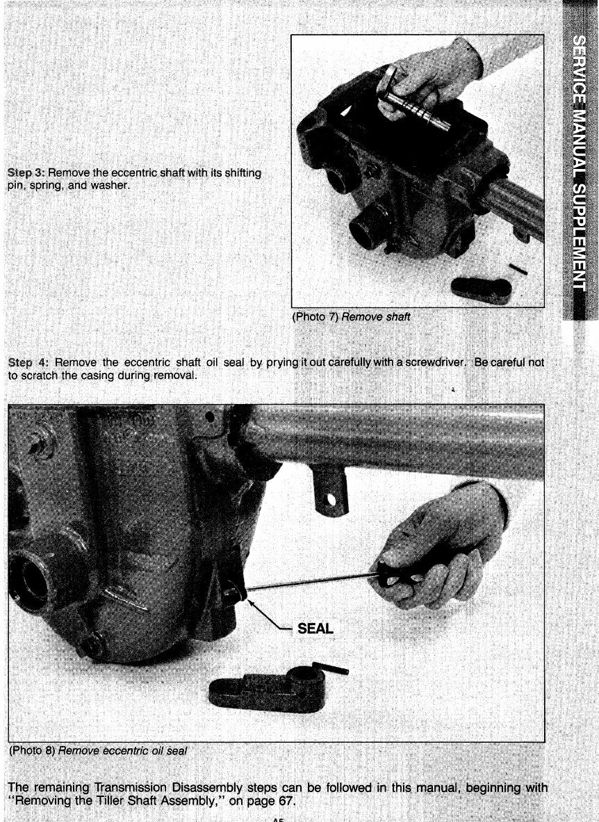
S:tep, 3,: R~move; ~he e9centrio shaf't W:itt\ its shifting pin, spring, :and :Washer. S~ep 4: R~move the eccentric shaft, oil seal by to' scratch', the casing during removal. ~·SEAL f#~, ~~;r)l~n~Ji~~!lliMl~a.i~~~mbl~ Steps ••~· •be •tol.llowectrJni,~tni~~·h~lt11l~IJilldi. ''A:~r:r;l~V~tt:l~.'·,tn~ ifif:l~~: $~~f;t.~$s~mcly, ~' , on. page f,71 ,
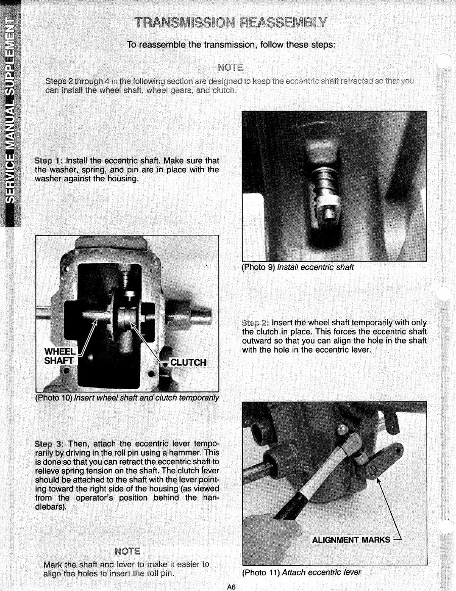
To reassemble the transmission, follow these steps: Steps 2 through 4 in the tollf">wlr1a ...,.,.,'""~'·'"'' can install the wheel Step•·1: Install the. eccentric shaft. Make sure that the washer, sprjng, . and pin are in place with the washer against the .• housing. Step 3: Then, .attach the eccentric lever tempo- rarily t>~ driving in the roll pin using a hammer. This is done.so that you can retract the eccentric shaft to relieve ·$Pring tension on the shaft. the clutch fever should be attached to the shaft with th~ lever pdJnt- ing toward the right side of the housing (as viewed from· .the operator's position .behind the han- dlebars). Mark· the shaft and lever to make it easier to align the. holes to insert the roll A6 to (Photo 9) Install eccentric shaft Insert the wheel shaft temporarily with only the clutch in place. This forces the eccentric shaft outward so that you can align the hole in the shaft with the hole in the eccentric lever. (Photo 11) Attach eccentric lever
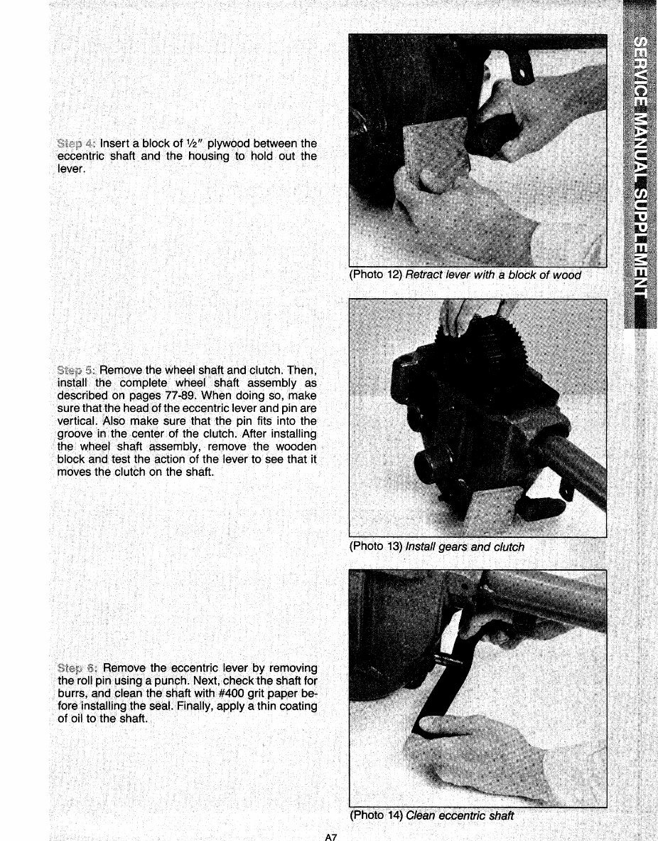
Insert a block of 1 12" plywood between the eccentric shaft and the housing to hold out the lever. ZS'~ter,J~ Remove the wheel shaft and clutch. Then, install the complete wheel .shaft assembly as described on pages 77-89. When doing so, make sure thatthe·headof the eccentric lever and pin are vertical. Also make sure that the pin fits into the groove in the center of the clutch. After installing the wheel shaft assembly, remove the wooden block and test the action of the lever to see that it moves the clutch on the shaft. Remove the eccentric lever by removing the roll pin using apunch. Next, check the Shaft for burrs, and clean the shaft with #400 grit paper be~ fore installing the seal. Finally, apply a thin coating of oil to the shaft. A7
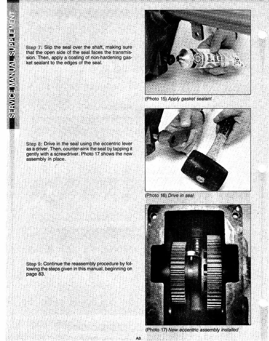
Step 7! Slip. the seal over the shaft, making sure that the . open side of• the. seal faces the transmis .. sion. Then, apply a coating of non.;hardening gas- ket sealant to the edges of· the seal. Step ~=. Drive in the seal using the eccentric lever as a driveL Then1 counter-sinktheseal by tapping it gently with a screwdrive·r. ·Photo 17 shows the new assembly in place. Step Continue the reassembly procedure by fol- lowing the steps given in this manual, beginning on page 83. (Photo 15) Apply gasket· sealant AS
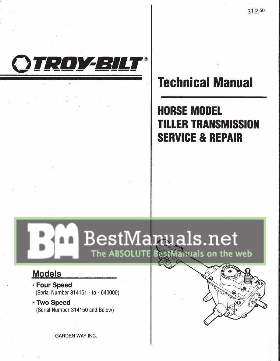
This complete factory Troy-Bilt tiller transmission Horse Model repair and service workshop manual for roto tillers includes the necessary instructions to maintain and service your tiller using detailed diagrams and manufacturer's specifications. The manual covers four-speed models with serial numbers 314151 to 640000 (1978 and up) and two-speed models with serial number 314150 and below (1962-1978).
The improved manual features bookmarks, searchable text, index, and improved quality. It is in English and comes in a 165-page format. Compatible with all versions of Windows, Mac, iOS, BB, Android, etc., the manual is searchable, bookmarked, and indexed for easy access.
The contents of the manual include safety information, supplements, introduction, serial number details, general information, things to do, know and watch out for, transmission disassembly and reassembly, special repairs and procedures, and transmission troubleshooting.
This manual is clear and written in a way so that just about anybody can follow it. It is in an easy-to-read file format and can be viewed on any computer, zoomed, and printed. It is completely searchable and bookmarked, making it easy to find what you are looking for. Additionally, it has lots of pictures, diagrams, illustrations, and charts.
Technical details and instructions you will need are included. The manual is immediately accessible and can be saved, printed, and closed. You can print a few pages at a time or the entire manual without worrying about dirty, torn, or missing pages.
Additional information: Some documents may require the newest version of Acrobat Reader to display correctly. Should you have any problems reading your document, please initially try upgrading to the latest version of Adobe Acrobat Reader. For any other manuals you might need, feel free to email me.


 Lifetime Access




