

Gilson Snow Thrower service repair manual maintenance
What's Included?
Fast Download Speeds
Online & Offline Access
Access PDF Contents & Bookmarks
Full Search Facility
Print one or all pages of your manual
Printed in U.S.A.
Snowthrowers
Gilson Brothers Company, Box 152, Plymouth, Wisconsin 53073
Gilson Brothers Company (Canada) Ltd., 3325 Orlando Drive, Mississauga, Ontario
No. SM1201
GlLSON BROTHERS COMPANY, BOX 152, PLYMOUTH, WISCONSIN 53073
n
SNOW THROWERS
Page
.............................. 4 H.P. Model 3-14
Set Up
Maintenance & Lubrication
General Operational Adjustments
Service Manual
5 & 8 H.P. Friction Drive Model .............. 15-22
Set Up
Maintenance & Lubrication
General OperationalAdjustments
Service Manual
.................. 8 H.P. Gear Drive Model .23-37
Set Up
Maintenance & Lubrication
General Operational Adjustments
Service Manual
Refer to Service Bulletins for additional information
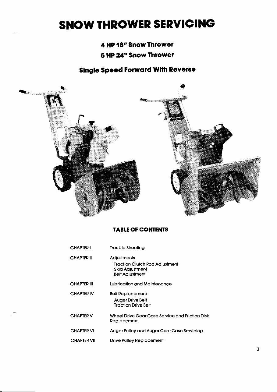
SNOW THROWER SERVICING
4 HP 18" Snow Thrower
5 HP 24" Snow Thrower
Single Speed Forward With Reverse
TABLE OF CONTENTS
CHAPTER I Trouble Shooting
CHAPTER II Adjustments
Traction Clutch RodAdjustment
Skid Adjustment
Belt Adjustment
CHAPTER Ill Lubricationand Maintenance
CHAPTER IV Belt Replacement
Auger Drive Belt
Traction Drive Belt
CHAPTER V Wheel Drive Gear Case Service and Friction Disk
Replacement
CHAPTER VI Auger Pulley and Auger Gear Case Servicing
CHAPTER VII Drive Pulley Replacement


s o SNOW THROWER
-.
1EPARATION FOR OPERATION
ASSEMBLY
Your Snow Thrower is factory assembled except for
@
handle assembly,handle brackets, traction clutch rod,
handle grips and shifter knob.
1. Attach handle bracketsto frame assembly with four
3/8-16 x 1/2 hex. cap screws and lock washers (Fig.
1).
2. Attach handle to handle brackets with four acorn
head bolts, lock washers and hex. nuts (Fig. I).
3. Attach traction clutch rod to control lever assembly
(Fig. 2) with cotter pin and flat washer. Refer to sec-
tion on traction clutch rod adjustment for placing
into shift arm holes.
4. Slip grips on handle bar.
5. Attach knob to traction shifter control (Fig. I].
Follow these instructions for proper installation of trac-
tion clutch rod after handle is attached to frame and
rod attachedto shift lever.
FIG. 1
FIG. 2
0
Pull and push unit.Wheels
@) should turn easily.
If they are, no further adjustment
@ should be required.
MODEL
55008
55020
Place Shift
Lever In The
Neutral (N)
Position.
Attach Lower
End Of Control
Rod lnto Center
HoleOf Shift Arm
And Secure With
Spring Clip.
Pull Shift Lever
Back lnto The Re-
verse (R) Position
And Ahead lnto
The Forward (F)
Position To See If
These PositionsAre
Are Approximately
'The Same Distance
From The Neutral
(W) Position.
If Reverse Is
Further Away
From Neutral
Than Forward,
Move Lower End
Of Control Rod
Down One Hole In
Shift Arm.
li Forward Is
Further Away
From Neutral
Than Reverse,
Move Lower End
Of Control Rod
Up One Hole In
Shift Arm.
Place Shift
Lever In The
Neutral [W)
PositionAnd
Start Engine.
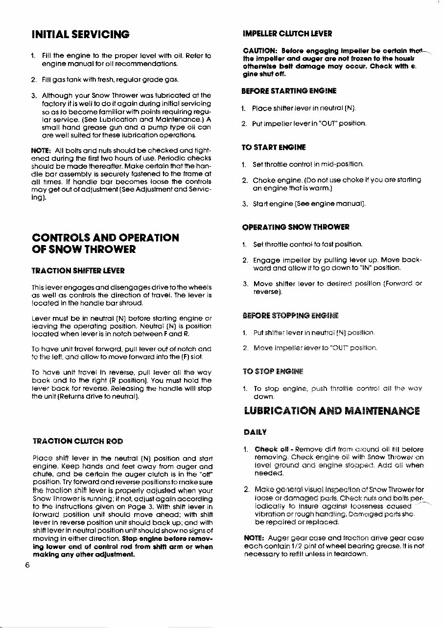
INITIAL SERVICING
IMPELLER CLUTCH LEVER
1. Fill the engine to the proper level with oil. Refer to
engine manual for oil recommendations.
2. Fill gas tank with fresh, regular grade gas.
3. Although your Snow Thrower was lubricated at the
factory it is well to do it again during initial servicing
so as to become familiar with points requiring regu-
lar service. (See Lubrication and Maintenance.)A
small hand grease gun and a pump type oil can
are well suited for these lubrication operations.
WE: All bolts and nuts should be checked and tight-
ened during the first two hours of use. Periodic checks
should be made thereafter. Make certain that the han-
dle bar assembly is securely fastened to the frame at
all times. If handle bar becomes loose the controls
may get out of adjustment (SeeAdjustment and Servic-
ing).
COMROLS AND OPERATION
OF SNOW THROWER
TRACTION SHIRER LEVER
This lever engages and disengagesdriveto the wheels
as well as controls the direction of travel. The lever is
located In the handle bar shroud.
Lever must be in neutral [NJ before stafling engine or
leaving the operating position. Neutral (N) is position
I~cated when lever is in notch between F and R.
To have unit travel forward, pull lever out of notch and
fo the left, and ailow to move forward into the (F) slot.
To have unit travel in reverse, pull lever all the way
back and to the right (R position). You must hold the
lever back for reverse. Releasing the handle will stop
the unit (Returnsdrive to neutral).
CAUTION: Before engaglng impeller be certain t h a L
the impeller and auger are not frozen to the houris
ottaemlre belt damage may occur. Check wlVh cu.
gine shut off.
BEFORE STARTING ENGINE
1. Place shifler lever in neutral (N).
2. Put impeller lever in "OUT" position.
TO START ENGINE
4. Set throttle control in mid-position.
2. Choke engine. (Do not use choke if you are star?ing
an engine that is warm.)
3. Start engine [See engine manual).
OPERATING SWW THROWER
1. Set throttle control to fast position.
2. Engage impeller by pulling lever up. Move back-
ward and allow it to go down to "IN" position.
3. Move shifter lever to desired position [Fonvard or
reverse].
1. Put shiner !ever in neutral [N] position.
2. Move impeller lever ts "OUT" position.
I. To stop engine, push %?sotile control ail the way
down
LUBRICATION AND MAIMENANCE
TRACTION CWTGH ROD
Place shifl lever in the neutral (N) position and start
engine. Keep hands and feet away from auger and
chute, and be certain the auger clutch is in the "off"
position.Try foward and reverse positionsto makesure
the traction shifi lever is properly adjusted when your
Snow Thrower is running; if not, adjust again according
to the instructions given on Page 3. With shift lever in
fsmaad position unit should move ahead; with shift
lever in reverse position unit should back up; and with
shift lever in neutral positionunit should show nosignsof
moving in either direction. Stop englne before remsv-
ing lower end of eontroi rsd from &if? arm or when
making any omer ac8gushent.
6
4. Cheek oil - Remove dirt from around oil fill before
removing. Check engine sli wi% Snow Thrower on
level ground and engine stopped. Add oil when
needed.
2. Make general visuaB inspection of Srbsw Thrower for
loose or damaged parts. Cheek nuts and bolts per-
iodlcaily to insure against looseness caused
-,
vibration or rough handling.Damaged sho
be repaired or replaced.
WE: Auger gear case and traction drive gear case
each contain 1/2 pint of wheel bearing grease. It is not
necessary to refill unless in teardown.
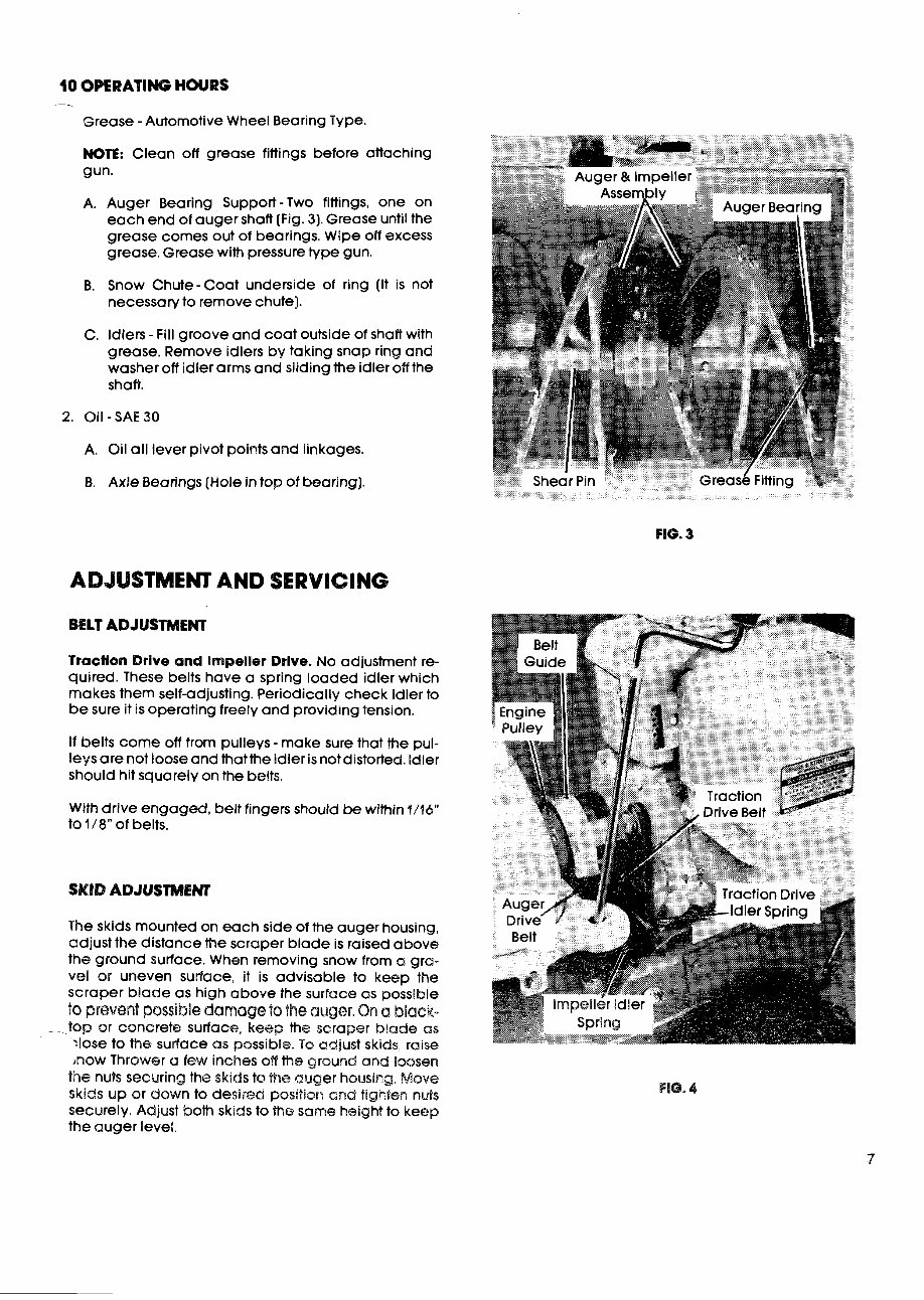
10 OPERATING HOURS
Grease -Automotive Wheel Bearing Type.
NOTE: Clean off grease fittings before attaching
gun.
A. Auger Bearing Support-Two fittings, one on
each end of auger shaft (Fig. 3). Grease until the
grease comes out of bearings. Wipe off excess
grease. Grease with pressuretype gun.
B. Snow Chute-Coat underside of ring (It is not
necessary to remove chute].
C. Idlers - Fill groove and coat outside of shaft with
grease. Remove idlers by taking snap ring and
washer off idler arms and sliding the idler off the
shaft.
A. Oil all lever pivot points and linkages.
B. Axle Bearings(Holein top of bearing).
FIG. 3
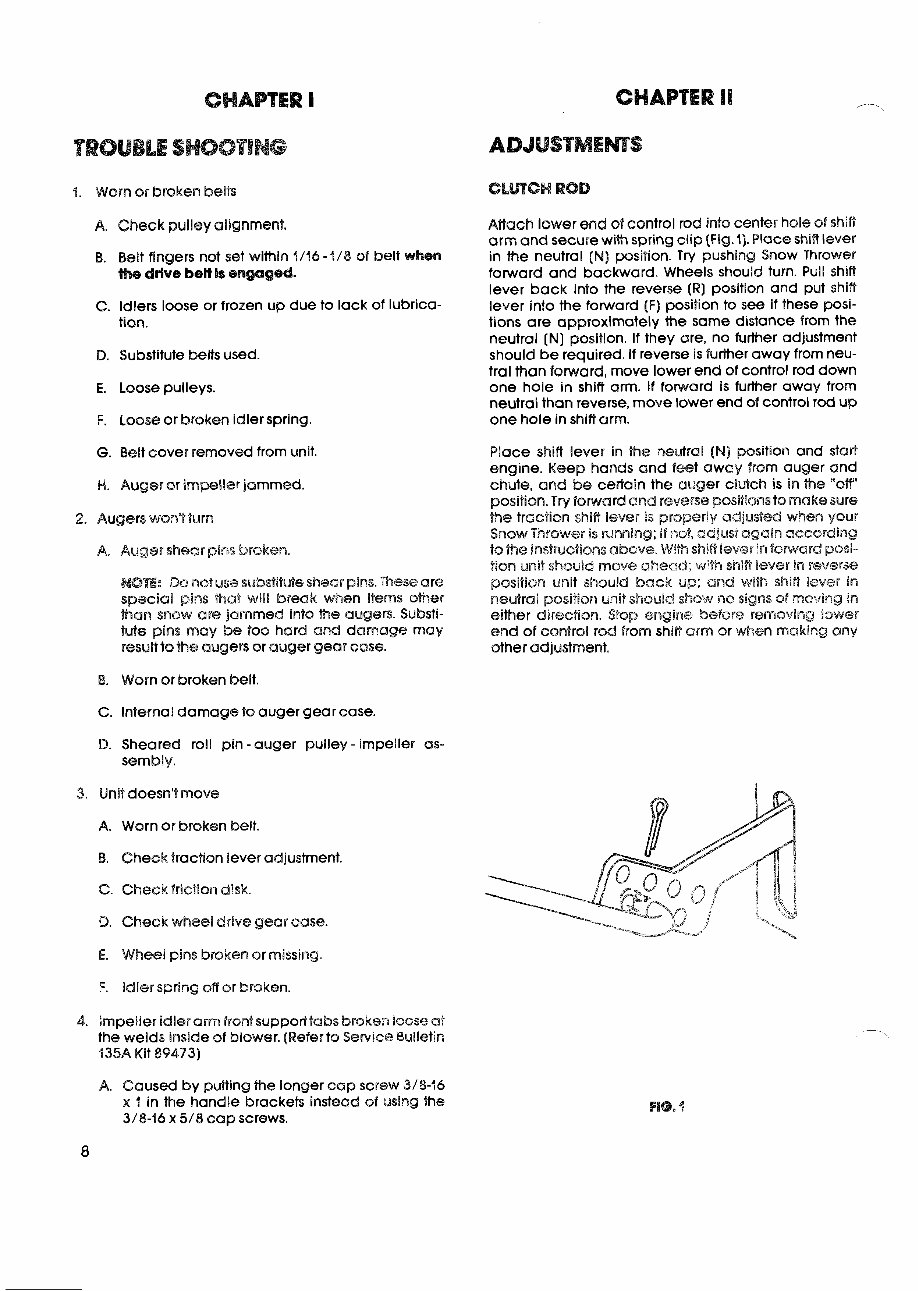
ADJUSTMEHT AND SERVICING
BELT ADJUSTMEHT
Traction Drive and lrnpeller Drive. No adjustment re-
quired. These belts have a spring loaded idler which
makes them self-adjusting. Periodically check idler to
be sure it is operating freely and providing tension.
If belts come off from pulleys - make sure that the pul-
leys are not loose and thatthe idler is not distorted.Idler
should hit squarely on the belts.
With drive engaged, belt fingers should be within 4/46"
to 1/8" of belts.
SKID ADJUSTMENT
The skids mounted on each side of the auger housing,
adjust the distance the scraper blade is raised above
the ground surface. When removing snow from a gra-
vel or uneven surface, it is advisable to keep the
scraper blade as high above the surface as possible
to prevent possible damage to the auger. On a black-
- top or concrete surface, keep the scraper blade as
:lose to the sudace as possible. To adjust skids. raise
mow Thrower a few inches off the ground and loosen
the nuts securing the skids to the auger housing. Move
skids up or down to desired position and tighten nuts
securely. Adjust both skids to the same height to keep
the auger level.
FIG. 4
CHAPTER B
TROUBLE SHOOTING
4. Worn OF broken belts
A. Check pulley alignment.
B. Belt fingers not set within 4/46 -f/8 sf belt when
the drlve bett Is engaged.
C. Idlers loose or frozen up due to lack of lubrica-
tion.
D. Substitute belts used.
E. Loose pulleys.
F. Lossa or taroken idler spring.
G. Belt cover removed f r ~ m unit.
H. Auger or impller jammed.
2. Augers won't turn
A~ Auger shew plns broken.
WE: Do nod usa substitute shear piws. These are
special pins &at "will break when items other
%an snow are? jammed into the augers. Substi-
tute plns may be too herd and damage may
result to %-ae augers or auger gear case.
B. Worn or broken belt.
C. Internal damage to auger gear case.
D. Sheared roll pin -auger pulley - impeller as-
sembly.
3. Unit doesn't move
A. Worn or broken belt.
5. Check traction lever adjustment.
C. Check friction disk.
B. Check wheel drive gear case.
E. Wheel piws broken or missing.
F. idler spring off or broken.
4. Impeller idler arm front suppor68abs broken Oo~ae a.t
the welds inside ef blower.(Referto Sewice Bulletin
135A Kit $9473)
A. Caused by puSPing the longer cap screw 3/8-46
x 3 in the handle brackets instead of using :he
3/8-16 x 5/8 cap screws.
Aflach lower end of control rod into center hole of $Riff
arm and secure with spring clip (Fig. I]. Place shin lever
in the neutral (N) position. Try pushing Snow Thrower
forward and backward. Wheels should turn. Pull shift
lever back into the reverse (R) position and put shift
lever into the forward (F) position to see if these posi-
tions are approximately the same distance from the
neutral (N) position. If they are, no further adjustment
should be required. If reverse is further away from neu-
tral than forward, move lower end of control rod down
one hole in shift arm. If forward is further away from
neutral than reverse,move lower end of control rod up
one hole in shift arm.
Place shift lever in the neutral (Nj position and star3
engine. Keep hands and feet away from auger and
chute, and be certain the auger clutch is in he "OW'
position. T~P/ forward and revene pO%itir;Pns to make sure
the traction shifi iever Is properly adjusted when your
Swsw Thrower is mwning; If 14~9, adjust again a~~ording
to 'he instruet!snsabovg. LVWi sbifi igevsb In faward posi-
tian unlB should move ahecrad; with hlfi lever in revsne
position unit should back up; and wim shift lever in
neutral position unit should shmv nnc? signs sf rnm~ing 8n
either direction. Stop englr%e befoss removing lower
end of eontr~l rod from sh i W aim or when making any
other adjustment.
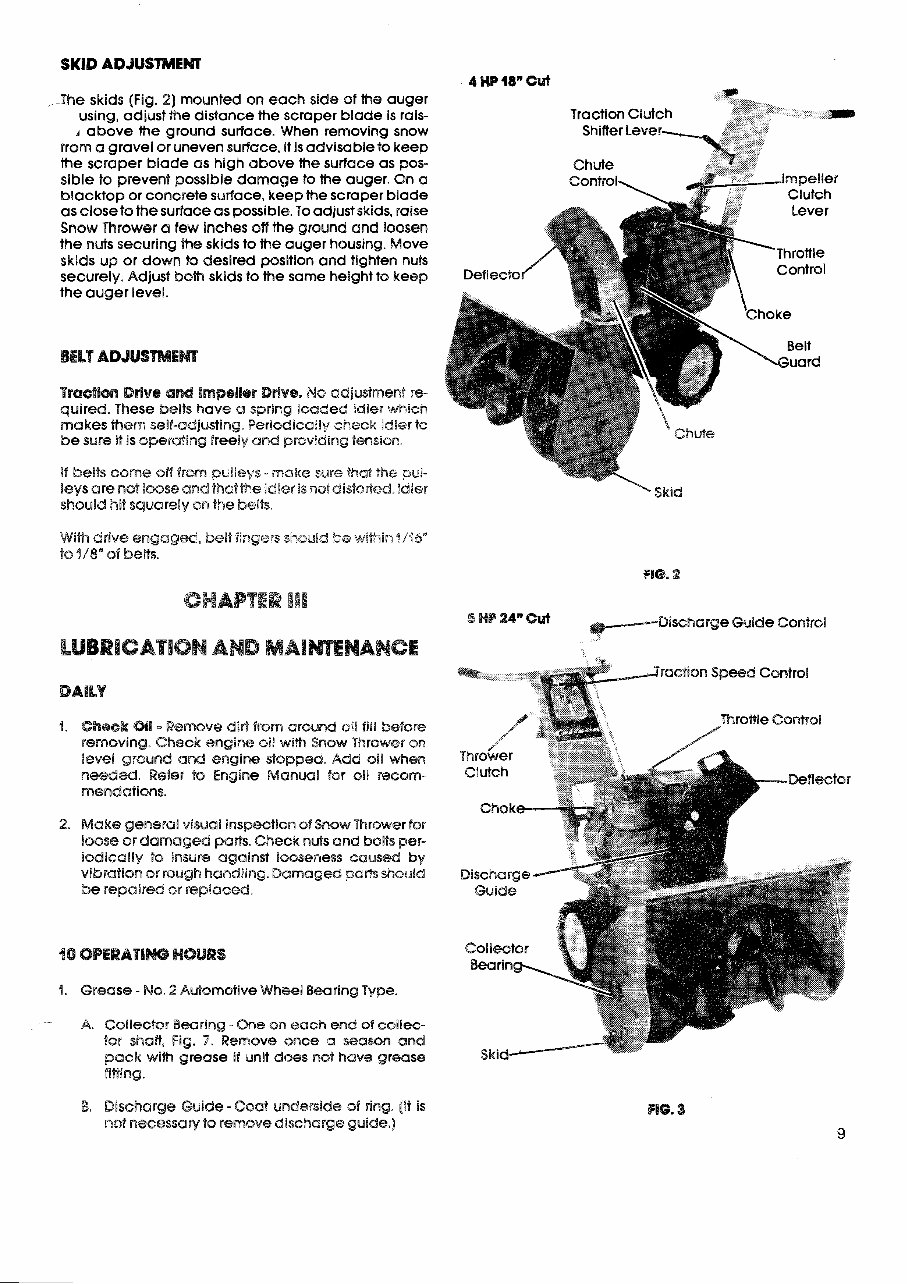
SKID ADJUSTMENT
4 HP 18" Cut
The skids (Fig. 2) mounted on each side of the auger
using, adjust the distance the scraper blade is rais- Traction Clutch
A above the ground surface. When removing snow Shifter Lever-
rrsm a gravel or uneven surface, it is advisable to keep
the scraper blade as high above the surface as pos-
sible to prevent possible damage to the auger. On a
blacktop or concrete surface, keep the scraper blade
as closets the surface as possible.To adjust skids, raise
Snow Thrower a few inches off the ground and loosen
the nuts securing the skids to the auger housing. Move
skids up or down to desired position and tighten nuts
securely. Adjust bslh skids k the same height to keep Deflecto
the auger level.
BELT ADSIISWBWEW
TB~(G@OW Ddw8 and impeller Ddve. No adgustmen! re-
quired. These belts have a spring loaded idler which
makes %hem self-adjusting.periodicadly check lases to
be sure it Is operating freeiy and proviaing tension.
I% belts come sfl from pulleys - ,make sure that the pus-
leys are ws8 loose and thatme :dBerBs i?atdi~t~ded,?di@r
shsuid hit squarely on the $sits
2Vih drive en gag^, belt fi~gers s!-@uk2 ". atitherin 4/16"
to "$8" sf beits.
f 10.2
GHAPTER III
5 HB 24" cut
DischargeGuide Control
LUBRICATION AND MAI WENANCE
d >ractJon S~wd Control
1. Chsek OBI - Remove diri from around oil fill before
removing. Check engine 019 wi% Snow Thrower on
OeveI ground and engine stopped. Add oil when
weeded. Refer $0 Engine Manual far oil ;eccsm-
menaafions.
2. Make general visual inspection of Snow Thrower for
loose or damaged parts. Check nuts and bolts per-
lsdicallly ts insure against Bosseasess caus& by
vibration or rough handling. Damaged parts shouid
be repaired sr repicreed.
1. Grease - No. 2 Adomotive Wheel Bearing Type.
- A. Collector Bearing -One ow each end of collec-
Zsr shaff, Fig. 7. Remove once a season and
pack with grease if unit does not have grease
fi88ing.
4 '
Thrower
Discharge
Guide
Skid
8. Discharge Guide - Coat underside of ring. [it is
nsl necessaw to remove discharge guide.]
C. Wheel Assemblies -Remove wheels and coat
axle shafts.
MTE: Collector gear case and traction drive gear
case each contain 1/2 pint of wheel bearing
grease. It is not necessary to refill unless in tear-
down.
2. Oil - Engine Oil. (S.A.E. 5W-20 or S.A.E. 10W)
A. QII all lever pivot points and linkages.
B. Axle bearings.
CHAPTER IV
BELT REPWCEMEM
The belts on this Snow Thrower are specifically de-
signed and engineered to provide long service. If belt
replacement is required, order by part number to be
sure you have a belt that will provide the life and ser-
vice required. DO NQT USE SUBST~PWE BELTS.
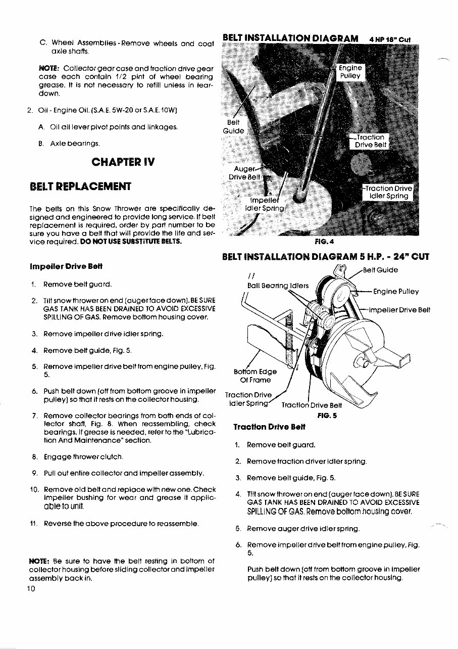
impeller Drive Bett
4. Remove belt guard.
2. Tilt snowthroweronend [augerfacedown]. BE SURE
GAS TANK HAS BEEN DRAINED TO AVOID EXCESSIVE
SPILLING OF GAS. Remove boRom housing cover.
3. Remove impeller drive idler spring.
4. Remove belt guide, Fig. 5.
5. Remove impeller drive belt from engine pulley, Fig.
5.
6. Push belt down (off from bottom groove in impeller
pulley) so that it rests on the collector housing.
- 24" CUT
elt Guide
FIG. 4
BELT ledSBAbLATCQN DIAGRAM 5 H.P. - 24" CUT
7. Remove collector bearings from both ends of col- FIG. 5
lector shaft, Fig. 8. When reassembling, check Traction BeH
bearings. If grease is needed, refer to the "Lubrica-
tion And Maintenance"section.
1. Remove belt guard.
8. Engage thrower clutch.
2. Removetraction driver idler spring.
9. Pull out entire collector and impeller assembly.
3. Remove belt guide, Fig. 5.
40. Removeold belt and replace with new one. Check
impeller bushing for wear and grease it applic-
4. Tilt snowthrower on end (auger facedown). BE SURE
able to unit.
GAS TANK HAS BEEN DRAINED TO AVOID EXCESSIVE
SPILLING OF GAS. Remove bstiom housing cover.
11. Reverse the above procedureto reassemble. --
5. Remove auger drive idler spring.
,
6. Remove impellerdrive beltfromengine pulley,Fig.
5.
WE: Be sure to have the belt resting in boRom of
collector housing before sliding collector and impeller Push belt down (off from bottom groove in impeller
assembly back in.
pulley) so that it rests on the collector housing.
10
You're Reading a Preview
What's Included?
Fast Download Speeds
Online & Offline Access
Access PDF Contents & Bookmarks
Full Search Facility
Print one or all pages of your manual
$39.99
Viewed 95 Times Today


Secure transaction
What's Included?
Fast Download Speeds
Online & Offline Access
Access PDF Contents & Bookmarks
Full Search Facility
Print one or all pages of your manual
$39.99
Get the comprehensive maintenance service manual for the Gilson Snow Thrower. This manual covers the ST series and includes 38 pages of detailed instructions, along with exploded views and images. It is designed for use with 5 & 8 HP friction drive and 8 HP gear drive snow throwers. Whether you're a professional mechanic or a DIY enthusiast, this manual is an invaluable resource for keeping your snow thrower in top condition.
Additionally, we offer the Briggs engine manual on Tradebit for your convenience.


