

Craftsman 536.886621 Snowblower Owners Manual
What's Included?
Fast Download Speeds
Online & Offline Access
Access PDF Contents & Bookmarks
Full Search Facility
Print one or all pages of your manual
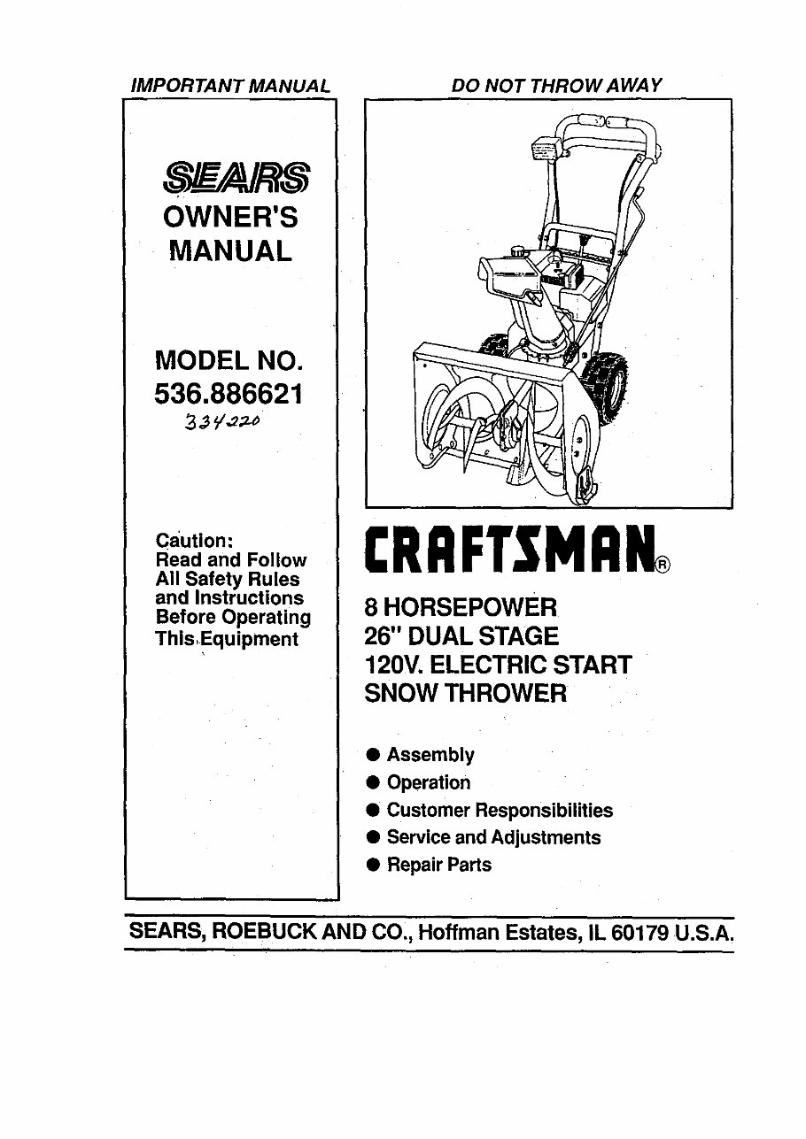
IMPORTANT MANUAL DO NOT THROW A WAY
OWNER'S
MANUAL
MODEL NO.
536.886621
caution:
Read and Follow
All Safety Rules
and Instructions
Before Operating
This,Equipment
CRRFTSMRN®
8 HORSEPOWER
26" DUAL STAGE
120V. ELECTRIC START
SNOW THROWER
• Assembly
• Operation
• Customer Responsibilities
• Service and Adjustments
• Repair Parts
SEARS, ROEBUCK AND CO., Hoffman Estates, IL 60179 U.S.A.
SAFETY RULES
CAUTION: ALWAYS DISCONNECT SPARK PLUG WIRE AND
A A
,L PLACE WIRE WHERE IT CANNOTt CONTACT SPARK PLUG AL
TOPREVENT AOO,DENTAL START.NG W.EN SETT,.G UP
TRANSPORT,N ADJUST,N OR MAK,N REPA,RS
IMPORTANT
SAFETY STANDARDS REQUIRE OPERATOR PRESENCE CONTROLS TO MINIMIZE THE
RISK OF INJURY. YOUR SNOW THROWER IS EQUIPPED WITH SUCH CONTROLS. DO NOT
AI-FEMPT TO DEFEAT THE FUNCTION OF THE OPERATOR PRESENCE CONTROL UNDER
ANY CIRCUMSTANCES.
TRAINING
1.
Read the operator's manual carefully. Be
thoroughly familiar with the controls and the
proper use of the snow thrower. Know how to
stop the snow thrower and disengage the
controls quickly.
2. Never allow children to operate the snow thrower
and keep them away while It Is operating. Never
allow adults to operate the snow thrower without
proper Instruction. DO not carry passengers.
3. Keep the area of operetlon clear of all persons,
particularly small children, and pets.
4. Exercise caution to avoid slipping or falling,
especially when operating In reverse.
PREPARATION
1. Thoroughly Inspect the area where the snow
thrower Is to be used and remove all doormats,
sleds, boards,wires, and other foreignobjects.
2. Disengage all clutches and shift Into neutral
before starting the engine (motor).
3. Do not operetethe snowthrowerwithoutweadng
adequate winter outer garments.Wear footwear
that will Improve footingon slipperysurfacse.
4. Handle fuel wIth care; it Is highlyflammable.
(a) Use an approvedfuel container.
(b) Never remove fuel tank cap or add fuel to a
running engine or hot engine.
(c) Fill fuel tank outdoors with extreme care,
Never fill fuel tank Indoors.
(d) Replace fuel tank cap securely and wipe up
spilled fuel.
(e) Never store fuel or snow thrower with fuel In
the tank Inside of a building where fumes may
reach an open flame or spark.
(f) Check fuel supply before each use, anowlng
space for expenslonas the heatofthe engine
(motor) and/or sun can cause fuel to expend.
5. Use extsnsloncords snd racaptaclesasspecified
by the manufacturer for all snow throwers with
eiactrlc drive motors or electric starting motors.
6. Adjust the snow thrower height to clear gravel or
crushed rock surfaces,
7. Never aftempt to make any edjustmsnts while the
engine (motor) Is running (except when
specifically recommended by the manufacturer).
8. Let engine (motor) and snow thrower adjust to
outdoor temperatures before starting to clear
SNOW.
9. Always weer safety glasees or eye shields du ring
operetlon or while performing an adjustment or
repair to protect eyes from foreign objects that
may be thrown from the snow thrower.
OPERATION
1. Do not put hands or feet near or under rotating
parts. Keep clear of the discharge opening at all
times.
2. Exercise extreme cautio n when operating on or
crossing gravel drives, walks, or roads. Stay alert
for hidden hazards or traffic.
3. After striking a foreign object, stop the engine
(motor), remove the wire from the spark plug,
disconnect the cord on electric motors,
thoroughly Inspect the snow thrower for any
damage, and repair the damage before restarting
and operating the snow thrower.
4. If the snow thrower should start to vibrate
abnormally, stop the (motor) and check
Immediately for the cause. Vlbretlon Is gsnerelly
a warning of trouble.
5. Stop the snglne (motor) wheheveryou leavethe
operating position, before unclogging the auger/
Impeller housing or dlsnherge guide, and when
making a ny repairs, adjustments, or Inspections.
6. When cleaning, repairing, or Inspecting, make
cartaln the auger/impeller and all moving parts
have stopped. Disconnect the spark plug wire
and keep the wire away from the plug to prevent
accidental starting.
7. Take all possible precautions when leaving the
snow thrower unattended. Disengage the auger/
Impeller, shift to neutral, stop engine, and
remove key.
2
SAFETY RULES
8. DO not run the engine indoors, except when starting
the engine and for transporting the snow thrower In
or out of the building. Open the outside doors;
exhaust fumes are dangerous (containing CARBON
MONOXIDE, an ODORLESS and DEADLY GAS).
9. Do not clear snow across the face of slopes.
Exercise caution when changing direction on
slopes. Do not attempt to clear steep slopes.
10. Never operate the snow thrower without proper
guards, plates or other safety protective devices
In place.
11. Never operate the snow thrower near glass
enclosures, automobiles, window wells,
drop-offs, and the like wit hour proper adjustment
of the snow discharge angle. Keep children and
pets away.
12. Do not overload the machine capacity by
attempting to clear snow at too fast a rate.
13. Neveroperatethesnowthrowerat hlghtransport
speeds on slippery surfaces. Look behind and
use care when becking.
14. Never direct dlscherge at bystanders or allow
anyone In front of the snow thrower.
15. Disengage power to the augerllmpeller when
snow thrower Is transported or not In use.
16. Use only sttachments and accessories approved
by the manufacturer of the snow thrower (such
as tire chains, electric start kits, etc.).
17. Never operate the snow thrower without good
vlslblnty or light. Always be sure of your footing,
and keep a firm hold on the handles. Walk; never
run.
MAI'NTENANCE AND STORAGE
1. Check shear bolts and other bolts at frequent
improper tightness to be sure the snow thrower
is In safe working condition.
2. Never store the snow thrower with fuel in the fuel
tank inside a building whers Ignition sourcee are
present such as hot water and space heaters,
clothes dryers, and the llke. Allow the engine to
cool before storing In any enclosure.
3. Always •refer to operator's manual instructions
for Important details If the snow thrower is to be
stored for an extended period.
4. Maintain or replace safety and Instruction labels,
as necessary.
5. Run the snow thrower a few minutes after
throwing snow to prevent freeze-up of the auger/
impeller.
WARNING
This snow thrower Is for use on sidewalks,
driveways, and other ground level surfaces.
CAUTION should be exercised while using on
steep sloping surfaces. DO NOT USE SNOW
THROWER ON SURFACES ABOVE GROUND
LEVEL such as roofs of residences, garages,
porches or other such structures or buildings.
II _ LOOK I_OR THIS SYMBOL TO POINT ouT
I
A
IMPORTANT SAFETY PRECAUTIONS. IT I
MEANS--ATTENTIONll! BECOME ALERTt!!
YOUR SAFETY IS INVOLVED.
3
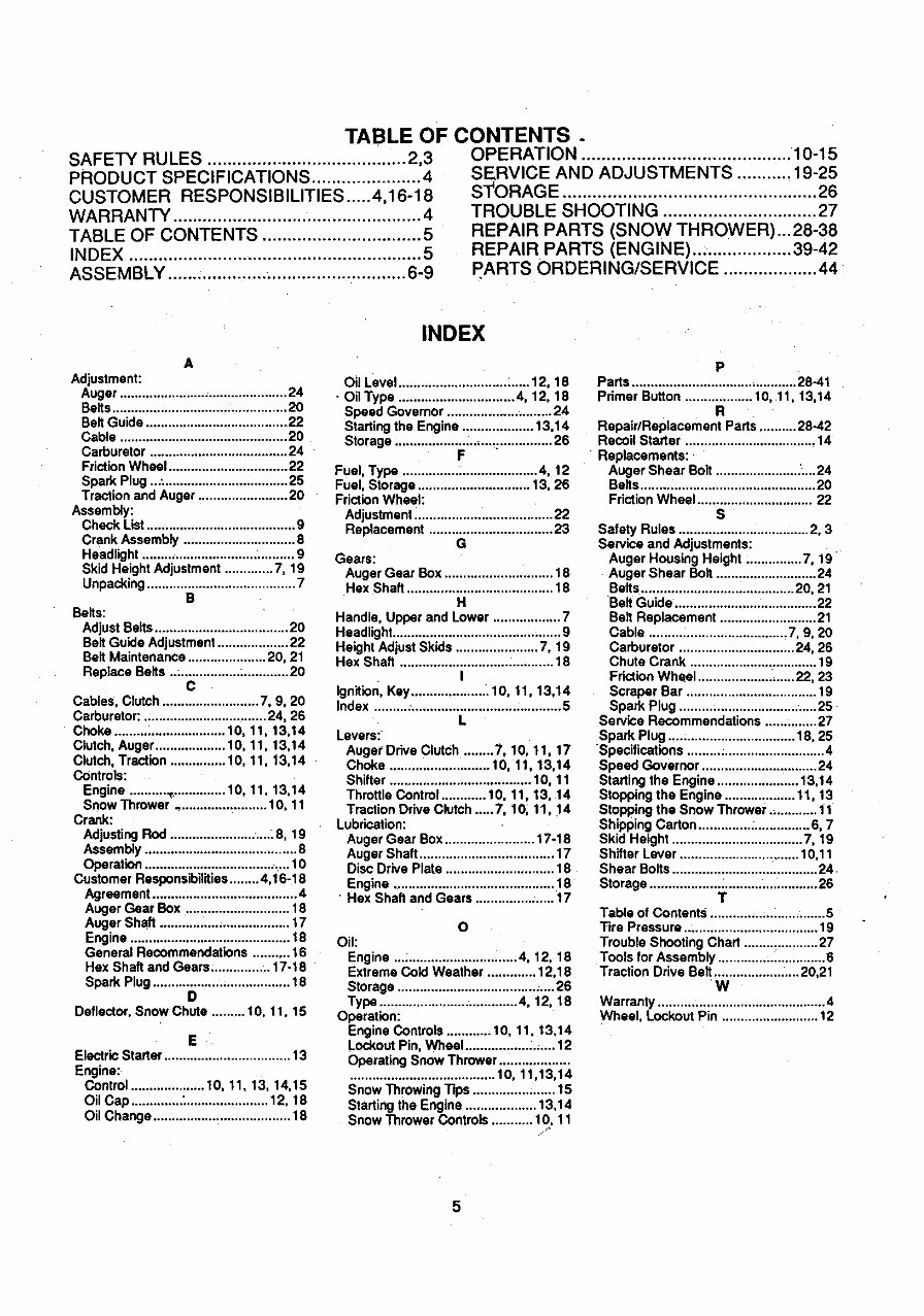
TABLE OF CONTENTS.
SAFETY RU LES ........................................ 2,3
PRODUCT SPECIFICATIONS ...................... 4
CUSTOMER RESPONSIBILITIES ..... 4,16-18
WARRANTY ................................................. 4
TABLE OF CONTENTS .............................. 5
INDEX ........................................................... 5
ASSEMBLY ................................................ 6-9
OPERATION .......................................... 10-15
SERVICE AND ADJUSTMENTS ........... 19-25
S'_ORAGE ................................................... 26
TROUBLE SHOOTING ............................... 27
REPAIR PARTS CSNOW THROWER)...28-38
REPAIR PARTS (ENGINEI .................... 39-42
PARTS ORDERING/SERVICE ................... 44
A
Adjustment:
Auger ............................................. 24
Belts............................................... 20
Belt Guide ...................................... 22
Cable ............................................. 20
Carburetor ..................................... 24
FrictionWheel ................................ 22
Spark Plug ...; ................................. 25
Traction and Auger ........................ 20
Assembly:
Check List ........................................ g
Crank Assembly .............................. 8
Headlight ......................................... 9
Skid Height Adjustment ............. 7, 19
Unpacking........................................ 7
B
Belts:
Adjust Belts.................................... 20
Belt Guide Adjustment................... 22
Belt Maintenance ..................... 20, 21
Replace Belts ..;................ :............ 20
C
Cables. Clutch .......................... 7. 9, 20
Carburetor: ................................. 24, 26
Choke ......... _ .................... t0, 1t, 13,14
Clutch, Auger ................... 1O, 11, 13,14
Clutch, Traction ............... 10, 11, 13,14
Controls:
Engine .......................... 10, 11, 13,14
Snow Thrower ........................ 10. 11
Crank:
AdjustingRod ............................ 8, 19
Assembly ......................................... 8
Operation ........................................ 10
Customer Responsibilities ........ 4.16-18
Agreement ....................................... 4
Auger Gear Box ............................ 18
Auger Shaft ................................... 17
Engine ........................................... 18
General Recommendations .......... 16
Hex Shaft and Gears ................ 17-18
Spark Plug ..................................... 18
O
Deflector, Snow Chute ......... I0. t 1.15
E
Electric Starter ................................. 13
Engine:
Control .................... 10. 11, 13, 14,15
Oil CaD .............. " ...................... 12. 18
Oil Change ..................................... 18
INDEX
Oil Level ............................. L.... 12, 18
• OilType ............................... _. 12. 18
Speed Governor ............................ 24
Starting the Engine ................... 13,14
Storage ........................... : .............. 26
F
Fuel, Type .................................... 4, 12
Fuel. Storage .............................. 13, 26
Friction Wheel:
Adjustment ..................................... 22
Replacement ................................. 23
G
Gears:
Auger Gear Box ............................. 18
Hex Shaft ....................................... 18
H
Handle, Upper and Lower .................. 7
Headlight ............................................. 9
Height Adjust Skids ...................... 7. 19
Hex Shaft ......................................... 18
I
Ignition, Key..................... 10. 11, 13,14
Index ......... : ........................................ 5
L
Levers:
Auger Drive Clutch ........ 7, 10, 11, 17
Choke ........................... 10, 11, 13,14
Shifter ...................................... 10, 11
Throttle Control ............ 10, 11.13, 14
Traction Drive Clutch ..... 7, 10, 11, 14
Lubrication:
Auger Gear Box ........................ 17-18
Auger Shaft .................................... 17
Disc Drive Plate ............................. 18
Engine ........................................... 18
• Hex Shaft and Gears ............... :..... 17
O
Oil:
Engine ................................. 4, 12, 18
Extreme Cold Weather ............. 12,18
Storage ..................................... ;.._26
Type ..................................... 4.12, 18
Operation:
Engine Controls ............ 10. 11.13,14
Lockout Pin. Wheel ........................ 12
Operating Snow Thrower ...................
....................................... 10, 11.13,14
Snow Throwing Tips ...................... 15
Starting the Engine ................... 13.14
Snow Throwar Controls ........... 10.11
P
Parts ............................................ 28-41
Primer Button .................. 10, 11, 13,14
R
Repair/Replacement Parts .......... 28-42
Recoil Starter ................................... 14
Replacements:
Auger Shear Bolt ...................... .....24
Belts............................................... 20
FrictionWheel ............................... 22
S
Safety Rules ................................... 2. 3
Service and Adjustments:
Auger Housing Height ............... 7, 19
Auger Shear Bolt ........................... 24
Belts......................................... 20. 21
Belt Guide ....................... ............... 22
Belt Replacement .......................... 21
Cable ..................................... 7. g, 20
Carburetor ............................... 24, 26
Chute Crank .................................. 19
FrictionWheel .......................... 22, 23
Scraper Bar ................................... 19
Spark Plug ..................................... 25
Service Recommendations .............. 27
Spark Plug .................................. 18, 25
Specifications ..................................... 4
Speed Governor ............................... 24
Startingthe Engine ...................... 13,14
Stopping the Engine ................... 11, 13
Stopping the Snow Thrower ............. t1
Shipping Carton .............. ................ 6, 7
Skid Height ................................... 7, 19
Shifter Lever ................................ 10.11
Shear Bolts ....................................... 24
Storage ............................................. 26
T
Table of Contents ............................... 5
Tire Pressure .................................... 19
Trouble Shooting Chart .................... 27
Tools for Assembly ............................. 6
Traction Drive Belt .................. ..... 20,21
W
Warranty ............................................. 4
Wheel. Lockout Pin .......................... 12
5
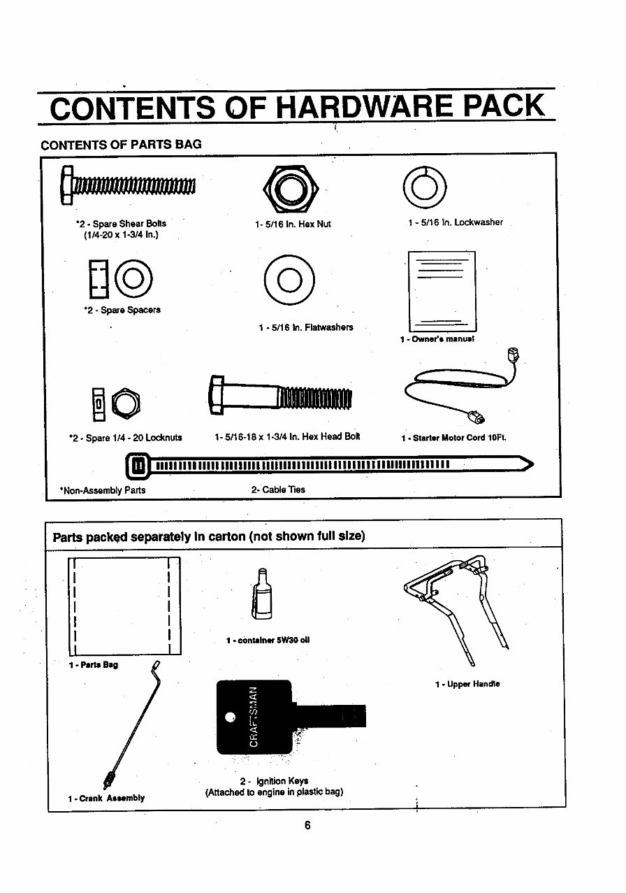
CONTENTS OF HARDWARE PACK
:ONTENTS OF PARTS BAG
"2 - Spare Shear Bolts
(1/4-20 x 1-3/4 in.)
@ ©
1- 5/16 In. Hex Nut
1 - 5/16 In. Lockwasher
H@ @
*2 - Spare Spacers
1 -5/16 In. Flatwashers
*2 - Spare 114- 20 Locknuts
*Non-Assembly Parts
1 "Owner's manual
1- 5/16-18 x 1-3/4 In. Hex Head Bolt
iiIIIIIn iiinlllllllllllllllllllllllll II IIIIIIIInlllllllllllll
2- Cable _es
1 - Starter Moto! Cord 10Ft.
>
Parts packed separately In carton (not shown full size)
I I
I
I
I
I
I
I
1-Parts _
1-Crank Assembly
1 - €ontainer5W30 oli
2- IgnitionKeys
(Attached to engine in plastic bag)
1 - Upper Handle
6
SERVICE AND ADJUSTMENTS
CAUTION: ALWAYS DISCONNECTTHE
SPARK PLUG WIRE AND TIE BACK
AWAY FROMTHE PLUG BEFORE MAK-
ING ANY ADJUSTMENTS OR REPAIRS.
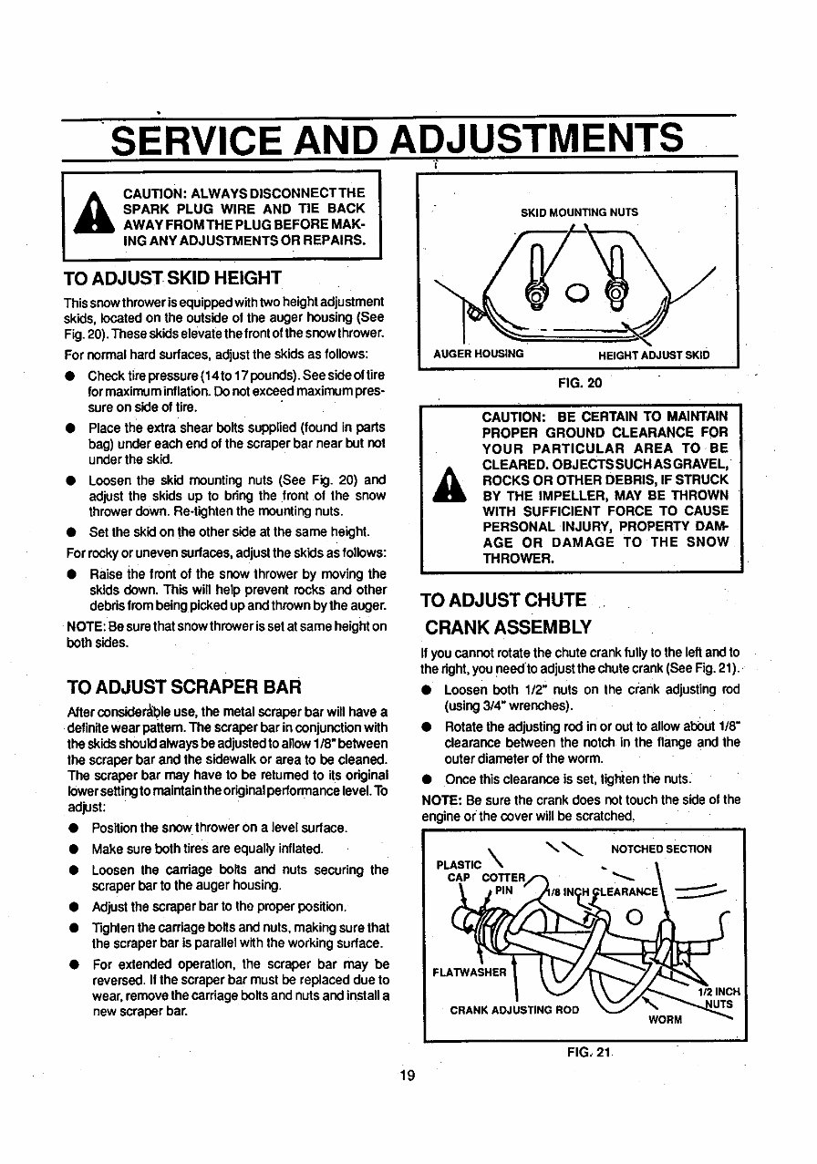
TO ADJUST SKID HEIGHT
Thissnowthroweris equippedwithtwo heightadjustment
skids,located on the outside of the auger housing(See
Fig. 20).These skidselevatethefront of thesnowthrower.
For normalhard sudaces, adjustthe skids as follows:
• Check tirepressure(14to 17 pounds).See sideoftire
for maximuminflation.Donotexceed maximumpres-
sure on side of tire.
• Place the extra shear bolts supplied (found in parts
bag) under each end of the scraperbar near but not
underthe skid.
• Loosen the skid mounting nuts (See Fig. 20) and
adjust the skids up to bring the front of the snow
throwerdown. Re-tightenthe mounting nuts.
• Set the skid on the other side at the same height.
Forrockyor uneven surfaces,adjustthe skidsas follows:
• Raise the front of the snow thrower by moving the
skids down. This will help prevent rocks and other
debrisfrom beingpickedup and thrownbythe auger.
NOTE: Be surethatsnowthrower isset at same heighton
both sides.
TOADJUSTSCRAPER BAR
After considerableuse,the metal scraper bar willhave a
definitewear pattern. The scraperbar inconjunctionwith
the skids shouldalwaysbe adjustedto allow1/8" between
the scraperbar and the sidewalkor area to be cleaned.
The scraper bar may have to be returned to its original
lowersettingtomaintaintheoriginalperformancelevel.To
adjust:
• Positionthe snowthroweron a level sudace.
• Make sure both tires are equally inflated.
• Loosen the carriage bolts and nuts securing the
scraperbar to the auger housing.
• Adjustthe scraper bar to the properposition.
• Tightenthecarriage bolts and nuts,making sure that
the scraperbar is parallelwith the workingsurface.
For extended operation, the scraper bar may be
reversed. Ifthe scraper bar must be replaced due to
wear, remove thecarriage bolts and nuts and installa
new scraperbar.
SKID MOUNTING NUTS
AUGER HOUSING
HEIGHTADJUSTSKID
FIG. 20
A
CAUTION: BE CERTAIN TO MAINTAIN
PROPER GROUND CLEARANCE FOR
YOUR PARTICULAR AREA TO BE
CLEARED. OBJECTSSUCH ASGRAVEL,
ROCKS OR OTHER DEBRIS, IF STRUCK
BY THE IMPELLER, MAY BE THROWN
WITH SUFFICIENT FORCE TO CAUSE
PERSONAL INJURY, PROPERTY DAM-
AGE OR DAMAGE TO THE SNOW
THROWER.
TO ADJUST CHUTE
CRANK ASSEMBLY
Ifyou cannot rotate the chute crankfully tothe leftand to
the dght,you need to adjustthe chutecrank (See Fig.21).
• Loosen both 1/2" nuts on the crank adjusting rod
(using3/4" wrenches).
• Rotate the adjustingrod in or out to allowabout 1/8"
clearance between the notch in the flange and the
outerdiameter of the worm.
• Once thisclearance is set, tigtltenthe nuts.
NOTE: Be sure the crank does not touchthe side of the
engine or the cover will be scratched.
_ NOTCHED SECTION
PLASTIC
CAP COTTER "_-
FLATWASHER
CRANK ADJUSTING ROD
WORM
1/2 INCH
FIG, 21
i9
SERVICE AND ADJUSTMENTS
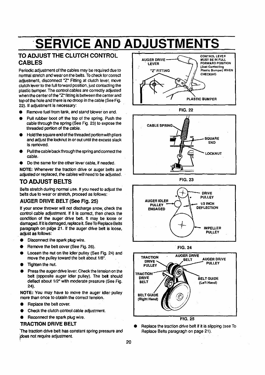
TO ADJUST THE CLUTCH CONTROL
CABLES
Periodic adjustmentof the cables may be required dueto
normalstretch and wear on the belts. Tocheckfor correct
adjustment, disconnect "Z" Fittingat clutch lever, move
clutch lever to the full forward position, just contacting the
plastic bumper. The control cables are correctly adjusted
when the center of the "Z" fitting is between the center and
top of the hole and there is no droop in the cable (See Fig.
22). If adjustment is necessary:
• Remove fuel from tank, and stand blo_'er on end.
• Pull rubber boot off the top of the spring. Push the
cable through the spring(See Fig. 23) t o expose the
threaded portionof the cable.
• Hold the squareendofthethreadedportionwithpliers
and adjust the Iocknutin or out until theexcess slack
is removed.
• PuUthecable back thmughthe spring and connect the
cable.
• Do the same for the other lever cable, if needed•
NOTE" Whenever the traction drive or auger belts are
adjusted or replaced, the cables will need to be adjusted.
TO ADJUST BELTS
Beltsstretch during normal use. If you need to adjust the
belts due to wear or stretch, proceed as follows:
AUGER DRIVE BELT (See Fig. 25)
If your snow thrower will not dischargesnow,check the
control cable adjustment. If it is correct, then check the
condition of the auger drive belt. It may be loose or
damaged. If it isdamaged, replaceit. SeeTo ReplaceBelts
paragraph on p_ge 21. If the auger drive belt is loose,
adjust as follows:
• Disconnectthe spark plugwire.
• Remove the belt cover (See Fig. 26).
• Loosen the nut on the idler pulley (See Fig. 24) and
move the pulleytoward the belt about 1/8".
• TKjhtenthe nut.
• Pressthe augerdrive lever.Check thetensionon the
belt (opposite auger idler pulley). The belt should
deflect about 1/2" with moderate pressure (See Fig.
24).
NOTE: You may have to move the auger idler.pulley
mere than once to obtain the correct tension.
• Replace the belt cover.
• Check the clutchcontrol cable adjustment.
• Reconnect the spark plug wire.
TRACTION DRIVE BELT
The tractiondrive belt has constantspringpressure and
_doesnot require adjustment.
2O
• .UGEn 0.,VE .
' LEVER _'_ _1 FORWARDPOSITION
.T _ (Just Contacting
"Z"FITTING / ,_ PlaslicBumper)WHEN
| "I- P ,,oau.PEn
FIG. 22
i
OAaLESPR,NG\ L
.__ LOCKNUT
FIG. 23
ii
_ DRIVE
_'_-,,/_ • PULLEY
AUGER DLER _ ,_
PULLEY "_ )_..._"" 1/2 INCH
ENGAGED _ i EFLECTION
_, : /"-" IMPELLER
_ PULLEY
FIG. 24
FIG. 25
• Replace the tractiondrive beltif it is slipping(see To
Replace Belts paragragh on page 21 ).
SERVICE AND ADJUSTMENTS
t
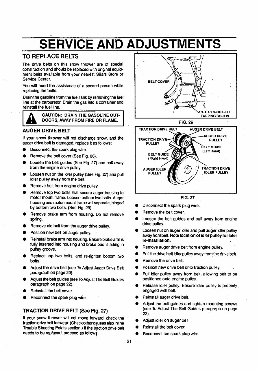
TO REPLACE BELTS \
The drive belts on this snow thrower are ot special
constructionand should be replacedwithoriginalequip-
ment belts available from your nearest Sears Store or
Service Center.
You will need the assistanceof a second person while
replacing the belts.
Drainthe gasolinefromthe fueltar¢_by removingthefuel
line atthe carburetor.Drainthe gas intoa containerand
reinstallthe fuel line.
BELT COVER /
IA CAUTION: DRAIN THE GASOLINE OUT" I
DOORS, AWAY FROM FIRE OR FLAME.
AUGER DRIVE BELT
If your snow thrower will not discharge snow, and the
auger drive belt is damaged, replace itas follows:
• Disconnectthe sparkplugwire.
• Remove thebelt cover (See Fig. 26).
• Loosen the belt guides (See Fig. 27) and puil away
from the engine drivepulley.
• Loosen nut on the idler pulley(See Fig. 27) and pull
idlerpulley away from the belt.
Remove belt from engine drivepulley.
Remove top two boltsthat secureauger housingto
motor mount frame. Loosenbottom two bolts. Auger
housingand motor mount framewillseparate,hinged
by bottom two bolts. (See Fig. 29).
• Remove brake arm from housing. Do not remove
spring.
• Remove bid belt from the auger drivepulley.
• Positionnew belt on auger pulley.
• Reinstallbrakearm intohousing.Ensurebrakearm is
fully insertedinto housingand brake pad is riding in
pulley groove.
• Replace top two bolts, and re-tighten bottom two
bolts.
• Adjustthe drive belt (see To Adjust Auger Drive Belt
paragraph on page 20).
• Adjustthe belt guides(seeTo AdjustThe BeltGuides
paragraph on page 22).
• Reinstallthe belt cover.
• Reconnect the spark plug wipe.
TRACTION DRIVE BELT (See Fig. 27)
If your snow thrower will not move forward, check the
tractionddve beltfor wear.(Checkotherc.ausesalsointhe
Trouble ShootingPointssection.)If the tractiondrivebelt
needs to be replaced,proceed as follows:
TAPPINGSCREW
FIG. 26
AUGER DRIVE BELT TRACTIONDRIVEBELT
PULLEY
PULLEY
BELTGUIDE
(Left Hand)
BELTGUIDE
(Right Hand)
AUGER IDLER TRACTION DRIVE
PULLEY IDLER PULLEY
FIG. 27
Disconnectthe spark plugwire.
Remove the belt cover,
Loosen the belt guides and pull away from engine
drive pulley.
Loosen nut on auger idler and pull auger idler pu!ley
away frombelt.Note location of Idler pulley for later
re-Installation.
Remove auger drive belt from enginepulley,
Pullthe drivebelt idlerpulley away from the drivebelt.
Remove the drive belt,
Positionnew drive belt onto tractionpulley.
Pull idler pulley away from belt, allowing belt to be
positioned onto engine pulley.
Release idler pulley. Ensure idler pulley is properly
engaged with belt.
Reinstall auger drive belt.
Adjust the belt guides and tighten mounting screws
(see To Adjust The Belt Guides paragraph on page
22).
Adjust idler on auger belt.
Reinstall the belt cover.
Reconnect the spark plug wire.
21
SERVICE AND ADJUSTMENTS
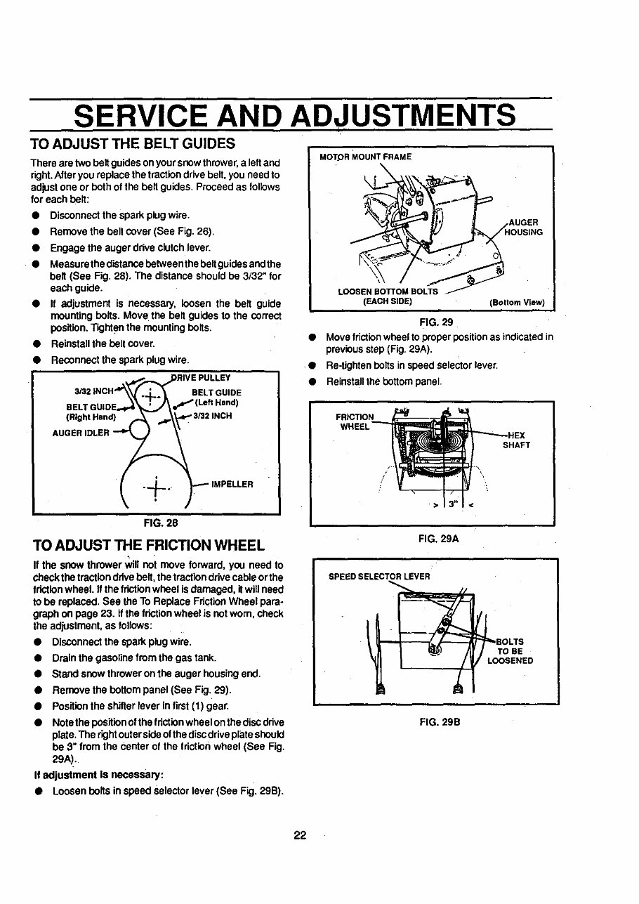
TO ADJUST THE BELT GUIDES
There are two beltguides on yoursnow thrower, a leftand
right.Afteryou replace the traction drivebelt, you need to
adjust one or both of the belt guides. Proceed as follows
for each bolt:
• Disconnectthe spark plugwire.
Remove the bolt cover (See Fig. 26).
Engage the auger drive clutchlever.
Measurethe distancebotween the beltguidesend the
belt (See Fig. 28). The distance shouldbe 3/32" for
each guide.
• If adjustment is necessary, loosen the belt guide
mounting bolts. Move the belt guides to the correct
position.Tighten the mounting bolts.
• Reinstallthe bolt cover.
• Reconnect the spark plug wire.
eEL'
(Right Hand)
BELTGUIDE
FIG. 28
TO ADJUST THE FRICTION WHEEL
If the snow thrower _11 not move forward, you need to
check the tractionddve bolt, the tractiondrivecable or the
frictionwheel. If the frictionwheel is damaged, itwill need
to be replaced, See the To Replace FdctionWheel para-
graph on page 23. If the fdctionwheel is not worn, check
the adjustment,as follows:
• Disconnectthe spark plug wire.
• Drain the gasolinefrom the gas tank.
• Stand snow thrower on the auger housingend.
• Remove the bottompanel (See Fig. 29).
• Positionthe shitterlever in first (1) gear.
Note the positionof the fdctionwheelon thediscdrive
plate, The dghtouterside ofthe discdriveplateshould
be 3" from the center of the tdction wheel (See Fig.
29A).
If adjustment is necessary:
• Loosen bolts in speed selector lever (See Fig. 29B).
MOTOR MOUNT FRAME
LOOSEN BO'R'OM BOLTS .
(EACH SIDE) (Bottom View)
FIG. 29
• Move frictionwheel toproperpositionas indicatedin
previousstep (Fig.29A).
• Re-tightenbolts in speed selector lever.
• Reinstallthe bottompanel.
FRICTION
SHAFT
/
FIG. 29A
SPEED SELECTOR LEVER
FIG. 29B
22
SERVICE AND ADJUSTMENTS
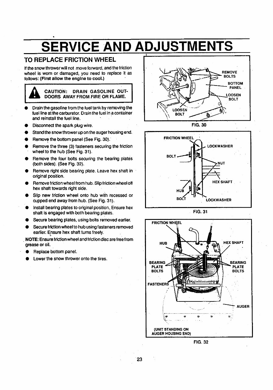
TO REPLACE FRICTION WHEEL
If the snowthrower willnot move torward,and the friction
wheel is worn or damaged, you need to replace it as
follows:(First allow the engine to cool.)
• Drainthe gasolinefrom the luel tank by removingthe
fuel lineat the carburetor.Drain the fuel in a container
and reinstallthe fuel line.
• Disconnectthe spark plugwire.
• Standthe snowthrowerup onthe augerhousingend.
• Remove the bottompanel (See Fig. 30).
• Remove the three (3) fasteners securingthe friction
wheel to the hub (See Fig. 31).
• Remove the four bolts securing the bearing plates
(both sides). (See Fig. 32).
• Remove rightside bearing plate. Leave hox shaft in
originalposition.
• Removefrictionwheelfrom hub. Slipfrictionwheelofl
hex shaft towards right side.
• Slip new friction wheel onto hub with recessed or
cupped end away from hub. (See Fig. 31).
• Installhearing plates to originalposition.Ensure hex
shaft is engaged with both bearing plates.
• Secure bearing plates, usingbolts removed earlier.
• Secure frictionwheel to hubusingfasteners removed
earlier.Ensure hex shaftturns freely.
• NOTE: Ensurefriction wheel and friction discare treefrom
grease or oil.
• Replace bottom panel
• Lower the snow thrower onto the tires.
BE. OVE
=_ _ BOTTOM
' PANEL
LOOSEN
BOLT
FIG. 30
FRICTION WHEEL "
SOLT.1"i
BOLT
LOCKWASHER
HEX SHAFT
LOCKWASHER
FIG. 31
FRICTION WHEEL
\
\
HUB
HEX SHAFT
/
BEARING
PLATE
BOLTS
BEARING
BOLTS
FASTENERS
-"'--"-AUGER
(UNITSTANDING ON
AUGER HOUSING END)
FIG. 32
23
You're Reading a Preview
What's Included?
Fast Download Speeds
Online & Offline Access
Access PDF Contents & Bookmarks
Full Search Facility
Print one or all pages of your manual
$31.99
Viewed 36 Times Today


Secure transaction
What's Included?
Fast Download Speeds
Online & Offline Access
Access PDF Contents & Bookmarks
Full Search Facility
Print one or all pages of your manual
$31.99
The Craftsman Snowblower Manual provides essential information for the assembly, operation, customer responsibilities, service and adjustments, and repair parts. This manual is valuable for both professional mechanics and DIY enthusiasts. It is available in .PDF format, offering comprehensive guidance for maintaining and repairing Craftsman snowblowers.


