

Service
and
Repair Manual
Service Manual
INTRODUCTION
This service manual has been compiled to give HOWARD Dealers and their
staff, a sequence of operations to enable the servicing and repair of a
HOWARD GEM ROTAVATOR to be carried out quickly and effectively.
Because of our policy of continuous improvement, this manual should
always be used in conjunction with the latest service bulletins covering the
GEM. These service bulletins are distributed to all HOWARD horticultural
dealers when they are first printed, and back issues are available from us on
request. HOWARD GElVl service bulletins after bulletin H.63, should be
kept with this manual, and a note added to the index of each section
affected, so that an up to date record of modifications is kept.
At the start of each section, there is a list of ordinary workshop tools that
will be required when carrying out the repairs covered by that section.
Some 'special tools' may also be required, of which a complete list can be
found under 'special tools' section 'A'.
In addition to the special tools and equipment used during some repairs, a
hydraulic or hand operated fly press (of the type found in most workshops)
will be required when removing and fitting oilseals and bearings.
Before assembly of component parts, remove dirt and grease and, in the
case of new parts, remove the special rust inhibitor, otherwise the function
of the component may be restricted when in operation. When ordering
spare parts, DO NOT confuse the illustration numbers used in this manual
with the TRUE part numbers found in the official parts list, form number
L.693.
While every effort is made to ensure that the information contained within
this manual is correct, any errors which may occur, should be brought to
the attention of our Service Department.
SECTION
Specifications, torque loadings, special tools. A
Engine removal, clutch, clutch shaft, air cleaner. B
Gearbox, wheels and hubs. C
Controls. D
Main frame, handlebars, shields. E
Rotor, rotor clutch, drive chain, backplate. F
Lubrication, maintenance and fault finding. G
PAGE
3
7
19
37
4 5
5 1
6 1
Although this manual refers to machines in current production, reference
is made, where possible, to the history of the various assemblies and
components.
ILLUSTRATION REFERENCE
The figures in brackets after component names refer to the illustration
number of the component, within thediagram specified by that instruction.
e.g. (C25-35) is Section 'C' illustration '25' illustrated component
35-Reverse idler gear.
Howard Gem
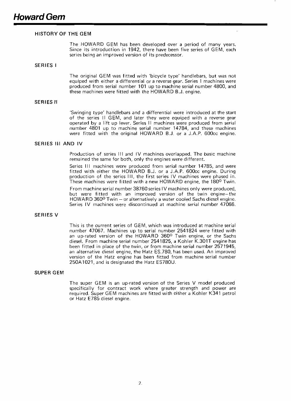
HISTORY OF THE GEM
The HOWARD GEM has been developed over a period of many years.
Since its introduction in 1942, there have been five series of GEM, each
series being an improved version of its predecessor.
SERIES I
The original GEM was fitted with 'bicycle type' handlebars, but was not
equiped with either a differential or a reverse gear. Series 1 machines were
produced from serial number 101 up t o machine serial number 4800, and
these machines were fitted with the HOWARD B.J. engine.
SERIES ll
'Swinging type' handlebars and a differential were introduced at the start
of the series II GEM, and later they were equiped with a reverse gear
operated by a lift up lever. Series II machines were produced from serial
number 4801 up to machine serial number 14784, and these machines
were fitted with the original HOWARD B.J. or a J.A.P. 600cc engine.
SERIES Ill AND IV
Production of series I II and IV machines overlapped. The basic machine
remained the same for both, only the engines were different.
Series I l l machines were produced from serial number 14785, and were
fitted with either the HOWARD B.J. or a J.A.P. 600cc engine. During
production of the series I II, the first series IV machines were phased in.
These machines were fitted with a new HOWARD engine, the 180° Twin.
From machine serial number 38760 series l V machines only were produced,
but were fitted with an improved version of the twin engine-the
HOWARD 360° Twin -or alternatively a water cooled Sachs diesel engine.
Series IV machines were discontinued at machine serial number 47066.
SERIES V
This is the current series of GEM, which was introduced at machine serial
number 47067. Machines up to serial number 2541824 were fitted with
an up-rated version of the HOWARD 360° Twin engine, or the Sachs
diesel. From machine serial number 2541825, a Kohler K.301T engine has
been fitted in place of the twin, or from machine serial number 2571945,
an alternative diesel engine, the Hatz ES.780, has been used. An improved
version of the Hatz engine has been fitted from machine serial number
250A1021, and is designated the Hatz ES780U.
SUPER GEM
The super GEM is an up-rated version of the Series V model produced
specifically for contract work where greater strength and power are
required. Super GEM machines are fitted with either a Kohler K341 petrol
or Hatz E785 diesel engine.
Section A - Srpecifications
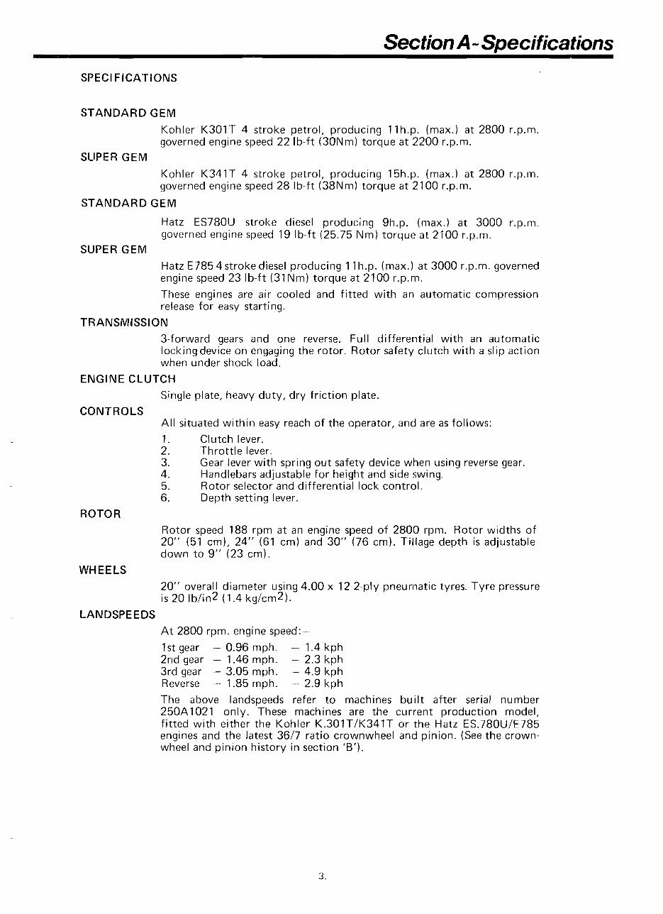
SPEC1FICATIONS
STANDARD GEM
Kohler K301T 4 stroke petrol, producing 11h.p. (rnax.) at 2800 r.p.m.
governed engine speed 22 Ib-ft (30Nm) torque at 2200 r.p.m.
SLIPER GEM
Kohler K341T 4 stroke petrol, producing 15h.p. (rnax.) at 2800 r.p.rn.
governed engine speed 28 Ib-ft (38Nrn) torque at 2100 r.p.rn.
STANDARD GEM
Hatz ES780U stroke diesel producing 9h.p. (max.) at 3000 r.p.m.
governed engine speed 19 Ib-ft (25.75 Nm) torque at 2100 r.p.m.
SUPER GEM
Hatz E785 4 stroke diesel producing 1 'I h.p. (rnax.) at 3000 r.p.m. governed
engine speed 23 Ib-ft (31Nm) torque at 2100 r.p.rn.
These engines are air cooled and fitted with an automatic compression
release for easy starting.
TRANSiVllSSlON
3-forward gears and one reverse. Full differential with an automatic
locking device on engaging the rotor. Rotor safety clutch with a slip action
when under shock load.
ENGINE CLUTCH
Single plate, heavy duty, dry friction plate.
CONTROLS
All situated within easy reach of the operator, and are as follows:
1. Clutch lever.
2. Throttle lever.
3. Gear lever with spring out safety device when using reverse gear.
4. Handlebars adjustable for height and side swing.
5. Rotor selector and differential lock control.
6. Depth setting lever.
ROTOR
Rotor speed 188 rpm at an engine speed of 2800 rprn. Rotor widths of
20" (51 em), 24" (61 cm) and 30" (76 cm). Tillage depth is adjustable
down to 9" (23 crn).
WHEELS
20" overall diameter using 4.00 x 12 2-ply pneumatic tyres. Tyre pressure
is 20 1blin2(1.4 kg/cm2).
LANDSPEEDS
At 2800 rprn. engine speed:--
1st gear - 0.96 mph. - 1.4 kph
2nd gear - 1.46 mph. - 2.3 kph
3rd gear - 3.05 mph. - 4.9 kph
Reverse - 1.85 rnph. - 2.9 kph
The above landspeeds refer to machines built after serial number
250A1021 only. These machines are the current production model,
fitted with either the Kohler K.301TIK341T or the Hatz ES.780UIE785
engines and the latest 3617 ratio crownwheel and pinion. (See the crown-
wheel and pinion history in section 'B').
Section A - Specifications
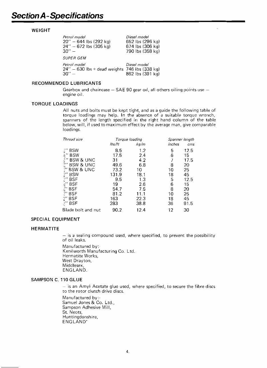
WEIGHT
Petrol model Diesel model
20" - 644 Ibs (292 kg) 652 Ibs (296 kg)
24" - 672 Ibs (305 kg) 674 Ibs (306 kg)
30" - 790 Ibs (358 kg)
SUPER GEM
Petrol model Diesel model
24" - 630 Ibs + dead weights 746 Ibs (338 kg)
30" - 862 Ibs (391 kg)
RECONlNlENDED LUBRICANTS
Gearbox and chaincase - SAE 90 gear oil, all others oiling points use -
engine oil.
TORQUE LOADINGS
All nuts and bolts must be kept tight, and as a guide the following table of
torque loadings may help. In the absence of a suitable torque wrench,
spanners of the length specified in the right hand column of the table
below, will, if used to maximum effect by the average man, give comparable
loadings.
Thread size
t" BSW
5" BSW
-
i 6
2'' BSW & UNC
g' BSW & UNC
1," BSW & UNC
2'' BSW
2" BSF
5" BSF
BSF
16
1," BSF
5" BSF
2" BSF
Blade bolt and nut
Torque loading
lbs/f t kg/m
Spanner length
inches cms
5 12.5
6 15
7 17.5
8 20
10 25
18 45
5 12.5
6 15
8 20
10 25
18 45
36 91.5
12 30
SPECIAL EQUIPMENT
HERMATITE
- is a sealing compound used, where specified, to prevent the possibility
of oil leaks.
Manufactured by :-
Kenilworth Manufacturing Co. Ltd.
Hermatite Works,
West Drayton,
Middlesex,
ENGLAND.
SAMPSON C. 110 GLUE
- is an Amyl Acetate glue used, where specified, to secure the fibre discs
to the rotor clutch drive discs.
Manufactured by :-
Samuel Jones & Co. Ltd.,
Sampson Adhesive Mill,
St. IVeots,
Huntingdonshire,
ENGLAND'
-
Section A - Special Tools
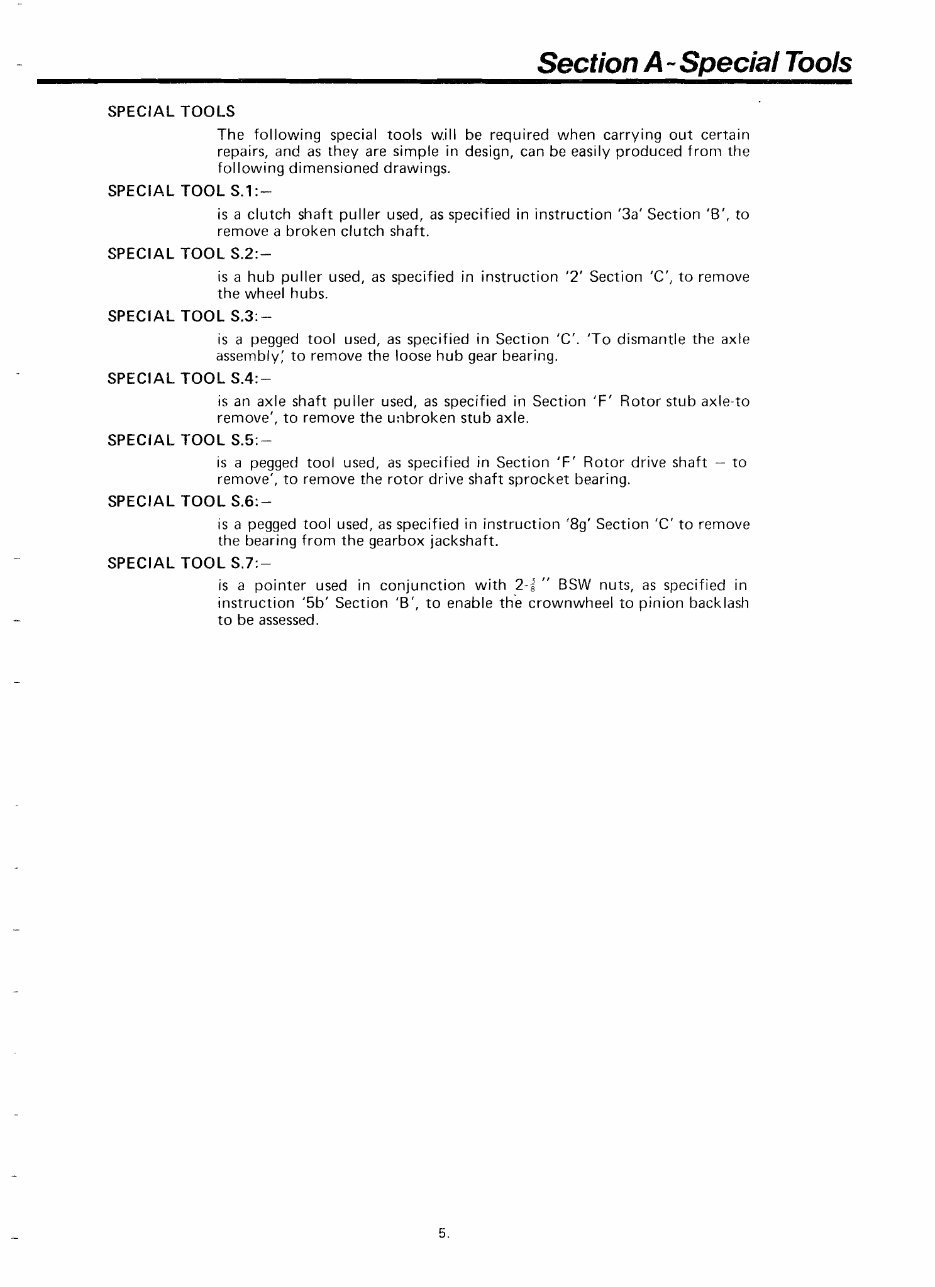
SPECIAL TOOLS
The following special tools w,ill be required when carrying out certain
repairs, and as they are simple in design, can be easily produced from the
following dimensioned drawings.
SPECIAL TOOL S.1:-
is a clutch shaft puller used, as specified in instruction '3a' Section 'B', to
remove a broken clutch shaft.
SPECIAL TOOL S.2:-
is a hub puller used, as specified in instruction '2' Section 'C', to remove
the wheel hubs.
SPECIAL TOOL S.3:-
is a pegged tool used, as specified in Section 'C'. 'To dismantle the axle
assembly: to remove the loose hub gear bearing.
SPECIAL TOOL S.4:-
is an axle shaft puller used, as specified in Section TF' Rotor stub axle-to
remove', to remove the unbroken stub axle.
SPECIAL TOOL S.5:-
is a pegged tool used, as specified in Section 'F' Rotor drive shaft - to
remove', to remove the rotor drive shaft sprocket bearing.
SPECIAL TOOL S.6:-
is a pegged tool used, as specified in instruction '89' Section 'C' to remove
the bearing from the gearbox jackshaft.
SPECIAL TOOL S.7:-
is a pointer used in conjunction with 2-2 " BSW nuts, as specified in
instruction '5b' Section 'B', to enable the crownwheel to pinion backlash
t o be assessed.
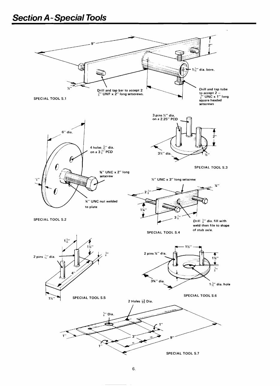
Section A - Special Tools
72
Drill and tap bar to accept 2
Drill and tap tube
' UN F x 2" long setscrews.
t o accep'
5. . .-.r.
3,
8
SPECIAL TOOL S.l
6" dia. I
%" UNC x 2"
" UNC nut welded
long
.
I L -
,- UIVL x 1" long
square headed
setscrews
SPECIAL TOOL S.3
%" UNC x 3" long setscrew
SPECIAL TOOL S.2
I
weld then file to shape
of stub axle.
SPECIAL TOOL S.4
2 pins
SPECIAL TOOL S.5
2 Holes Dia.
SPECIAL TOOL S.6
\c' SPECIAL TOOL S.7
Section B
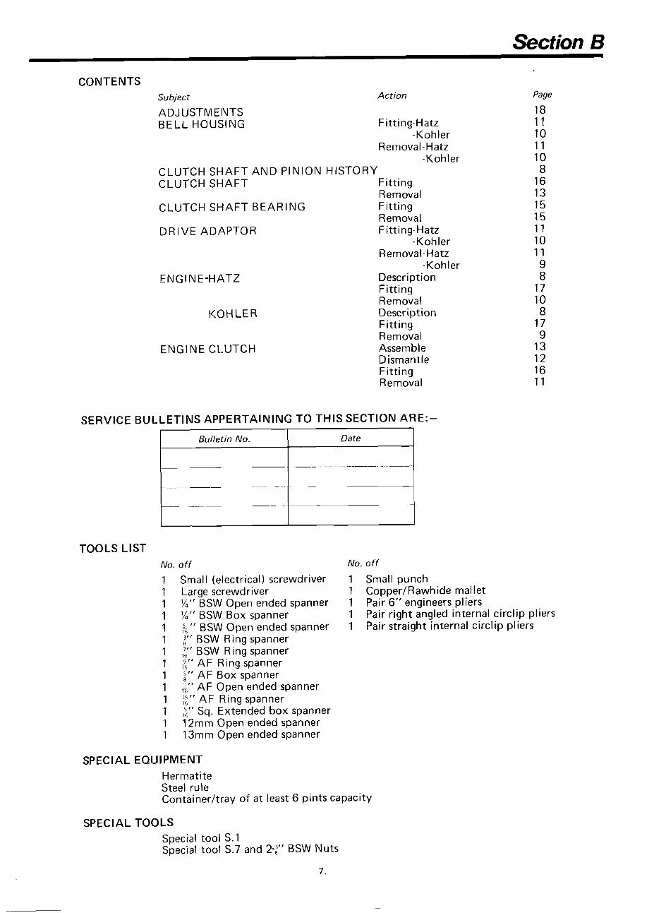
CONTENTS
Subject Action
ADJUSTMEIVTS
BELL HOUSING Fitting-Hatz
-Kohler
Removal-Hatz
-Kohler
CLUTCH SHAFT AND PINION HISTORY
CLUTCH SHAFT Fitting
Removal
CLUTCH SHAFT BEARING Fitting
Removal
DRIVE ADAPTOR Fitting-Hatz
-Kohler
Removal-Hatz
-Kohler
ENGl blE-HATZ Description
Fitting
Removal
KOHLER Description
Fitting
Removal
ENGINE CLUTCH Assemble
Dismantle
Fitting
Removal
Page
18
11
10
11
10
8
16
13
15
15
11
10
11
9
8
17
10
8
17
9
13
12
16
11
SERVICE BULLETINS APPERTAINING TO THIS SECTION ARE:-
TOOLS LIST
No. off No. off
1 Small (electrical) screwdriver 1 Small punch
1 Large screwdriver 1 CopperIRawhide mallet
1 M" BSW Open ended spanner 1 Pair 6" engineers pliers
1 M" BSW Box spanner 1 Pair right angled internal circlip pliers
1 ;" BSW Open ended spanner 1 Pair straight internal circlip pliers
1 ;" BSW Ring spanner
1 '-" BSW Ring spanner
'Z,r
AF Ring spanner
1 2"AFBoxspanner
1 g" AF Open ended spanner
1 ;" AF Ring spanner
1 ,'," Sq. Extended box spanner
1 12mm Open ended spanner
1 13mm Open ended spanner
Bulletin No.
- - - - - -
--
SPECIAL EQUIPMENT
Date
-- - -
Hermatite
Steel rule
Containerltray of at least 6 pints capacity
SPECIAL TOOLS
Special tool S. 1
Special tool S.7 and 2.;" BSW Nuts
Section B
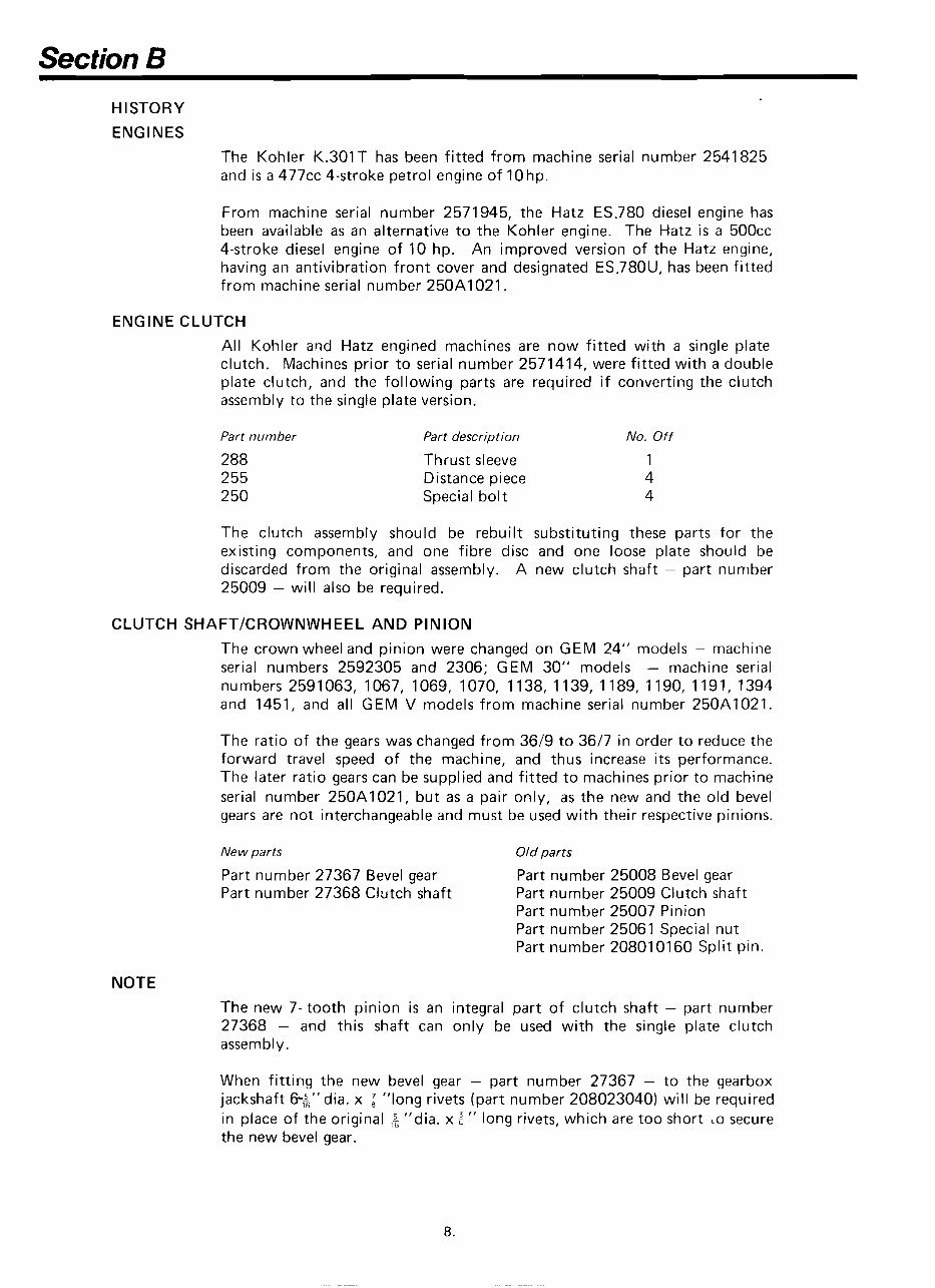
HISTORY
ENGINES
The Kohler K.301T has been fitted from machine serial number 2541 825
and is a 477cc 4-stroke petrol engine of 10hp.
From machine serial number 2571945, the Hatz ES.780 diesel engine has
been available as an alternative to the Kohler engine. The Hatz is a 500cc
4-stroke diesel engine of 10 hp. An improved version of the Hatz engine,
having an antivibration front cover and designated ES.780U, has been fitted
from machine serial number 250A1021.
ENGINE CLUTCH
All Kohler and Hatz engined machines are now fitted with a single plate
clutch. Machines prior to serial number 2571414, were fitted with a double
plate clutch, and the following parts are required if converting the clutch
assembly to the single plate version.
Part number
288
255
250
Part description
Thrust sleeve
Distance piece
Special bolt
No. Off
1
4
4
The clutch assembly should be rebuilt substituting these parts for the
existing components, and one fibre disc and one loose plate should be
discarded from the original assembly. A new clutch shaft - part number
25009 - will also be required.
CLUTCH SHAFTICROWIUWHEEL AND PINION
The crown wheel and pinion were changed on GEM 24" models - machine
serial numbers 2592305 and 2306; GEM 30" models - machine serial
numbers 2591063, 1067, 1069, 1070, 1138, 1139, 1189, 1190, 1191, 1394
and 1451, and all GEM V models from machine serial number 250A1021.
The ratio of the gears was changed from 3619 to 3617 in order to reduce the
forward travel speed of the machine, and thus increase its performance.
The later ratio gears can be supplied and fitted to machines prior to machine
serial number 250A1021, but as a pair only, as the new and the old bevel
gears are not interchangeable and must be used with their respective pinions.
New parts Old parts
Part number 27367 Bevel gear Part number 25008 Bevel gear
Part number 27368 Clutch shaft Part number 25009 Clutch shaft
Part number 25007 Pinion
Part number 25061 Special nut
Part number 208010160 Split pin.
NOTE
The new 7- tooth pinion is an integral part of clutch shaft - part number
27368 - and this shaft can only be used with the single plate clutch
assembly.
When fitting the new bevel gear - part number 27367 - to the gearbox
jackshaft 6-hr'dia. x "long rivets (part number 208023040) will be required
in place of the original ,& "dia. x a " long rivets, which are too short LO secure
the new bevel gear.
Section B
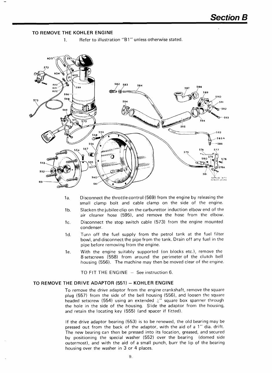
TO REMOVE THE KOHLER ElUGllVE
1. Refer to illustration "B 1 " unless otherwise stated.
la. Disconnect the throttle control (569) from the engine by releasing the
small clamp bolt and cable clamp on the side of the engine.
Ib. Slacken the jubilee clip on the carburettor induction elbow end of the
air cleaner hose (595), and remove the hose from the elbow.
Ic. Disconnect the stop switch cable (573) from the engine mounted
condenser.
Id. Turn off the fuel supply from the petrol tank at the fuel filter
bowl, and disconnect the pipe from the tank. Drain off any fuel in the
pipe before removing from the engine.
le. With the engine suitably supported (on blocks etc.), remove the
8-setscrews (558) from around the perimeter of the clutch bell
housing (556). The machine may then be moved clear of the engine.
TO FIT THE ENGl NE - See instruction 6.
TO REMOVE THE DRIVE ADAPTOR (551)'- KOHLER ENGINE
To remove the drive adaptor from the engine crankshaft, remove the square
plug (557) from the side of the bell housing (556), and loosen the square
headed setscrew (554) using an extended k" square box spanner through
the hole in the side of the housing. Slide the adaptor from the housing,
and retain the locating key (555) (and spacer if fitted).
If the drive adaptor bearing (553) is to be renewed, the old bearing may be
pressed out from the back of the adaptor, with the aid of a 1" dia. drift.
The new bearing can then be pressed into its location, greased, and secured
by positioning the special washer (552) over the bearing (domed side
outermost), and with the aid of a small punch, burr the lip of the bearing
housing over the washer in 3 or 4 places.
You're Reading a Preview
What's Included?
Fast Download Speeds
Online & Offline Access
Access PDF Contents & Bookmarks
Full Search Facility
Print one or all pages of your manual
$33.99
Howard Gem Rotavator Workshop Service Repair Manual
Viewed 78 Times Today

What's Included?
Fast Download Speeds
Online & Offline Access
Access PDF Contents & Bookmarks
Full Search Facility
Print one or all pages of your manual
$33.99

Secure transaction
What's Included?
Fast Download Speeds
Online & Offline Access
Access PDF Contents & Bookmarks
Full Search Facility
Print one or all pages of your manual
Description
The Howard Gem Rotavator Workshop Service Repair Manual is a comprehensive resource for anyone involved in the maintenance and repair of this equipment. It contains detailed information on the Kohler and Hatz engines, providing essential guidance for both professional mechanics and DIY enthusiasts.
This full workshop manual is an invaluable tool for understanding the intricacies of the Howard Gem Rotavator, ensuring that all maintenance and repair tasks are carried out with precision and accuracy.


