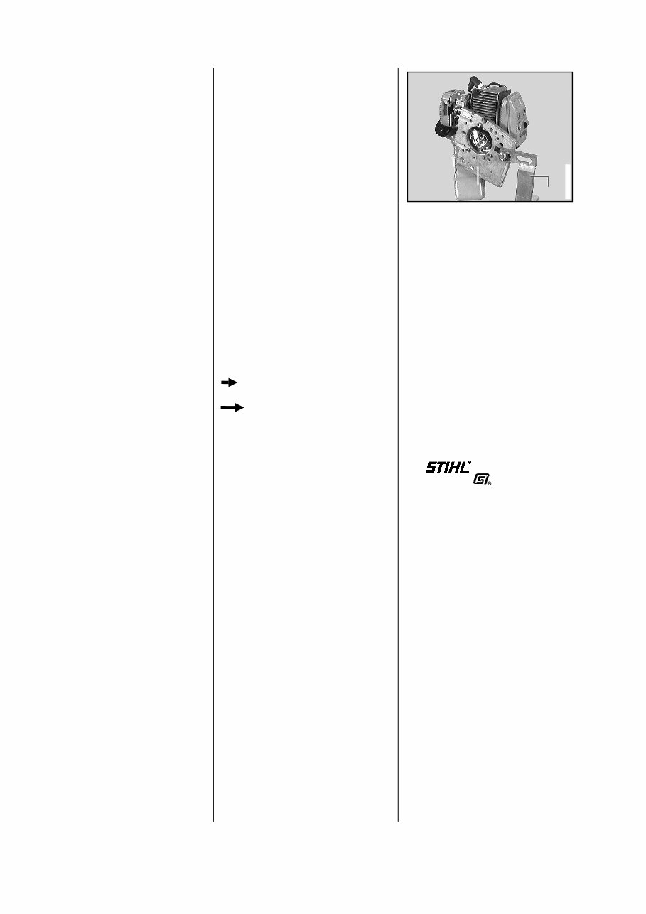
This Repair Manual contains a detailed description of all the typi- cal repair work required for these series of power tools. Repairs to be undertaken on stan- dard parts and assemblies which are used in several STIHL power tool series are described in sepa- rate repair manuals. Attention is drawn to these instruc- tions at the relevant points in this manual. Since the brushcutters FS 75, FS 80, FS 85, FC 75 and the hedge trimmer HL 75 are almost identical, the descriptions and ser- vicing procedures in this manual generally apply to all five models. Differences are described in detail. The illustrated spare parts lists should also be consulted when car- rying out repairs, for they show the installed position and sequence of assembly for the individual parts. The latest edition of the respective parts lists should always be used when determining the part num- bers of the required replacement parts. Microfilms are more up-to- date than printed spare parts lists! Faults in the machine may be due to several causes. Note the "Summary of faults" for all function groups in the manual "Troubleshooting, standard repairs". Note the "Technical Information" sheets, for they describe technical changes implemented after publi- cation of this Repair Manual. The Technical Information sheets supp- lement the parts list until a new edi- tion is published. The special tools mentioned in the text are listed in the last chapter of this manual. The tools can also be identified in the manual of "STIHL tools" on the basis of their part number. The manual lists all the tools supp- lied by STIHL. The following graphic symbols are used in the text and illustrations in order to make this manual easier to use and understand: In the text: • = Activity to be carried out; corresponds to the activity in the picture above the text. -= Activity to be carried out, but is not shown in the picture above the text. In the illustrations: - = Short arrow indicating: Note - = Long arrow indicating: Go to Repair Manuals and Technical In- formation sheets should always be on hand wherever repairs are car- ried out. They must not be passed on to third parties. Repairs can be carried out more easily by mounting the power unit on the assembly stand (2) 5910 890 3100 with the clamping plate (1) 5910 890 2100. The power unit can then be swivel- led into the most suitable working position, leaving both hands free for the work itself. Secured with M5 x 30 screws after disassembling the protective tube, shroud, starter cover and remo- ving the fuel tank. Always use original STIHL replace- ment parts. Original STIHL parts can be iden- tified by the STIHL part number, the logo and the STIHL parts symbol . The symbol may appear alone on small parts. 1. Introduction 1 1 2 2 392RA001 VA 2
2.1 Engine STIHL single-cylinder two-stroke engine with special impregnated cylinder bore Displacement: 25.4 ccm Bore: 34 mm Piston stroke: 28 mm Power output to ISO 8893: 0.9 kW (1.2 HP) at 8000 rpm Max. permissible engine speed without cutting blades (cut-off speed): 10500 rpm ( + 000 rpm) Max. speed of the output shaft (nominal value, gear head): 8500 rpm (FS 75, FC 75) 7500 rpm (FS 80, 85) Idle speed: 2800 rpm Bearings: Heavy-duty deep groove ball bearings for crankshaft; needle cages on small and big ends Big end diameter: 8 mm Conrod length: 52.5 mm Rewind starter: ElastoStart Pawls: Single pawl system Reserve pull on rope rotor: At least turn Starter rope: Dia. 3.0 mm, 800 mm long Clutch: Centrifugal clutch without linings Diameter: 66.5 mm Clutch engages at: 3700 rpm Crankcase leakage test at gauge pressure: 0.5 bar under vacuum: 0.5 bar 2.2 Fuel system Carburetor: Diaphragm carburetor with one or two adjusting screws Standard setting for carburetors with two adjusting screws High speed adjusting screw H: Back off approx. 1 turn Low speed adjusting screw L: Back off approx. 1 turn (standard setting) Carburetor leakage test at gauge pressure: 0.8 bar Function of tank vent at gauge pressure: 0.5 bar under vacuum: 0.1 bar Fuel tank capacity: 0.44 l (440 ccm) Octane number: At least 90 RON Fuel mixture: Regular brandname petrol Brandname two-stroke engine oil Mix ratio: 1:50 when using STIHL 1:50 two-stroke engine oil 1:25 when using all other brand- name two-stroke engine oils Air filter: Foam and felt elements 2. Specifications 3
2.3 Ignition system Type: Transistorized (breakerless) magneto ignition with integrated ballast Air gap: 0.2 ... 0.5 mm Ignition timing: 1.55 ... 2.25 mm before TDC at n = 8000 rpm Spark plug (suppressed): Bosch WSR 6F, NGK BPMR 7 A or Champion RCJ 6Y Electrode gap: 0.5 mm Spark plug thread: M14 x 1.25 Length of thread: 9.5 mm 2.4 Gearbox * Type: Helical-toothed bevel gears Gear ratio: 1.4 ** 1.24 *** Bearing: Deep groove ball bearing Lubrication: STIHL gear lubricant * FS 75 only has a bearing housing ** FS 80, 85 *** FC 75 4
2.5 Cutting attachment * FS 75 FS 80 FS 85 FC 75 STIHL "Supercut 10-1" mowing head STIHL "Supercut 20-2" STIHL "Supercut 20-2" mowing head mowing head STIHL "Autocut 11-2" mowing head STIHL "Autocut 21-2" STIHL "Autocut 30-2" mowing head mowing head STIHL "Autocut 30-2" STIHL "Polymatic 30-2" mowing head mowing head STIHL "Polymatic 30-2" STIHL "Polymatic 30-2" mowing head mowing head STIHL "Polycut 10-3" mowing head STIHL "Polycut 20-3" STIHL "Polycut 20-3" mowing head mowing head Grass cutting blade Grass cutting blade 230-4 ** 230-4 ** Grass cutting blade Grass cutting blade 230-8 ** 230-8 ** Brush knife 250-3 ** Circular saw blade 200 *** (scratcher-tooth) Circular saw blade 200 *** (chisel-tooth) Blade * Some cutting attachments may not be available in some countries on account of the different conditions prevailing in each country. ** Only approved for brushcutters with cowhorn handle or looped handle with U-bar, together with the guard 4119 713 4500. *** Only approved for brushcutters with cowhorn handle. 5
2.6 Special accessories 2.6.1 For the user Safety harness Safety goggles Bar scabbard for metal cutting tools STIHL multi-purpose grease (80 g tube) 0781 120 1109 STIHL gear lubricant (80 g tube) 0781 120 1117 2.6.2 For service Carburetor parts kit for Walbro carburetor WT 447 4133 007 1060 Carburetor parts kit for Zama carburetor C1Q-S28A 4227 007 1060 Gasket panel (DIN A3) 0457 281 4003 6
2.7 Tightening torques DG and P-type (Plastoform) screws are used in thermoplastic and alloyed materials. These screws cut a thread in the material when they are screwed in for the first time. The material is permanently deformed. The screws can be removed and refitted as often as desired. The strength of the screw connection is not impaired if the spe- cified tightening torque is maintained. It is therefore essential to use a torque wrench. Fastener Thread For component Tightening torque Remarks size (Nm) Spline screw IS-M5x25 Crankcase 9.5 Spline screw IS-M5x25 Spacer flange/cylinder 5.5 1) Spline screw IS-DG 5x24 Cylinder/crankcase 9.5 Spline screw IS-M5x16 Muffler/cylinder 9.5 Spline screw IS-M5x16 Muffler/crankcase 9.5 Spline screw IS-M5x16 Tensioner/spacer flange 3.5 Spline screw IS-M5x16 Fan housing/crankcase 5.5 Spline screw IS-M5x16 Starter/crankcase 5.5 Spline screw IS-M4x20 Ignition module/cylinder 4.5 Spline screw IS-M5x16 Shroud/fan housing 3.5 Spline screw IS-M5x16 Shroud/starter cover 3.5 M8 Clutch 21.0 M8 Starter carrier 20.0 M14x1.25 Spark plug 20.0 Plastoform screw IS-P5.5x12 Rope rotor in starter cover 3.5 Spline screw IS-M5x16 AV sleeve (clamping screw) 5.5 Spline screw IS-DG5x12 AV sleeve/protective tube 2.5 Nut M5 Filter housing/carburetor 4.0 Spline screw IS-M5x18 Clamping collar/bearing housing 6.5 2) Self-tapping screw IS-B3.5x9.5 Bearing housing/protective tube 3.0 2) Spline screw IS-M5x33 Clamping collar/guard 4.5 2) Stud bolt Detent spring/slide control 1.0 Spline screw IS-M5x16 Control handle, clamping collar/ protective tube (looped handle) 3.5 2) Spline screw IS-M6x50 Looped handle/protective tube 3.5 2) 4) Spline screw IS-DG5x16 Looped handle/handle hose 2.5 2) 4) Spline screw IS-M6x25 Bracket, looped handle/protective tube 4.5 3) Spline screw IS-M4x19 Control handle/handle mouldings (looped handle) 1.0 Spline screw IS-M5x16 Control handle, clamping collars/ protective tube 3.5 Plastoform screw IS-P6x14 Line limiter blade/guard 2.5 2) Spline screw IS-DG5x24 Gear housing/protective tube 9.0 3) Spline screw IS-M6x20 Gear housing/protective tube 7.5 4) Screw plug M11x10 Gearbox 10.0 7
Fastener Thread For component Tightening torque Remarks size (Nm) Spline screw IS-M5x18 Deflector shield 4.3 3) Lock nut M10x1L Cutting tool 25.0 3) Plastoform screw IS-P4x16 Control handle/handle mouldings (cowhorn) 1.0 3) Spline screw IS-M5x30 Control handle (cowhorn) 2.0 3) Spline screw IS-M6x35 Clamp, tensioner/ protective tube 4.5 3) Spline screw IS-DG5x12 Clamp/guard 5.5 4) Spline screw IS-DG5x12 Apron/guard 5.5 1) 4) Spline screw IS-DG6x25 Guard/gear housing/ tensioner 7.5 4) Lock nut M8x1.25L Blade 25.0 4) Bearing bolt IS-M10x63 Wheel/guard 19.0 1) 4) Nuts, bolts M4 All others 2.5 Nuts, bolts M5 All others 4.5 Spline screw IS-M4x16 Gearbox cover/gear housing 3.5 5) Spline screw IS-M5x20 Blade guide/gear housing 9.5 5) Spline screw IS-M5x20 Gearbox/gear housing 9.5 5) Nut M5 Blade 9.5 5) Screw plug M11x10 Gearbox cover 5.5 5) When inserting the DG and P-type screws in an existing thread: – Insert the DG or P-type screw in the hole and turn it anticlockwise until it gently drops into the hole in axial direction. – Turn screw in clockwise and tighten with the specified torque, This ensures that the screw engages the existing thread and does not cut a new thread, thus preserving the strength of the screw connection, 1) With washer 2) FS 75 3) FS 80, 85 4) FC 75 5) HL 75 Note: Screwdriver speed when working in plastic: Plastoform screws max. 600 rpm, DG screws max. 500 rpm. 8
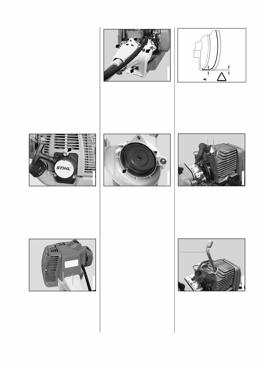
Refer to manual "Troubleshooting, standard repairs" for troubleshoo- ting procedures.. • Remove screw on starter cover. • Remove screw (1) on fan housing. - Lift off shroud (2). • Remove screws. - Pull off fan housing with protec- tive tube and set it aside. • Examine clutch drum: it must not be scored or show signs of ex- cessive wear. Important! The remaining wall thickness must be measured if the inside diameter is distinctly worn. A new clutch drum must be fitted - see 11.4 - if the wall thickness has declined to less than 80% of the original value. • Disconnect spark plug terminal (1). • Remove spark plug (2). • Insert the locking strip (1) 0000 893 5903 in the cylinder. 3. Clutch 3.1 Disassembly 1 1 2 2 392RA003 VA 392RA006 VA 1 1 392RA008 VA 392RA004 VA 80% 100% 145RA006 ! VA 1 1 2 2 392RA007 VA 392RA002 VA 9
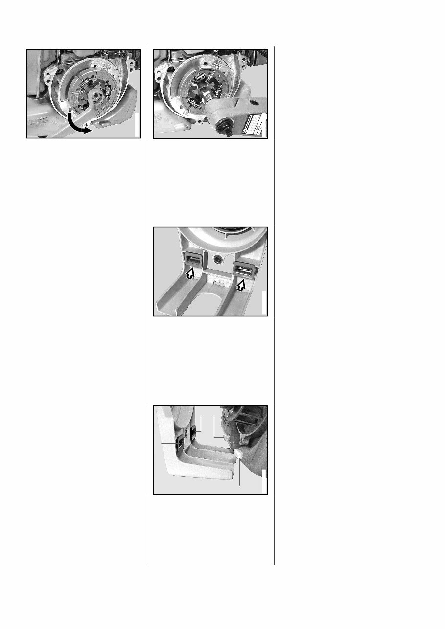
• Unscrew clutch from crankshaft stub, turning it in the direction of the arrow. - Disassemble and reassemble clutch, see manual "Trouble- shooting, standard repairs". • Screw clutch onto crankshaft with the smaller hexagon facing outwards and torque down to 21 Nm. • Ensure that inlays are present in fan housing; insert them if necessary. • Position motor on fan housing, ensuring that stubs (1) engage in inlays (2). - Insert screws in fan housing and torque down to 5.5 Nm. - Remove locking strip from cylinder. - Screw in spark plug and torque down to 20 Nm. Important! Check that the separa- te connecting nut is securely loca- ted on the screw thread of spark plugs with separate nut and tighten the nut if necessary. - Reconnect spark plug terminal to spark plug. - Fit shroud. 392RA010 VA 392RA009 VA 392RA011 VA 1 1 1 1 2 2 2 2 392RA012 VA 3.2 Installation 10
This is a comprehensive factory service repair workshop manual for the Stihl FS 75, FS 80, FS 85 Brushcutters. The manual contains easy-to-read text sections with high-quality diagrams and instructions, making it suitable for both do-it-yourself enthusiasts and experienced mechanics. It provides step-by-step instructions and highly detailed exploded pictures and diagrams to assist in completing the required job correctly and efficiently.
The Stihl FS 75, FS 80, FS 85 Brushcutters Service Repair Workshop Manual covers every single detail of the machine, including:
Introduction
Specifications
Clutch
Engine
Ignition System
Rewind Starter
Throttle Control
Fuel System
Av System
Shaft
Cutting Tool Drive
Cutting Device
Special Service Tool And Aids
And More......
File Format: PDF
Compatible: All Versions of Windows & Mac
Language: English
Requirements: Adobe Reader & Win
All pages are printable, allowing you to save money on postage and packaging. It is a valuable resource to have for maintaining your vehicle.