Ford 2100 2110 3100 4100 4110 4140 4200 Tractor Service Repair Shop Manual - IMPROVED -
What's Included?
Lifetime Access
Fast Download Speeds
Online & Offline Access
Access PDF Contents & Bookmarks
Full Search Facility
Print one or all pages of your manual
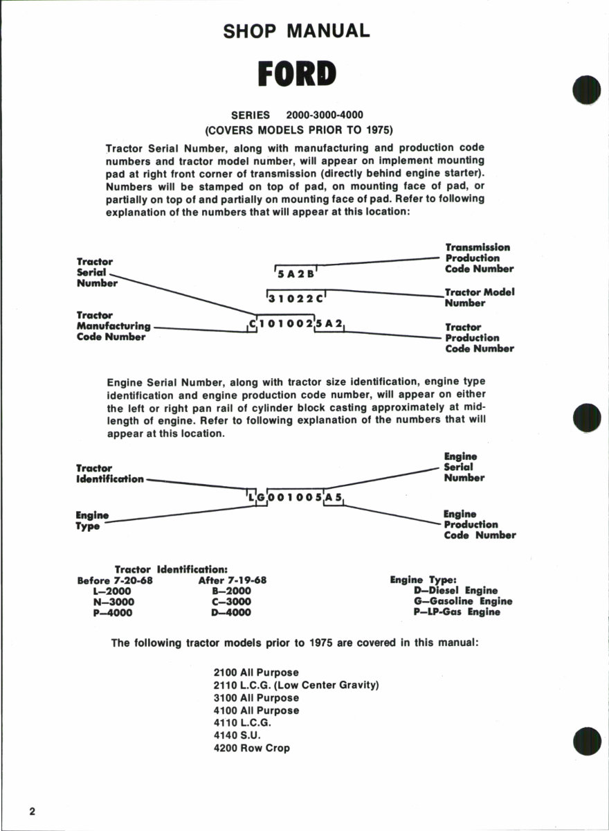
2 SHOP MANUAL FORD SERIES 2000-3000-4000 (COVERS MODELS PRIOR TO 1975) Tractor Serial Number, along with manufacturing and production code numbers and tractor model number, will appear on implement mounting pad at right front corner of transmission (directly behind engine starter). Numbers will be stamped on top of pad, on mounting face of pad, or partially on top of and partially on mounting face of pad. Refer to following explanation of the numbers that will appear at this location: Tractor Serial Number Transmission r----_-------- Production j 5 A 2 BI Code Number Model Number Tractor Manufacturing -- ____ 1 0 1 00 2'L.. S_ A_2 LI _______ Tractor Code Number Production Code Number Engine Serial Number, along with tractor size identification, engine type identification and engine production code number, will appear on either the left or right pan rail of cylinder block casting approximately at mid- length of engine. Refer to following explanation of the numbers that will appear at this location. Tractor Identification - ______ _ ___ ------------------ Type - Tractor Identification: Before 7·20·68 After 7·19·68 L-2000 8-2000 N-3000 C-3000 P-4000 1)-4000 Engine Type: D-Dlesel Engine G-Gasollne Engine P-LP-Gas Engine The following tractor models prior to 1975 are covered In this manual: 2100 All Purpose 2110 L.C.G. (Low Center Gravity) 3100 All Purpose 4100 All Purpose 4110 L.C.G. 4140 S.U. 4200 Row Crop
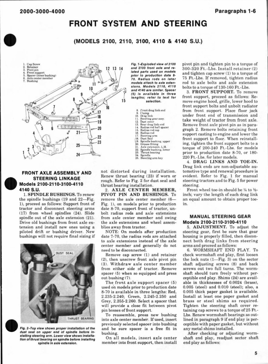
2000-3000 -4000 Paragr aphs 1-6 FRONT SYSTEM AND STEERING (MODELS 2100, 2110, 3100, 4110 & 4140 S.U.) I C .pSe ... ... 2. Ret.I ... . 3 , Pi OOlpin 4 ,,,OftU,,pport 6. s,.r.r (; n .... buoh;nl ) t . .... 1 . .. n tot . .... "'boor 1 a..oh; nl FRONT AXLE ASSEMBLY AND STEERING LINKAGE Modell 2100-2110·3100·4110 4140 S. U. 1. SP I NDLE BUSHI NGS. To renew the spindle bus hings (19 and 22- Fig. 1), proceed 8S follows: Support front of tractor and disconnect stee ring arms (17) from wheel spindles (24). Slide spindle out of t he axle extension (21). Drive old bushings from front axle ex- tens ion snd in sta ll new ones u8i ng a piloted drift or bushing driver. New bush ings will not require final sil:ing if Fifl . 2- Top III0WI pTope, 1"11.,,.tlon of Ille elull ... , on upp" end 01 .plndl. "lor. I,,· • 'llIIng,r •• rlnll"m. lo .... r vi, .... ho .... In.' ,",_ lion of"m/,/ o .. ,lng on Iplndl. b,'ore/"I'elllni fpJndl. 'n u/' ,It,n,'on , Fig. I-E.plod.d vi ... 0/ 2100 ."d 3100 /ro,,' •• ,• • "d ,... '.'.d p.rt. u •• d on mod.l. prlo, 10 produe lion d.' • • - 10. R.dlill ,odl 0" 1.,., mod.' •• 1I.elllo us. .rt.n- .10"' . Mod.'1 21H1. 4"0 .nd 4140.,. sl mn., . Sp.e. , 15} I. 'lI'.".bl. I" IlIr •• I.neill. ; ,.'.r 10 I• ., for IS .. I.ello". 8 /'rGn'd ... llnkend II. Cla mp 10, Dr. '1 Link II S . ... dn ••• • r ... r DuOl «IYa ' 13 Ro.or dra t link and It RadI ... ..... boUopa«r 15, Rad,w rod nop I • • Radl ... n>d 17.sc .... , .... .... 18, o.... !Ia.o1 I' , Spllldio l>\oAh; . I. \opper to O_ft '"nl 21 lu lo • • u noioft.L.H. 22 s..".dlobuolun .. _e r U 1\.",_ -."n. 1M Spo, •• II. 26 , !Jtao,';n. omo key n ot di sto rted durin g in s taJlation . Renew thrust bearing (23) if worn or rough. Refer to Fig. 2 for dust seal and thrust bearing ins tallation . 2. AXLE CENTER MEMBER, PIVOT PIN AND BUSHINGS. To remove the ax le ce nt e r me mber ( 6- Fig. Il , on mode ls prior to production da te 8-70, support front of tractor, un - bolt radius rods and axle exte n sions from ax le center me mber and swing the a xle exte nsions and wheel assem- blies away from tractor . NOTE : On models an er production date 7· 70. t he radius rods are attached to axle extens io ns instead of the axle center member and ge nerally do not need to be disconnected . Remove cap ac rew (1) and retainer (2). t hen unscrew rront ax le pi vot pin (3). Withd r aw axle ce nter membe r rrom either side or tr actor. Remove space r (5) when 80 eq uipped and press out bushing (7 ). The front axle s upport s pacer (5) used o'n models prior to production d ate 8-70 is availab le in three lengt hs: Red, 2.235-2.240; Green, 2.245-2.250 and Grey , 2.255-2.260. Sel ect a II pacer th at will provide a close fit between pivot pin bosses orfront.upport. To reassemble. pre811 new bus hing into axle center member. rr used, inse rt previously selected ll pacer into bushing and be s ure spacer il a rree fit in bUl l hing . On all model s, i n lle rt axle ce nt er member into front s upport. then ins tall pivot pin and tig hten pin to a tor que or 300-320 Ft .-Lbs. In sta ll r etaine r (2) and tig h ten cap screw (1) to a torque or 75 Ft.-Lbs. If removed, tighten radius rod to ax le bo lts and ax le extens ion bolts to a torque or 130-160 Ft.-Lbs. 3. FRONT SUPPORT. To remove rr ont support , proceed as follows: Re - move engine hood, grille . lower hood to front s upport bo l ts an d unbolt radiator from front s upport . Pl ace fl oor jack und er front end or transm iss ion and take weight of tractor from front axle . Remove front ax le pivot pi n as in para - graph 2. Remove bolts reta i ning fr on t support cast ing to engine and lower the front su pport to fl oor. When reinlltall- ing, tighten the front s upport bolts to a torqu e of 200-240 Ft.-Lbs. r or modelll prior to production date 8-70, or 180- 220 Ft.· Lbs. for late r models. 4. DRAG LINKS AND TOE·IN. Drag l.ink ends are non-adjustable au· tomot ive type and r enewal procedure ill evident . Ref er to Fi g. I for man ual stee ring tractors and to Fig. 5 ror power stee ri ng. F ront whee l toe-in should be \4 to 'It- inch; vary the length of each drag li nk an eq ual amount to obtain proper toe· in. MANUAL STEERING GEAR Mode ls 2100-211 0- 31 00- 41 10 5. ADJUSTMENT. To adjust th e stee ring gea r, first be sure that gea r h ousing is properly filled, th en disco n- nect b oth dr ag links from stee ring ar ms and proceed as rollows: 6. WORMSHAFT END PLAY. To check worms haft end play, fi rst loosen the lock nuts O- Fig. 3) on the sector shan adjusting screws (8) and back screws out two rull turn s. The worm- s haft should turn rreely wit hout per- ceptible end pl ay. Shims (24) are avail- a bl e in thickneasell or 0.0024 ( brass), 0.005 (steel) and 0.010 (stee 1) ; also, a 0.005 thick paper gasket is a vailable . Instal l at leall t one paper gasket and br ass or IIteel s him s as required . Tighten the stee ring sh aft cover re- taining ca p scr ews to a to r que of25 Ft.- Lbs. Renew wormshaft bearingll all out- lined in paragra ph 9 ir end pl ay i ll per- ceptible with paper gasket, but without any metaill h ims installed . After checking or adjusting worm- sh aft end play, readjust sector shaft end play a ll fo llows: 5
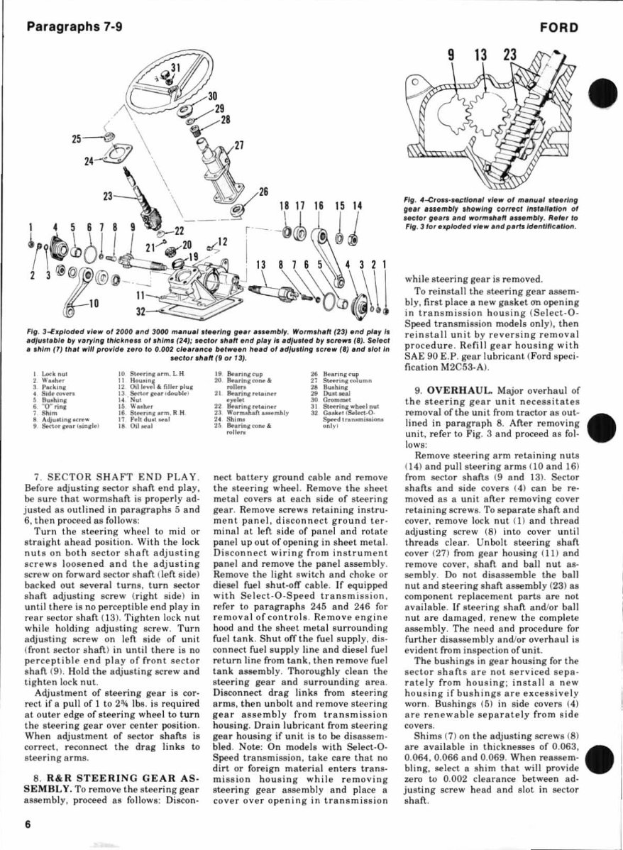
Paragr aphs 7-9 FIe. fl.w of 2000 .nd :)000 m.IIII./II"rln" If'" .... mbly. WO /m, h,ft (2J) ,nd pl.)' I. IId/u .t .",. br nryllllil'hlck" ... of .hlm. (2.): •• elor ,h.n .nd pl.)', •• d/ ... ,.d br IC,.,I'I ('). S.led •• hlm (7) ,,,,t 111'1/1 prof/d. , .ro 10 0. 002 cl,,',,/Ic. belw •• n h .. d of .d/II.II"II ,crew (') ."d ,lol'n • .etor .h.ff (t 0' Il). , Lock " 81 ... ...... ...... l.H , ........... " H ..... , p .. kinc " Oil ........ rill ... pi", • Sift ........ " $Hte'IfN."Io .. W. 1 • 8 ... hl llll .. N .. I • ""0" ri", " ....... h •• , "',. " St .. " .. , •• ", . 11 H 8 A<ij ..... i ... o< ..... " r. 1I ....... 1 , Sottorpor lo;n,lt f " 0" .... 1 7. SECTOR SHAFT END PLAY . Before adjusting sector shaft end play, be sure that wormshaft is properly ad- justed 88 outlined in para g raph s 5 and 6, then proceed as follow s: Turn t he steer ing wheel to mid or straight ah ead position. With the lock nuts on both sec tor shaft adjusting screws loosened and the adjusting screw on forward sector s haft (len side) backed out several turns , turn sector s haft adjusting screw ( right side) in unt il there is no perceptible end play in r ea r sector shan ( 13 ). Tighten lock nut while holding adjusting screw. Turn adjusting screw on len side of unit (front sector shaft ) in until there is no per cept ible end play of front sec tor sh an (9). Hold the adjusting screw and tighten lock nut . Adjust ment of steering gear is cor- rect if a pull of 1 to lbs. is required at ou ter edge of stee r ing wheel to turn t he stee ring gear over center position. Wh en adjustment of sector shafts is co rr ect, reco nnect the drag links to stee ring a rms. 8. R&R STEER I NG GEAR AS · SEMBI.. Y. To remove the stee ring gea r assembly, proceed as follows : Discon- 6 " 8oo.ri .... up K _nn't::r .. &.torin ........ " ..... " .. n -, ... " " lleari ............... " """ ... ..... , .... " GrolD-' " " SlHrin, ",_, nu' " w ........ Ci: 0_",101, " Goo ...... ls.l«t-O· .. ""- s,...I'TII ... m ........ " IInrin.«> ..... only ' rol ..... neet batte ry ground cable and remove the stee ring wheel. Remove the sheet metal covers at each side of stee ring gear. Remove screws reta ining instru- ment panel, disconnect ground ter- minal at left side of punel and rot ate panel up out of opening in sh eet metal. Di sco nnect wiring fr om instrument panel and remove the panel assembl y. Remove the light switch and choke or di esel fuel shut-olT cable. If equipped with Select-O·Speed transmission , refer to paragraph s 245 and 246 for removal of controls . Re move engine hood and the sheet metal surrounding fuel tank . Shut ofT the fuel supply, di s- co nnect fuel supply line and diesel fuel return line from tank , th en remove fuel tank assembl y, Thoroughly clean th e steering gear and surro unding area . Disco nnect drag links from steering arms, then unbolt and remove steering gear 8ssembly from transmission housing. Dra in lubricant from steering gear housing if unit is to be disassem- bled. Note: On models with Select-O- Speed transmission, take care th at no dirt or foreign material enters tran s- mi ss ion housing while removing steering gear assembly and place a cover ove r ope ning in transmission F ORD Fig . • de. 0' m.nue' .'eerinll II'" 'H,ml1#y ./lo.'nll f;Orref;! /n,I,II"lon 0' ,81;10' II .... • nd WO"",,,,,, .... mblr. II'/et 10 Fig. 3 lot e1lplod,d ,Is • • nd p.rtJ /denI/IICI ,Jon . while steering gear is removed. To reinstall the stee ring gear assem- bly, first place a new gaske t an ope ning in transmi ss ion hous ing (Select.O . Speed transmission models only), then reinsta ll unit by reversing r emoval pro ce dur e. Refill gear housing with SAE 90 E.P. gear lubricant (Ford speci . fication M2 C53-AJ . 9. OVE RH AUL.. Major over haul of the stee rin g gear unit necessitates removal ofthe uni t from tractor as out- lined in para gra ph 8. Aner removing unit, ref er to Fi g. 3 and proceed as fol - low s: Rem ove steering arm retaining nuta (1 4) and pull steering arms (10 a nd 16) from sector s hafiJJ (9 and 13). Se<:tor shafts and side covers (4) can be re- moved as a unit afte r removing cover re taining screws. To separate s han and cove r, remove loc k nut ( 1) and thr ead adjusting screw ( 8) into cover until threads clear. Unbolt s teering shaft cover (27) from gear housing ( II ) and remove cover, shaft and ball nut as- semb ly . Do not disassemble the ball nut and steering sha ft asse mbly (23) 8S co mpone nt replace me nt parts are not available. If steering s han and/or ball nut are damaged , renew the complete assembly. The need and procedure for further disassembly and/or overhaul is evident from inspection of unit. The bushings in gear housing for the secto r s haft s a re not se rvi ce d sepa- r ately from h ousing; in stall a new hou si ng if bus hing s a r e excessively worn. Bus hings (5) in side covers (4) are renewable separately from side covers. Shims (7) on the adjusting screws (8) are available in thicknesses of 0.063, 0. 064,0 .066 and 0.069. When reassem· bling, select a shim that will provide zero to 0.002 clearance between ad- justing screw h ead and slot in sector shan.
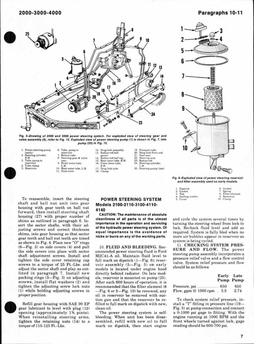
2000-3000-4000 Fig. 5-O"'II'lng 01 2000 . nd lOOO pow., .f •• rlng . p •• m. For u plod.d _le w 01 ." .ring g .. , e nd _.1_ . .... mbly (B). rei. , to Fli . 12. Explod. d "I. w of poln , .t •• r ln, pump ( I) It , how" In Fig. 7, 1.,. pump (25) In Fig . 10. I. 1'It_"HnnIPump (uri ,) 2. <H. 3. Tube, p"mp 10 ,,-rvo; , 4. 5, .... oir t. Tube.pump", ....."0" 7. .. m h.bo 8 S_ri ... ,... ..... IYe .. , 9 Frontinner tulw, CH 10. Re .. OUI .... lubo. l. H 11 OuIt ..... " To reassemble, insert the steering shaft and ba ll nu t unit i nto gea r h ousing with gear teeth on ball nut f orwa rd, then insta ll s tee ri ng shaft housing (27) with proper numbe r or sh ims as outlined in paragra ph 6. In- sert the sector shafts, wit h thei r ad· just in g screws and correct thi ckness shims, in to gea r housing 80 tha t sector gea r teeth an d ba ll nu t teet h are timed as shown in Fig. 4. Place new "0" rings ( 6- Fi g. 3) on side co vers (4) and pull the s id e covers in to place wit h sector shaft adjustment screws. Insta ll and tighten the side cover re tain ing cap screws to a to rque of 25 Ft.-Lbs. and adj ust the sector sh aft end playas out· l ined in p arag ra ph 7. I nsta ll new packing rings (3- Fig. 3) on adj us ting scr ews, i nsta ll fl at washers (2) and lighten the adjust ing screw lock nuts (1) while holding adjusti ng screws in proper position. Refill gea r housing with SAE 90 EP gear lubr icant to level wi th plug (12) opening (a pproxi mately pints). When rei n sta llin g stee ring arms, ti ght en the retai n ing nu ts (1 4) to a torque of 11 5· 125 Ft .- Lba. 12. Or_,link __ mbl)' 13 R.odl ........... .. U tdi: ........ u ... 15. Rhcout.ch. bo. il' H. 16. Yl'Ont innenu"'. 'H 17. II ... link tu'" 18 CI_ mp POWER STEERING SYSTEM Models 2100-2110-3100-4110- 4140 CAUTION : Th . malnlenance of a bl ol ut e cl .. nU n .. 1 of an pa rt l II 01 the utmolt Importl nce In tha ope ra tt on and .. rvlcl ng ol th. hydra ul ic powe r It.e rlng Iy.te m. Of .Q ua l Import a nc. I. the . ... old. nc. of nlckl or burrs on .ny of the wor ki ng parts . to. FLUID AND BLE EDI N G. Rec- ommended power steering fluid is Ford M2C41·A oil. Maintain fl uid level to full mar k on dipstick ( I-Fig . 6): reser- voir asse mb ly (5-Fig. 5) on early models is located under engine hood directly behind rad iator . On late mod· els, reservoir is mounted on pum p (25). After each 600 hours of operation, it is recommended that the filter eleme nt (8 -Fig. 6 or 3-Fi g. 10) be renewed, any oil in reservoir be removed wit h sue· tion gun and that the reser voi r be re- fi lled to fu ll ma rk on dipstick with new, clean oil. The power steeri ng system is self· bl eeding. When u nit has been disas· semb led, refill with new oi l to f ull mark on dipstick, then start engine Paragraphs 10-11 6 -<: 8 Fig. S-€. ploded " . .... 01 po ..... , .I •• cl"" res.rvol, ."d flit ., .... mbly lI.ed 0" •• , Iy ,"od.I •. I l>ipotitk 2. G .. 3 4 Se.liRI .... ...,c 5 CO .. c II. G •• ht 7 S!,!,,,, 8_ ..... "t 9 Roo"",,i, 10 Clomp and cycle the system se veral times by tu rning the s teering wheel from lock to lock. Recheck fluid level and add as required. System is fully bled when no more ai r bubblell appea r in reservoir as system is being cycled. 11. CHECKING SYSTEM PRE S· SURE AND FLOW . The power stee ring pump assembly incorpor ates a preJl.ll ure relief valve and a flow control valve. System reli ef press ure and fl ow should be as fo llows: Early Pump Pressure, psi ........... 650 Flow, gpm @ 1000 r pm . 3.5 La te Pu mp 6.0 2.74 To check system r elief pressure, in· stall a "1'" fitting in pressure li ne (19- Fi g. 5) at pu mp co nnection and connect a 0-1000 psi gage to fitting. With t he engine runn i ng at 1000 RPM and the fr ont wheels tu rned against lock, gage read ing should be 600-700 psi. 7
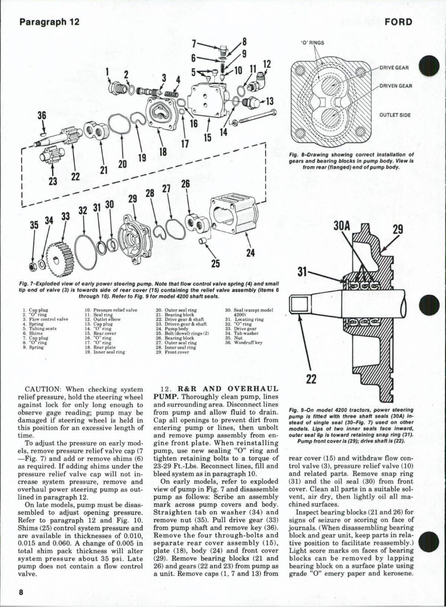
Paragraph 12 r I I I I I L.--- - - - -- -- - - - - -- - -- -- - - 9 ---"j I I I I I Fig. 7-E'tploded vl,_ of .. rly po_r ., •• ,11111 pump . HoI. Ihllllow eonlrol v,/. , ' prin" (<f) .nd ,m,II lip .nd 01 v.lve (3) I. ' ow.,d • .sd, 01 re.r cove, (15) conl.,tllng Ih. rell,' •• /. e .... mb/r (Item. 5 tll,oug" 10). R,f., to Fifl. i lor mod,' 4200 ,h.tt ... ,,. 10 J> ........ re"'l;.r .. l3. Co, pi,.. 14. "0 ""' 15. UI. -0" rin, 11. "O"';n, 18. Re .. plol" 19 Inne, ... I,;n. CA UTION: When checking system relief pressure, hol d the steeri ng wheel again st lock for only long enough to observe gage reading; pump may be damaged if stee rin g wheel is held in this position for an excessive length of time. To adjust th e pressure on early mod- els, remove pressure relief valve cap (7 - Fig. 7) and add or remove shims (6) as required. If a dding shims under the press ure relief valve cap will not in- crease system pressure, remove and overhaul power steeri ng pump as ou t.- lined in paragraph 12. On late models, pump must be disas- se mbled to adjust opening pressure . Refer to parsgraph 12 and Fig. 10. Shims (25) control system pressure and are avai lab le in thicknesses of 0.010, 0.015 and 0.060. A change of 0.005 in total shim pack thickness will alter sys tem pr ess ur e about 35 psi. La te pump does n ot contain a flow control valve. 8 12 . R&R AND OVERHAUL PUMP. Thoroughly cl ea n pump, lines and s urrounding area. Disconnect lines from pump and allow fluid to drain . Cap all openings to preve nt dirt from entering pump or lines, then un bolt and remove pump assembly from en· gine front plate . When rein s tallin g pump, use new sealing "0 " ring and tighten retaining bol ts to a torque of 23-29 Ft.· Lbs. Reconnect lines, fill and bleed system as in paragraph 10. On early models, ref er to exploded view of pump in Fig. 7 and disaasemble pump as follows: Sc ri be an assembly mark across pump co vers and body. Stra i ghten tab on was her (34 ) and remove nut (35). Pull drive gear (33) from pump shaft and remove key (36). Remov e the four through-bolts and se par ate rear cover assembly (15 ), plate (18), body (2 4) and front cover (29). Remove bearin g blocks (21 and 26) and gears (22 and 23) from pump lUI a uni t. Remove caps (1. 7 and 13) from FORD OUTlETSI Of Fig. '-Or.wlng .howlng corr.cl In.I.II.flon 01 g •• ,. .nd bfJ.rlng bloch In pump bodr. V"w I. from ,..r (".ng.d) .nd 01 pump bod,. Fig. 9-on mod., 4200 Ir.clo,., pow" .1."lng pump I. fllI.d wit" th,. • • "." ••• 1. (lOA) I". .I .. d 01 ,'ng" ••• 1 (30-I'lg. 7) 1I •• d on 01"" mod., •• Up. 01 two Inn" ••• ,. I. c. Inw.rd. Ollte, ... , lip I. tow.rd re'.'n'ngln.p ring (ll). Pllmp Ironl co ... rl. (29); drift ,h. " I, {22}. rear cover (15) and wit hdraw flow co n· tro l valve (3), pressure re li ef valve (10) and rela ted par ts. Remove snap ring (31) and the oil seal (30) from front cover. Clean all parts in a suitable sol· vent, air dry, then li ghtly oil a ll rna· chined surfaces. Inspect bearing blocks (2 1 and 26) for signs of seizure or sco ring on face of jo urnal s. (When disassembli ng bearing bl ock and gear unit, keep parts in rela· tive position to facilitate reassembly.) Light score marks on faces of bearing blocks can be removed by lapp i ng bearing bl oc k on a s urf ace plate using grade "0" emery paper and kerosene.
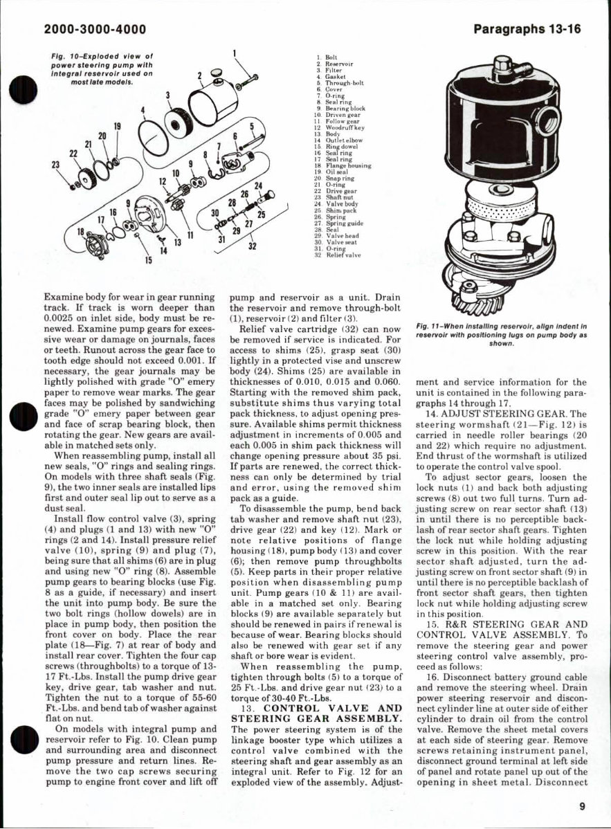
• 2000-3000-4000 Fig. lO-E.plod.d ., .... 01 1 po .... , 1I •• "lIi pump wllh "'- I BoIL Inl.gr.1 """01, III.d on 2 O? 2 R_,no< l F,It., G .. k., Th ... 8. eo •• , 20 9 I ! 7 O.rlne 8 a .. 1 nnl \I 1Io-."n,bl... k HI O" •• n, .. , II F.llu- .u, 12 WotOd,ufThy 13 1Ic>d,' H Ouol.'.lbow U II>n,,,,,wol 1$ s- rinK Il St.1 ri.., 12 24 ,. 18 Flu,," bouoinl Oil ... 1 Snip ,in, 21 O.rin, II Driy.,U' Sh.ft nul Vllft body Sh,n, patk 26. Spr/nl I( 30 21 21" 11 31 29 32 21 9,rinr ,y,dor 28. Sell 15 Examine body for wear in gear runnin g track. If track is wo rn deeper than 0.0025 on inlet side, body must be re- newed. Examine pu mp gears for exces- sive wear or damage on journals, faces or t eeth. Huno ut across the gear (ace to tooth edge should not exceed 0.001. If necessary, th e gear journa ls may be lightly polished with grade "0" emery paper to remove wear marks. The gea r faces may be polished by sand wi chin g grade "0" emery paper between gear and face of sc rap bearing block, then rotati ng the gea r. New gears are avail- able in matched sets only. When reassembling pump, install a ll new seals, " 0" rings s nd sealing rings. On models with three s haft sea ls (Fig. 9), the two inn er seals are installed lips fir st and ou ter seal lip out to serve as a dust seal. Inst all flow co ntrol valve (3), s prin g (4) and plugs (I a nd 13) with new "0" rin gs (2 and 14 ). I nstall pressure relief va lve (10 ), sp ring (9) and plug ( 7), being s ur e that all s him s (6) are in plu g and us i ng new "0" ring (8). Assemble pump gears to bea ri ng blocks (use Fig. 8 as a gtlide, if n ecessary) an d insert the unit into pump body. Be sure the two bolt. ri ngs (holl ow dowels) are in pl ace in pump body, t h en posit.ion the fron t cover on body. Place the rear plate OS- Fig. 7) at r ea r of body and insta ll rear cover. Tighten the four cap screws (throughbolts ) to a torque of 13- 17 Ft.-Lbs. In sta ll the pump drive gear key, drive gear, tab washer and nut . Tighten the nu t to a torque of 55-60 Ft.-Lha. an d bend tab of washer against nat on nut. On models with integral pump and reservoi r refer to Fig. 10. Clean pump and s urroundin g area a nd disconnect pump pressu.re and r etu rn lines. Re- move the two ca p sc r ews sec uri ng pump to engine fron t cover and lin off :l9 V.I •• h.ld 30 V.I ...... .. ly. pump a nd reservoir as a unit. Drai n th e reservo ir and remove through-bolt (0, reser voir (2) an d filter (3). Relief valve cart ridge (32) can n ow be removed if serv ice is indi ca ted. For access to s hims (25), gras p seat (30) ligh tly in a protected vise and unscrew body (24). Shims (25) are a vail able in thicknesses of 0.01 0,0.0 15 and 0.060. Starting with t he removed ah im pack, su bstit ute s him s thus varying to ta l pack thickness, to adjust opening pres- s ure . Available s him s permit th ick n ess adju stme nt in increments of 0.005 a nd eac h 0.005 in s him pack t hi ckness will change ope nin g press ure abo ut 35 psi. If pa rt s are r enewe d, the co rr ect thi ck- ness can only be determined by trial a nd erro r, u sing the r emo ved shim pack as a guide. To di !l8ssemble the pump , bend back tab washer and remove sh an nut (2 31, drive gear (22) and key (12l. Ma rk or note relative positions of n ange housing (18), pump body (1 31 and cover (6)j then remove pump through bo lts (5). Kee p parts in their proper rel ative po s ition when disassembling pump unit. Pump gears ( 10 & II ) are avail- able in a match ed set only. Bearing bl oc ks (9) are Iwaitable separately but should be renewed in pairs ifrenewal is because of wear. Bearing blocks should also be renewed with gear set if any shaft or bore wear is evident. When r eass emblin g the pump. tighten through bolts ( 5) to a torque of 25 Ft .- Lbs. and drive gea r nut 123) to a torque ofaO-40 Ft.-Lbs. 13. CONTROL VALVE AND STEER I NG GEAR ASSEMBLY. The power ste ering system is of the linkage booster type which utilizes a co ntrol valve co mbined with th e Rtee rin g sh an and gear assembly as an in tegra l unit. Refer to Fi g. 12 for an exploded view of the assem bly. Adju st. Paragraphs 13-16 FlO. f I_Wil en In. fe/lln ll ,..e,...olr. el lgn Inden lln re.e,.,olr willi po.lllonlnlllulI' on pump bodr e. . hown. ment and service informat ion for t he unit is contained in the following par a- graph s 14 thr ough 17. 14. ADJUS'I' STEERING GEA R. The steer ing worms h aft f2 1 -Fig. 12) is carried in needle roller bearings (2 0 and 22) which require no adj u st ment . End thrust of the wormshan is utilized to operate the control valve spool. To adjust sector gears, loosen th e lock nuts (I) and back bot h adjusting scre ws (8) out two full turns. Turn ad- just ing screw on rear 'sector shaft (3) in until there ia 110 percept ible ba ck- lash of rear sector sh aft gears. Tighten the lock nut while holding adjusting screw in this position. With t he rear sec tor s haft adjusted, turn the ad- ju sting screw on front sector s han (9) in until there is no perceptible backlash of front sector s han gears, then t ighte n lock nut while holding adjusting screw in this position. 15. R&R STEERING GEAR AND CON TROL VALVE ASSEMBLY. 10 remove the steerin g gear and power steering cont rol valve assembl y, pro- ceed as follows: 16. Disconnect battery ground cable and remove the steering wheel. Drain power stee ring reservo ir and discon- line at outer side of eit h er cylinder to drain oil from the control valve. Remove the sheet metal covers at each side of steering gear. Remove sc r ews retaining instrument pan el, disconn ect ground term i nal at left side of p anel a nd r otate panel up out of the opening in she et m eta l. Di sco nnect 9
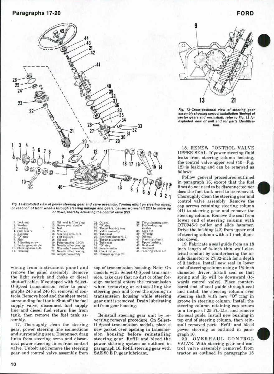
Paragraphs 17-20 I .. F ifl . J2-E.plod.d dew of pow., .' •• rl "" 11" " .nd w eI., .... rn!:>I'. rum lnl/ . ffort on ., .. ,Ini' 11'11 •• /, or , •• cllon of fronl wh •• I. Ih rougll, ' •• rln jf Ilnt.g •• nd g •• ,. , c.u ••• wor m.h.N (21) /0 mo" lip Or down, th.r.b, .c lu.llnll' II ,. COlllrol w.'" (21), , Lock nul " Oil r ,lIe.,I". 2. ", .. her " 50<10. "or. double 3. """kin. ". Nul 4 Sidu" ..... ". W •• he r S. B ... hl ... ". SIHri n lum. R H 6. " 0" lin, ". f ell dUM .ul 7. ShIm " Oil ... 1 8 A<tiu.Un ......... " Pipe .... hl 10 006 1 It SKtor ".r .• in,l. .. . 10 s. ... rin. um, I- H ". WtH-nuha n ._mbly " Hou.inr n ... lI •• !>t.rinr " Ad.pteu_mbly wiring fr om in s trum e nt panel and remove the panel assembly. Remove the lig ht s wit ch and choke or diesel shut-off cable. If equipped with Select· O-Speed transmissio n, refer to para· graphs 245 and 246 fo r removal of con· trois. Remove hood and the sheet metal s urrounding fue l tank . Shut off the fu el supply valve, disco nnect fu el supply line and diesel fuel return li ne from tank , the n remove the fuel tank as· sembly. 17. Thoroughly clean the stee ring gear, power s teering line connections and sur rounding area. Disconnect drag links from steering arms and discon· nect power s teer ing lines from control valve. Unbolt and remove the steering gear and control valve assem bl y from 10 24. 0,1_1 ,. Th, .... bnring'.Y " Pr.·loood .prin. 26. Tkruot 1ri"ll'''Y' ..... her 27 ,. Lock au' 28. Tube .. " " "0 ' . 29 R<. .riion pl1On .... 121 " 011 :;;r 30. Thnootpl........ UI) .. 31. Tube .. " " UppOr bu,hinlr 32. "0" , i"ll" ., 0 ",,_, 33. !W'ur n II nlon .. Grommet ChHk • • 1 ... .. SlNrin. "' .....1 nul " PI"n.er.prinp I31 top of transmission h ousing. Note: On mode ls wi th Select-O-Speed tran s mi s- sion, take care that no dirt or other for- eign material enters the transmission when removing or re in stalling the steer ing gear and cover the opening in transmission housing while steer ing gear unit is removed. Drain l ubricating oil from gear housing. Reinstall stee rin g gear un it by reo versing removal procedure. On Select· O·Speed transmission models, place a new gaske t over opening in transmis- sion h ous ing before reinstalling stee rin g gear. Refill and bleed t he power steeri ng system as outlined in paragraph 10. Refill steeri ng gear with SAE 90 E.P. gea r lubricant. FORD 13 21 Fig. 13--Cro .. • .. cllon.1 d._ 01 .ta.rlng ga., .... mbl' ,"owlng corract In.t.II.Uon (liming) 01 •• cto. g •• ,. Md wo.m. h, ft; . af., 10 Fig. 12 lor erpl oded vlaw 01 unit .nd f or p. rt . Id. nUflc.· lion. 18. RE NE\\- : ONTROL VALVE UP PER SEAL. If }>Ower s teering fluid leaks from steering column housing, the control valve upper seal (40---Fig. 12) is leaki ng and can be renewed as follows: Follow general procedures outlined in paragraph 16 , except that the fu el lines do not need to be disconnected nor does the fu el tank need to be removed. Thoroughly clean the s teering gear and control valve assembly. Remove the cap screws retaining steering co lumn (41) to steering gear and remove the stee r ing column . Remove t he seal from lower end of stee ri ng column with OTC945-2 puller and slide h ammer. Drive t.he bus hing (42) from upper end of steering column with a I-inch diam- eter dowe l. 19. Fabricate a seal guide from an 18 inch length of *- inch thin wall elec- trical conduit by counterboring the in- side diameter to 27/32-inch for a de pth of 3 inche s. Ins tall new seal in lower end of steering column using a 1" inch diam eter driver. in stall seal so that spr ing and lip will be downward ( to- wards cont.rol valve ). Place co unter· bored end of seal g Ui de t.hrough seal and in sta ll the steer ing co l um n over s teering sh aft wit.h new "0 " ring i.n groove in s teering co lumn . InstalJ the steering column retaining cap screws to a torque of 25 Ft.·Lbs. and remove t.he seal guide. Ins tall new bush ing in top end of stee ring column , then rein- stall removed parts. RefilI and bleed power steer ing as outlined in para- grap h 10. 20 . OVER H AU L CONTRO L VALVE. With steer ing gear and con- trol valve a ss emb ly removed from tractor as outlined in paragraphs 15
This comprehensive Ford 2000, 3000, 4000 3 Cylinder Tractors Service Repair Shop Manual provides essential instructions for maintaining and servicing your tractor. It includes detailed diagrams and manufacturer specifications.
Improved manuals feature bookmarks, searchable text, indexing, and enhanced quality.
This manual covers the following tractor models prior to 1975:
2100 All Purpose
2110 L.C.G. (Low Center Gravity)
3100 All Purpose
4100 All Purpose
4110 L.C.G.
4140 S.U.
4200 Row Crop
It contains detailed illustrations, exploded diagrams, drawings, and photos to guide you through the service repair procedures.
Navigation is made easy with convenient chapter bookmarks and the ability to search by keyword. You can print out the entire manual or specific sections.
Fully bookmarked chapters facilitate quick navigation to identify exact service repair procedures.
Contents include but are not limited to:
Auxiliary Transmission
Belt Pulley
Brakes
Carburetor
Clutch
Cooling System
Diesel Fuel System
Differential
Electrical System
Engine
Final Drive
Front Axle
Front System
Gasoline Fuel System
Governor
Hydraulic Lift System
LP Gas System
Power Steering System
Power Takeoff
Rear Axle
Remote Control Valves
Service Data
Steering
Transmission - 4-Speed
Transmission - 6-Speed
Transmission - 8-Speed
Transmission - 8-Speed - "Select-O-Speed"
And Much More...
The manual is enriched with numerous pictures, diagrams, illustrations, and charts. It provides technical details and step-by-step instructions for your convenience.
For immediate access to this manual, click the green & white button at the top right-hand side of this page.
Additional Information:
Some documents may require the newest version of Acrobat Reader to display correctly. If you encounter any issues, try upgrading to the latest version of Adobe Acrobat Reader.
If you require any other manuals, feel free to email me.
Recently Viewed
5,521,897Happy Clients
2,594,462eManuals
1,120,453Trusted Sellers
15Years in Business
Price:
Actual Price:
Ford 2100 2110 3100 4100 4110 4140 4200 Tractor Service Repair Shop Manual - IMPROVED -