

Yamaha Banshee 350 Repair Manual
What's Included?
Fast Download Speeds
Online & Offline Access
Access PDF Contents & Bookmarks
Full Search Facility
Print one or all pages of your manual

Yamaha Banshee Service Manual 1987-2006
This manual is comprised of a base manual, plus four additional supplement manuals
for the updates made to the Yamaha Banshee over the years. Use the links below or
the bookmarks to the left to get to the manual that covers your model.
1987-1989 models base manual
1990 models supplement manual
1991-1996 models supplement manual
1997-2001 models supplement manual
2002-2006 models supplement manual
OYAMAHA
LlT-11616-05-87
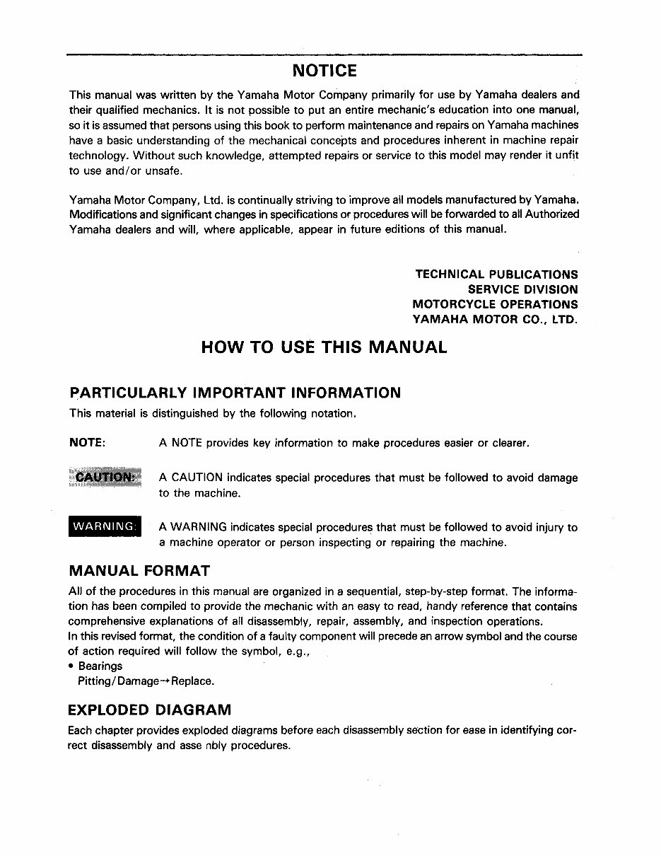
NOTICE
This manual was written by the Yamaha Motor Company primarily for use by Yamaha dealers and
their qualified mechanics. It is not possible to put an entire mechanic's education into one manual,
so it is assumed that persons using this book to perform maintenance and repairs on Yamaha machines
have a basic understanding of the mechanical concepts and procedures inherent in machine repair
technology. Without such knowledge, attempted repairs or service to this model may render it unfit
to use and/or unsafe.
Yamaha Motor Company, Ltd. is continually striving to improve all models manufactured by Yamaha.
Modifications and significant changes in specifications or procedures will be forwarded to all Authorized
Yamaha dealers and will, where applicable, appear in future editions of this manual.
TECHNICAL PUBLICATIONS
SERVICE DIVISION
MOTORCYCLE OPERATIONS
YAMAHA MOTOR CO., LTD.
HOW TO USE THIS MANUAL
PARTICULARLY IMPORTANT INFORMATION
This material is distinguished by the following notation.
NOTE:
WARNING:
A NOTE provides key information to make procedures easier or clearer.
A CAUTION indicates special procedures that must be followed to avoid damage
to the machine.
A WARNING indicates special procedures that must be followed to avoid injury to
a machine operator or person inspecting or repairing the machine.
MANUAL FORMAT
All of the procedures in this manual are organized in a sequential, step-by-step format. The informa-
tion has been compiled to provide the mechanic with an easy to read, handy reference that contains
comprehensive explanations of all disassembly, repair, assembly, and inspection operations.
In this revised format, the condition of a faulty component will precede an arrow symbol and the course
of action required will follow the symbol, e.g.,
• Bearings
Pitting / Damage -+ Replace.
EXPLODED DIAGRAM
Each chapter provides exploded diagrams before each disassembly section for ease in identifying cor-
rect disassembly and asse nbly procedures.
CD ®
1=1~1
l~g~1 §ll
@ @
IENGI~ .. I
P>oLI ~I
® ®
EAR~'I
§iAS~
(J)
®
I ELEe I 91 ~ppxl."1
@
~
®
~
\!J)
~
@
~
@
[B
'.1A'l
~
,LID
1
~§l
1
(LV
1
m Gl a
lW d~ ®
~L- ~Si'-L- ~
(ij)
1
IT!
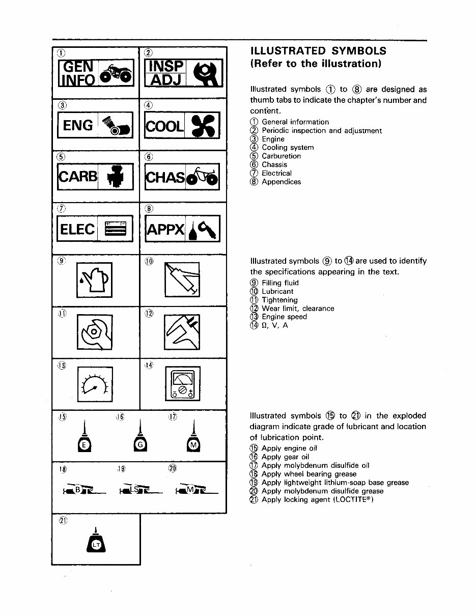
ILLUSTRATED SYMBOLS
(Refer to the illustration)
Illustrated symbols CD to ® are designed as
thumb tabs to indicate the chapter's number and
content.
CD General information
(2) Periodic inspection and adjustment
@ Engine
@ Cooling system
@ Carburetion
@ Chassis
(J) Electrical
® Appendices
Illustrated symbols ® to @ are used to identify
the specifications appearing in the text.
® Filling fluid
® Lubricant
@ Tightening
@ Wear limit, clearance
@ Engine speed
(j]) fl, V, A
Illustrated symbols ® to @ in the exploded
diagram indicate grade of lubricant and location
of lubrication point.
® Apply engine oil
® Apply gear oil
@ Apply molybdenum disulfide oil
® Apply wheel bearing grease
@ Apply lightweight lithium-soap base grease
@ Apply molybdenum disulfide grease
@ Apply locking agent (LOCTITE®)
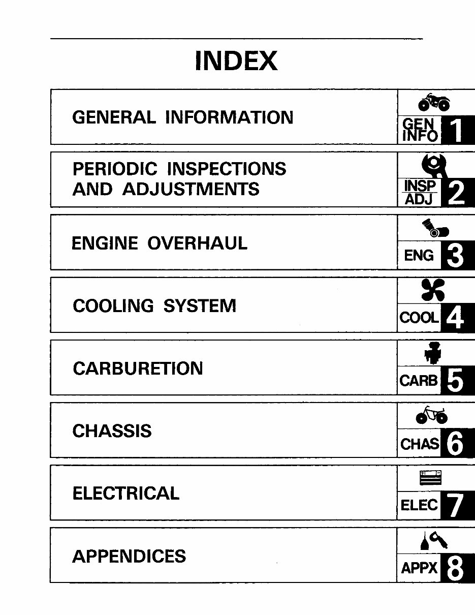
INDEX
GENERAL INFORMATIO-N
PERIODIC INSPECTIONS
AND ADJUSTMENTS
ENGINE OVERHAUL
COOLING SYSTEM
..
GEN
INFO

____________________ I~~~I~I
CHAPTER 1
GENERAL INFORMATION
MACHINE IDENTIFiCATION ...................................... . 1-1
VEHICLE IDENTIFICATION NUMBER .............................. 1-1
ENGINE SERIAL NUMBER ....................................... 1-1
IMPORTANT INFORMATION ...................................... 1~2
ALL REPLACEMENT PARTS ..................................... 1-2
GASKETS, OIL SEALS AND O-RINGS ............................. 1-2
LOCK WASHERS/PLATES AND COTTER PINS .................... 1-2
BEARINGS AND OIL SEALS ..................................... 1-2
CIRCLIPS ...................................................... : 1-3
SPECIAL TOOLS .................................................. 1-3
FOR TUNE-UP ......................................... <" •••••••• 1-3
FOR ENGINE SERVICE ........................................... 1-4
FOR CHASSIS SERVICE ......................................... 1-5
FOR ELECTRICAL COMPONENTS ................................. 1-5
u

II~~~ IAI MACHINE IDENTIFICATION
1-1
GENERAL
INFORMATION
MACHINE IDENTIFICATION
VEHICLE IDENTIFICATION NUMBER
The vehicle identification number CD is stamped
into the left side of the lower pipe.
Starting Serial Number:
JY 42G UOO* H COOO101
ENGINE SERIAL NUMBER
The engine serial number CD is stamped into the
left side of the engine.
NOTE: ________________________ _
The first three digits of these numbers are for
model identifications; the remaining digits are the
unit production number.
Starting Serial Number:
YFZ350T . ............... . 2GU-000101
NOTE: ________________________ __
Designs and specifications are subject to change
without notice.

IMPORTANT INFORMATION II~~ IAI
IMPORTANT INFORMATION
ALL REPLACEMENT PARTS
1. We recommend to use Yamaha genuine parts
for all replacements. Use oil and/or grease
recommended by Yamaha for assembly and
adjustment.
GASKETS, OIL SEALS AND a-RINGS
1. All gaskets, seals and O-rings should be
replaced when an engine is overhauled. All
gasket surfaces, oil seal lips, and O-rings must
be cleaned.
2. Properly oil all mating parts and bearings dur-
ing reassembly. Apply grease to the oil seal
lips.
LOCK WASHERS/PLATES AND COTTER
PINS
1. All lock washers/ plates CD and cotter pins
must be replaced when they are removed.
Lock tab(s) should be bent along the bolt for
nut flat(s) after the bolt or nut has been
properly tightened.
BEARINGS AND OIL SEALS
1. Install the bearing(s) CD and oil seal(s) @
with their manufacturer's marks or numbers
facing outward. (In other words, the stamped
letters must be on the side exposed to view.)
When installing oil seal(s), apply a light coat-
ing of light-weight lithium base grease to the
seal lip(s). Oil the bearings liberally when in-
stalling.
Do not use compressed air to spin the bear-
ings dry. This causes damage to the bearing
surfaces.
1-2
I ~~ IAI IMPORTANT INFORMATION/SPECIAL TOOLS
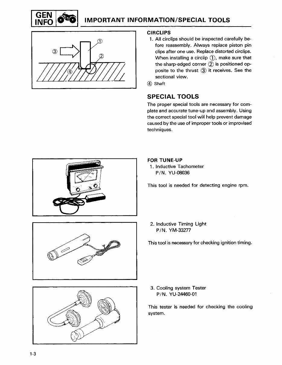
CIRCLIPS
1-3
1. All circlips should be inspected carefully be-
fore reassembly. Always replace piston pin
clips after one use. Replace distorted circlips.
When installing a circlip CD, make sure that
the sharp-edged corner @ is positioned op-
posite to the thrust @ it receives. See the
sectional view.
® Shaft
SPECIAL TOOLS
The proper special tools are necessary for com-
plete and accurate tune-up and assembly. Using
the correct special tool will help prevent damage
caused by the use of improper tools or improvised
techniques.
FOR TUNE-UP
1. Inductive Tachometer
PIN. YU-08036
This tool is needed for detecting engine rpm.
2. Inductive Timing Light
PIN. YM-33277
This tool is necessary for checking ignition timing.
3. Cooling system Tester
PIN. YU-24460-01
This tester is needed for checking the cooling
system.

SPECIAL TOOLS I ~~~ IAJ
4. Fuel Level Gauge
PIN. YM-01312
This gauge is used to measure the fuel level in
the float chamber.
FOR ENGINE SERVICE
1. Universal Clutch Holder
PIN. YM-91042
This tool is used to hold the clutch when remov-
ing or installing the clutch boss locknut.
2. Flywheel Magneto Puller
PIN. YM-Ol189
This tool is used to remove the flywheel.
3. Piston Pin Puller
PIN. YU-01304
This tool is used to remove the piston pin.
4. Rotor Holder
PIN. YU-01235
This tool is used when loosening or tightening the
flywheel magneto securing bolt.
1-4
You're Reading a Preview
What's Included?
Fast Download Speeds
Online & Offline Access
Access PDF Contents & Bookmarks
Full Search Facility
Print one or all pages of your manual
$41.99
Viewed 69 Times Today


Secure transaction
What's Included?
Fast Download Speeds
Online & Offline Access
Access PDF Contents & Bookmarks
Full Search Facility
Print one or all pages of your manual
$41.99
The Yamaha Banshee 350 Factory Service Manual for "All Years" is an invaluable resource for both professional mechanics and DIY enthusiasts. With 278 pages of comprehensive information, this manual provides detailed guidance for diagnosing and repairing your ATV. It covers a wide range of topics including:
- General Information
- Maintenance
- Engine Removal and Installation
- Engine Fuel System
- Engine Lubrication and Cooling
- Engine Combustion System
- Transmission System
- Front Wheel and Steering System
- Rear Wheel System
- Fenders and Exhaust Pipe
- Electrical System
- Troubleshooting
Whether you prefer a digital .PDF manual or a .OVA file manual, this resource offers instant access to the information you need without the wait for mail delivery. Say goodbye to the hassle of handling a paper copy manual and simply print the specific pages you require for your repair tasks.


