Contents Example of wiring diagram ................................................................... 2 Examples of symbols on wiring diagram ............................................ 3 Component wiring diagram index ........................................................ 5 Component wiring diagrams ................................................................ 7 Illustrations index LHD ........................................................................ 62 Illustrations LHD .................................................................................. 63 Illustrations index RHD ..................................................................... 102 Illustrations RHD ................................................................................ 103 Circuit card electrical centre ............................................................. 118 Fuses on circuit card electrical centre ............................................ 119 Extra fuse holders .............................................................................. 120 Relays on circuit card electrical centre ........................................... 121 Extra relays ......................................................................................... 122 Cable harness .................................................................................... 123 List of connectors .............................................................................. 128 List of components ............................................................................ 134 Abbreviations ..................................................................................... 139 Cable colour code .............................................................................. 140 Feedback 1
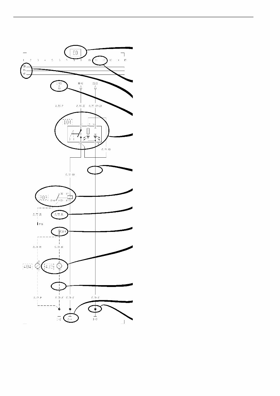
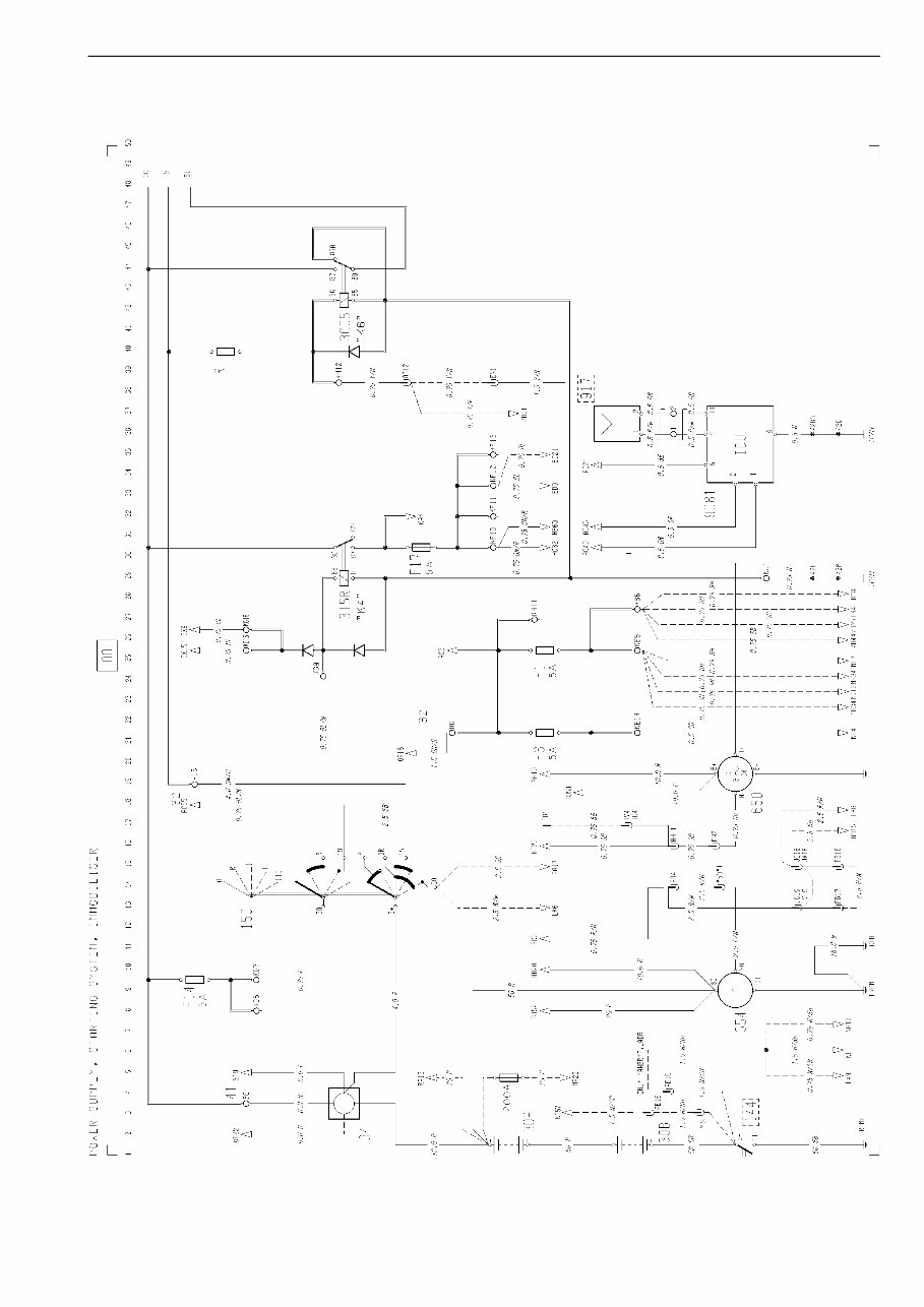
Group 37 Wiring diagram FL6 Example of wiring diagram Example of wiring diagram T3009608 Refer to the list of contents for the designation of the circuit diagram. If the circuit diagram designation is boxed in with broken lines this means that the circuit diagram is not standard on all market or vehicle models. Seek column. 30 Voltage battery, kl.30. 15 Voltage with starting key in drive position, kl.15. 61 Voltage when alternator charges, kl.61. Reference arrow (for circuit diagram EA, seek column 13). Switch, comp. no. (104). Single lines, cables. Relay, comp. no. (303). Cable area and colour (0.75 mm² blue). Connector (CLA terminal 4). Bulb, comp. no. (403) A broken line box round the component number shows that the component is not standard on all markets or vehicle models. If the line is broken this means the cable is not standard on all markets or vehicle model. Earth connection point no: 2. and earth terminal no: 4. (see diagram Earth Connections). Joint sleeve. 2
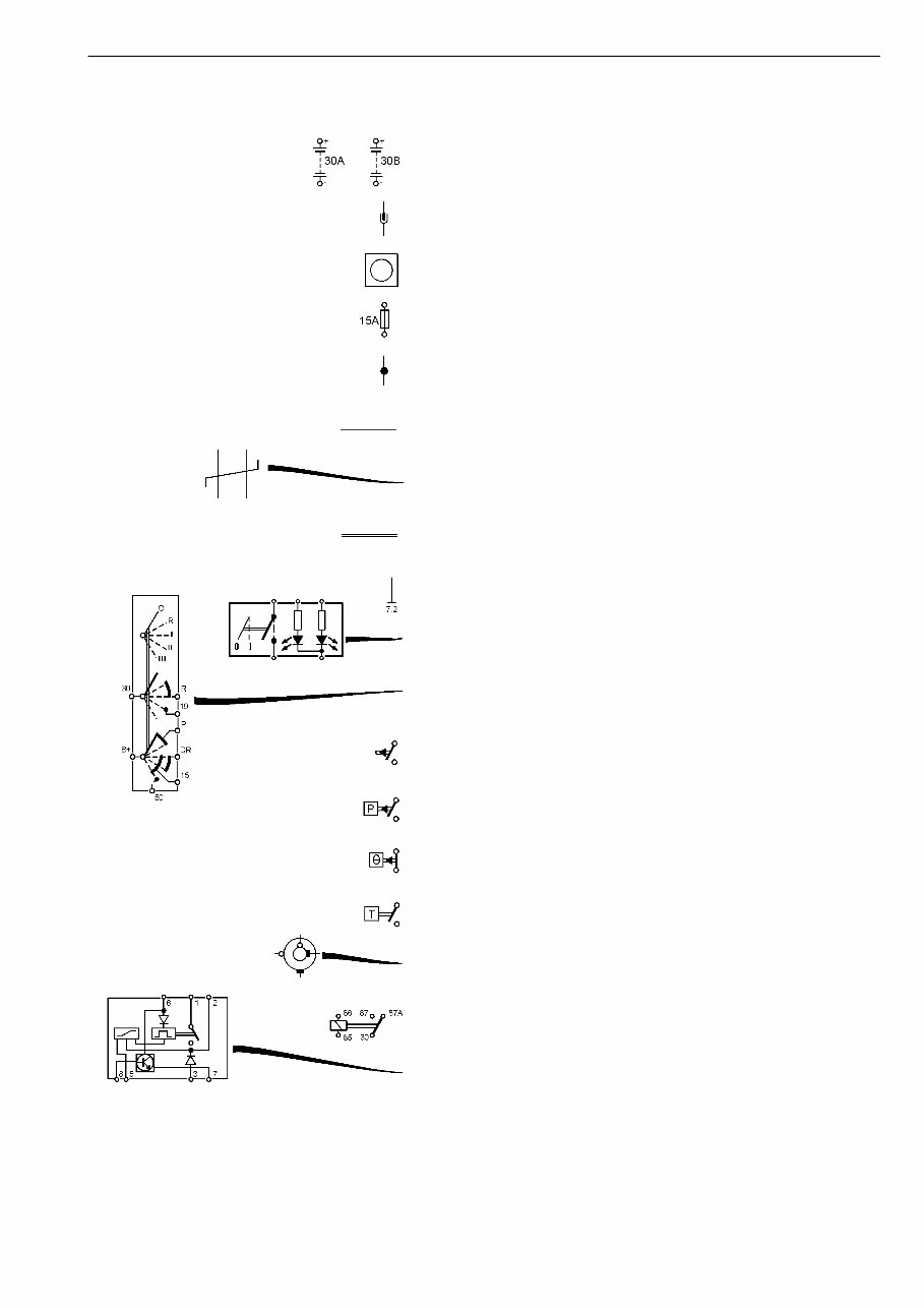
Group 37 Wiring diagram FL6 Examples of symbols on wiring diagram Examples of symbols on wiring diagram T3009609 Battery Connector Junktion Fuse Joint sleeve Cable Twisted cables Conductor on circuit card Earth connection and cable Switch Switch, starting switch Closing contakt Closing contakt, pressure-regulated Break contakt, temperature-regulated Closing contakt, time-regulated Slip contakt, horn Relay Relay with internal circuit diagram 3
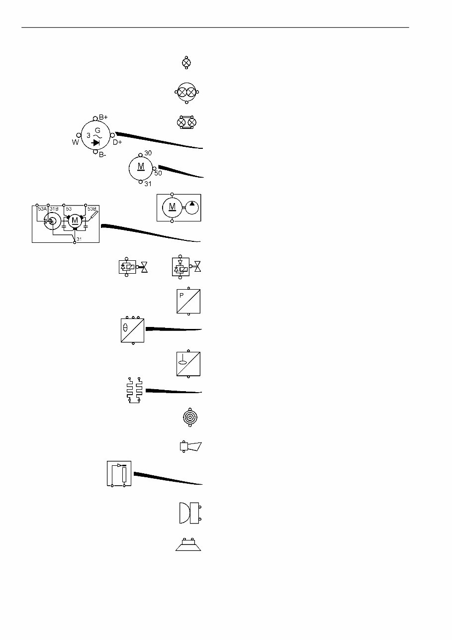
Group 37 Wiring diagram FL6 Examples of symbols on wiring diagram T3009610 Bulb Bulb, full beams and dipped beams Bulb, tail light Alternator Starter motor Washer motor Windscreen wiper motor Solenoid valve with diode Pressure sensor Temperature sensor Level sensor Starting heater Cigarette lighter Horn Rheostat Buzzer Loudspeaker 4
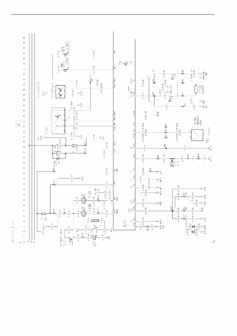
Group 37 Wiring diagram FL6 Component wiring diagram index Component wiring diagram index AA Power supply, starting system, immobiliser ..................................................................... page 7 AC Vehicle ECU ..................................................................................................................... page 8 BJ Engine ECU, DIESEL ...................................................................................................... page 10 BM Gearbox ECU, MD3060P5/MD3560P5 ........................................................................... page 12 BZ Engine ECU, CNG ........................................................................................................... page 14 CE Head light, parking light, DRL .......................................................................................... page 16 CG Fog light, rear fog light ..................................................................................................... page 17 CH Spot light ......................................................................................................................... page 17 CK Brake light ........................................................................................................................ page 18 CN Direction indicator, hazard warning light .......................................................................... page 18 EA Reversing light, reversing warning alarm ......................................................................... page 19 ED Loading light/fifth wheel light ........................................................................................... page 19 EJ Identification lamps .......................................................................................................... page 20 EN Rotating warning light ...................................................................................................... page 20 ER Interior lighting ................................................................................................................. page 20 EV Cigarette lighter ............................................................................................................... page 21 EX 12 V power supply ........................................................................................................... page 21 FA Horn ................................................................................................................................. page 21 GA Wiper, washer .................................................................................................................. page 22 HA Climate unit ...................................................................................................................... page 23 HB Cab heater, air ................................................................................................................. page 24 HC Cab and engine heater, PH-ENGCA (EBERSPÄCHER) ................................................. page 25 HD Rest heater, short stop cab heater .................................................................................. page 26 HE Electrically heated seat .................................................................................................... page 26 HG Electrically heated mirrors ............................................................................................... page 27 HH Electrically operated mirrors ............................................................................................ page 27 HM Fuel filter heater, water separator heater ......................................................................... page 28 JA Radio ............................................................................................................................... page 28 KA Electrically operated window winders .............................................................................. page 29 KE SRS, air-bag .................................................................................................................... page 30 KH Central locking CHID -B276335 ....................................................................................... page 30 KH Central locking CHID B276336- ....................................................................................... page 31 LD Power take-off or KOBLAM .............................................................................................. page 31 LE Power take-off and KOBLAM ........................................................................................... page 32 LG Differential lock ................................................................................................................ page 32 LK Automatic gearbox ........................................................................................................... page 33 5
Group 37 Wiring diagram FL6 Component wiring diagram index MA Bogie lift, A-ride ............................................................................................................... page 34 MF Air suspension, 4x2/6x2, RIGID, E-MEDIUM CHID-B344350 ......................................... page 35 MF Air suspension, 4x2/6x2, RIGID, E-MEDIUM CHID B344351– ....................................... page 36 MG Air suspension, 4x2, TRACTOR CHID-B344350 ............................................................. page 37 MG Air suspension, 4x2, TRACTOR CHID B344351– ........................................................... page 38 MH Air suspension, 4x2, RIGID, L-H MEDIUM CHID-B344350 ............................................. page 39 MH Air suspension, 4x2, RIGID, L-H MEDIUM CHID B344351– ........................................... page 40 MV Air-dump .......................................................................................................................... page 41 NA Instrument LHS module CHID-B356223 ......................................................................... page 42 NA Instrument LHS module CHID B356224– ........................................................................ page 43 NC Instrument RHS module .................................................................................................. page 44 NF Tachograph ...................................................................................................................... page 45 NZ Instrument center module ............................................................................................... page 46 OA Basic ABS, D-version ...................................................................................................... page 48 PA Headlight adjust ............................................................................................................... page 50 RA Taillift ................................................................................................................................ page 50 XA Extra fuse block, key switch relay .................................................................................... page 51 XD Extra connection body builder ......................................................................................... page 52 ZA Earth connections ............................................................................................................ page 54 ZB Earth connections CHID-B356223 .................................................................................. page 56 ZB Earth connections CHID B356224– ................................................................................ page 58 ZD ADR battery main switch, current limiter CHID-B340450 ................................................ page 60 ZD ADR battery main switch, current limiter CHID B340451– .............................................. page 61 6
The Volvo FL6 Truck Wiring Diagram Service Manual is a highly detailed manual with comprehensive service procedures and wiring diagrams. It provides step-by-step instructions, detailed illustrations, and is designed for both do-it-yourself enthusiasts and experienced mechanics. The manual covers a wide range of topics including wiring diagrams, component wiring, illustrations, fuses, relays, wiring harnesses, ground connections, connectors, wiring numbers, components, abbreviations, and more.
This manual comes in PDF format, compatible with all versions of Windows and Mac operating systems. It requires Adobe Reader and WinZip for access. With instant access upon purchase, this manual is a valuable resource for keeping your Volvo FL6 Truck in proper working condition.

")