

Volvo FH truck VTO2514B Gearbox construction Manual
What's Included?
Fast Download Speeds
Online & Offline Access
Access PDF Contents & Bookmarks
Full Search Facility
Print one or all pages of your manual
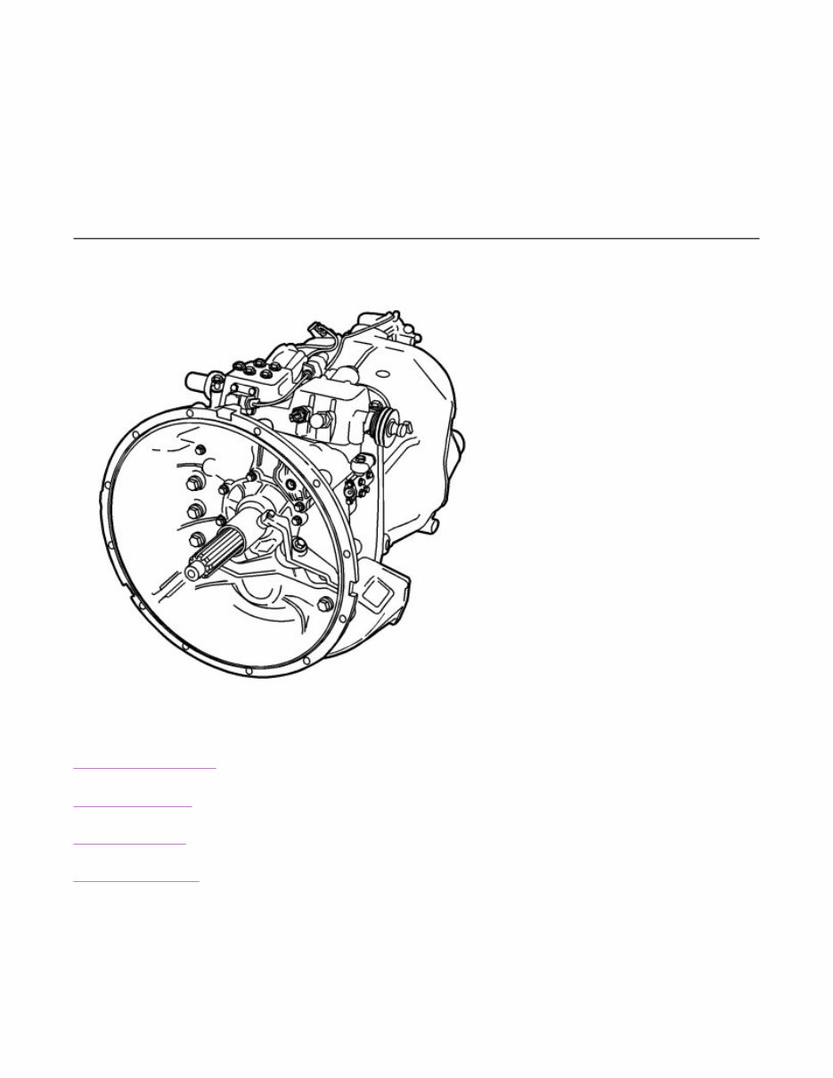
Gearbox construction
Contents
Gear selector housing
Pneumatic system
Electrical system
Lubricating system
Gear selector housing
Chassis ID Path
4/Description, Design and function/FH,
VTO2514B/Gearbox construction
Model
FH
Identity
107716616
Publish date
08 June 2006
Operation no.
Page 1 of 14 sb22633_node3
6/25/2007 http://127.0.0.1:9905/impact3/application/staticdb/lang/enGB/sb22633_node3.xhtm
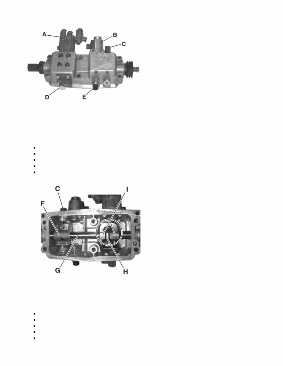
The control housing is made of aluminium.
The control shaft and control housing have been adjusted for the optional construction of left-hand and
right-hand driven vehicles.
Inhibitor cylinder (A)
Solenoid for the first gear inhibitor (B)
Neutral/reverse inhibitor with adjusting spacer (C)
Inhibitor valve (D)
Reverse light contact with pin (E)
The function of the control housing is to transfer the gear shift movement to the selector bars in the
gearbox and consists primarily of:
The control shaft (G) on which the gear shift is attached.
The gear selector (H) on the gear shift affects the selector bars.
The gear position detent (I) prevents two selector bars from being affected at the same time.
The control shaft is also equipped with a neutral/reverse inhibitor (C) that keeps the gears in place.
In addition, the lock functions as a gear lever resistor when put into reverse/crawl.
Page 2 of 14 sb22633_node3
6/25/2007 http://127.0.0.1:9905/impact3/application/staticdb/lang/enGB/sb22633_node3.xhtm
The neutral/reverse inhibitor locks against the cam (F) on the control shaft. The cam also has a
catch that is locked by the first gear inhibitor's solenoid.
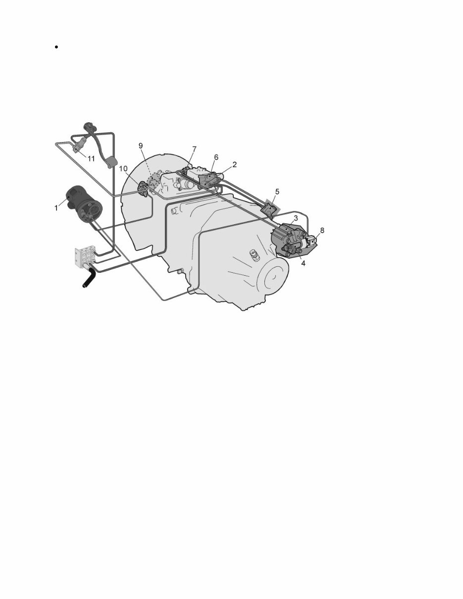
Pneumatic system
Positioning of pneumatic components
1. Gear lever
2. Air filter
3. Range cylinder
4. Relay valve range
5. Inhibitor valve for range housing
6. Interlock cylinder
7. Inhibitor valve for control housing
8. Range inhibitor
9. Split cylinder
10. Split relay valve
11. Split inhibitor valve
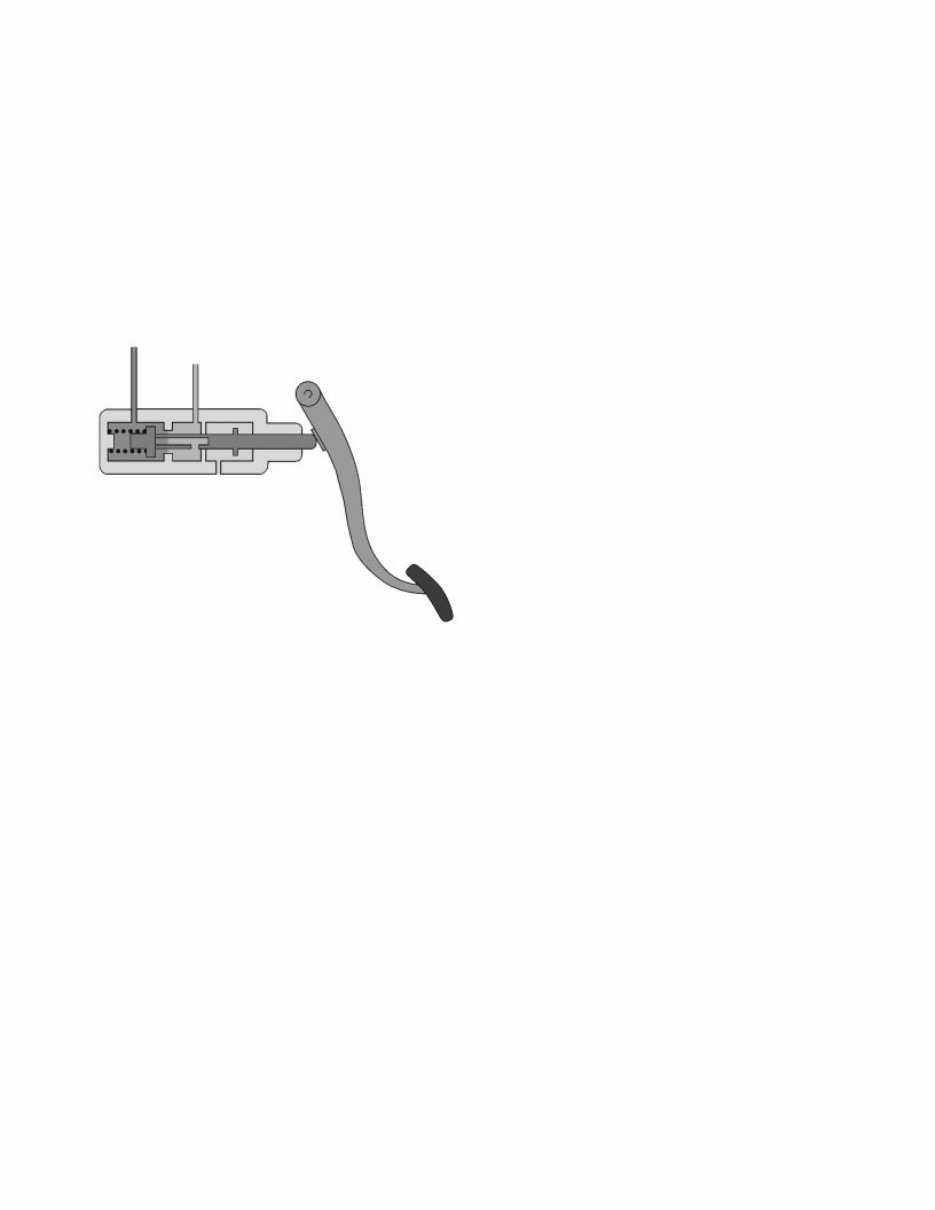
Gear lever
Page 3 of 14 sb22633_node3
6/25/2007 http://127.0.0.1:9905/impact3/application/staticdb/lang/enGB/sb22633_node3.xhtm
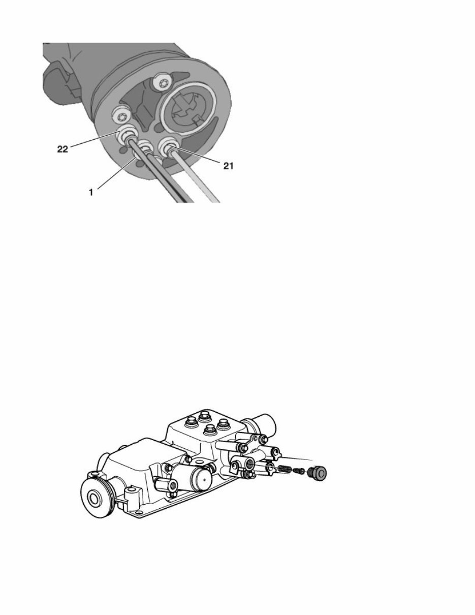
The range gear control is positioned on the gear lever. This consists of a valve that stops or lets through
control air to the relay valve on the range cylinder.
The split gear control that stops or lets through control air to the split cylinder relay valve is also
positioned on the gear lever.
The gear lever is fed with pressurised air through the connection (1). When the range control is set on
low range, control air is let out through the connection (21). When it is set on high range, a connection is
made via the gear lever.
When the split control is set on high split, control air is let out through the connection (22). When it is
set on low split, a ventilation is performed through the gear lever.
Air filter
Page 4 of 14 sb22633_node3
6/25/2007 http://127.0.0.1:9905/impact3/application/staticdb/lang/enGB/sb22633_node3.xhtm
The pneumatic system's gearbox feeder is fitted with an air filter. This is positioned on the cover of the
inhibitor cylinder on the control housing.
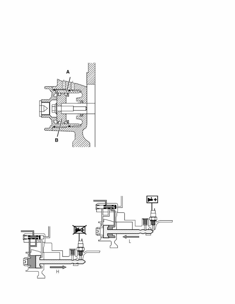
Range cylinder
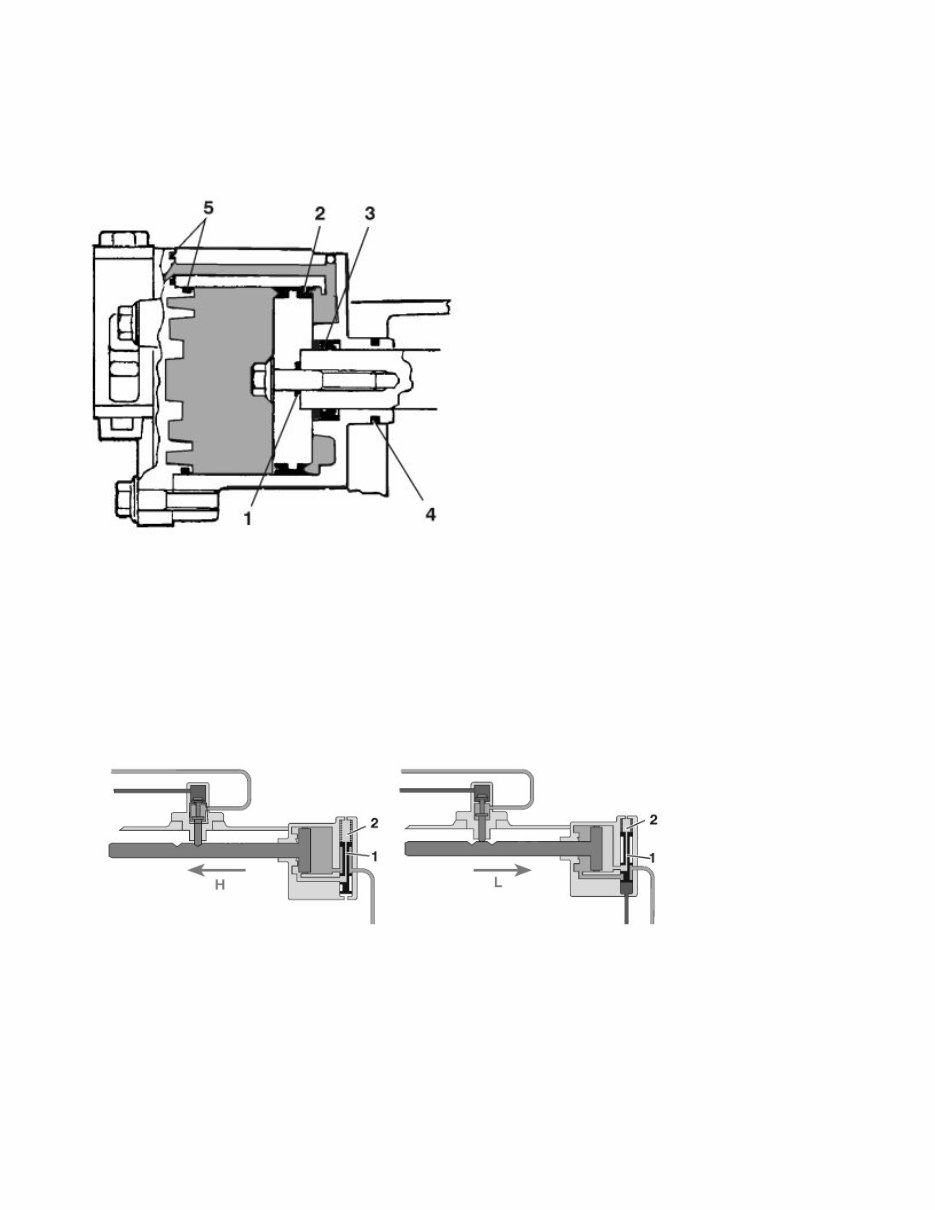
The range cylinder is a double-acting pneumatic cylinder attached to the back of the range housing. The
piston is screwed onto the piston rod and the coupling is sealed with an O-ring (1). Other seals comprise
of a piston seal (2), a piston rod seal (3), the O-ring seal on the range housing (4) and the O-rings on the
cover (5).
Relay valve range
The function of the relay valve is to direct the air to one side of the piston depending on the choice of
gear. The relay valve is integrated in the cylinder cover.
The relay valve is fitted with a spring-loaded control slide (1) that is set on high range (H) by a spring
force (2). When the control on the gear lever is set on low range (L), control air is let through to the
relay valve, overcoming the spring force and making the control slide shift a to low range level.
Page 5 of 14 sb22633_node3
6/25/2007 http://127.0.0.1:9905/impact3/application/staticdb/lang/enGB/sb22633_node3.xhtm
The cylinder is ventilated through the relay valve.
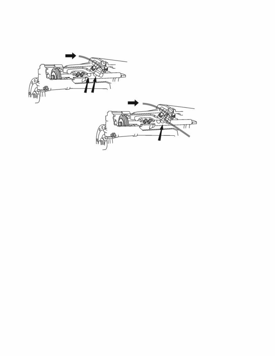
Inhibitor valve range housing
When changing the range gear, the base gearbox is locked by the inhibitor cylinder in the control
housing. The inhibitor valve controls the feed air to the inhibitor cylinder. The inhibitor valve is
controlled by the range cylinder piston rod in the following way:
The piston rod has two indents. The piston of the inhibitor valve is located in one of these indents when
the range gear is set to a high or low range level.
The valve then blocks the air supply to the inhibitor cylinder on the control housing.
When changing the range gear, the inhibitor valve's piston is pushed out of the indent, opening the air
supply to the inhibitor cylinder.
Inhibitor cylinder
Page 6 of 14 sb22633_node3
6/25/2007 http://127.0.0.1:9905/impact3/application/staticdb/lang/enGB/sb22633_node3.xhtm
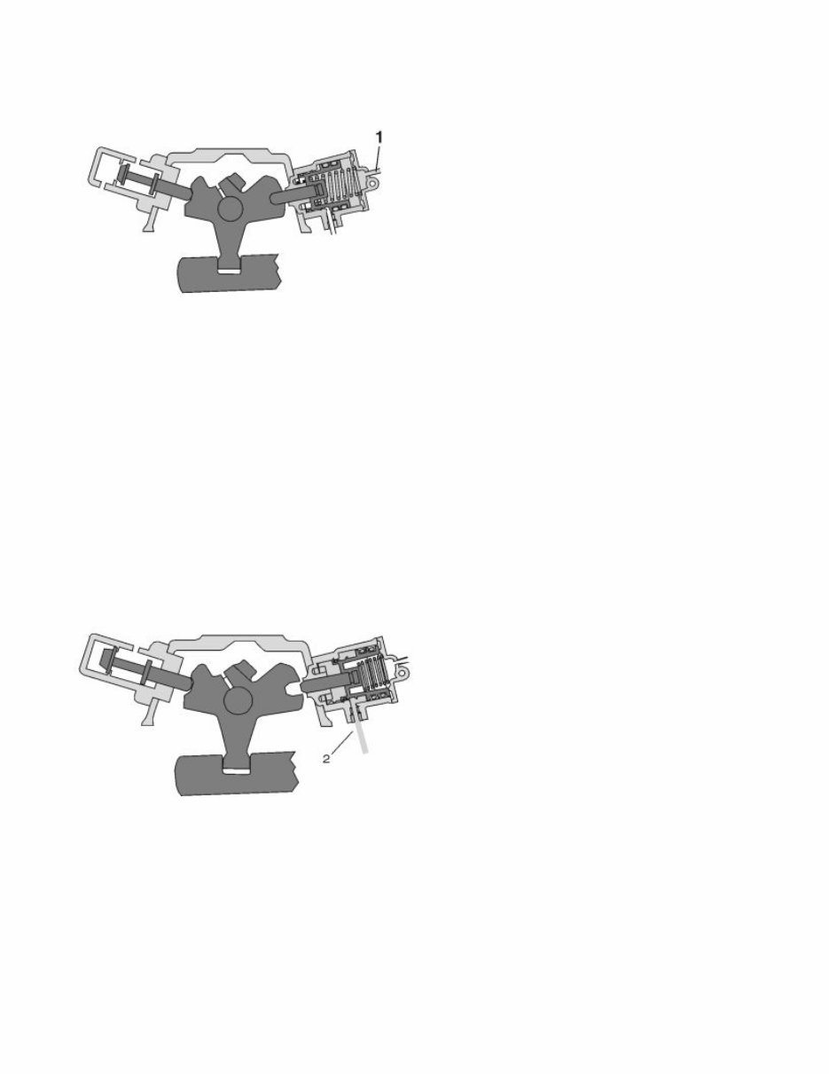
The inhibitor cylinder on the control housing stops the base gearbox from being manually changed when
the range gear is changed.
The inhibitor cylinder consists of a double-action spring-loaded cylinder and a piston with a stop pin.
When changing the range gear, air from the inhibitor valve on the range gear is emitted into the
connection (1) at the same time as the force of the spring pushes the stop pin into the recess on the gear
selector. The base gearbox is then locked into neutral position.
The inhibitor cylinder is also used to lock the gear lever in a neutral position when releasing the clutch
pedal. This results in the driver always having to depress the clutch pedal before engaging the start gear.
When the clutch pedal is depressed, air from the split inhibitor valve is emitted into the connection (2).
The air overcomes the spring force, putting the gear selector into neutral.
Page 7 of 14 sb22633_node3
6/25/2007 http://127.0.0.1:9905/impact3/application/staticdb/lang/enGB/sb22633_node3.xhtm
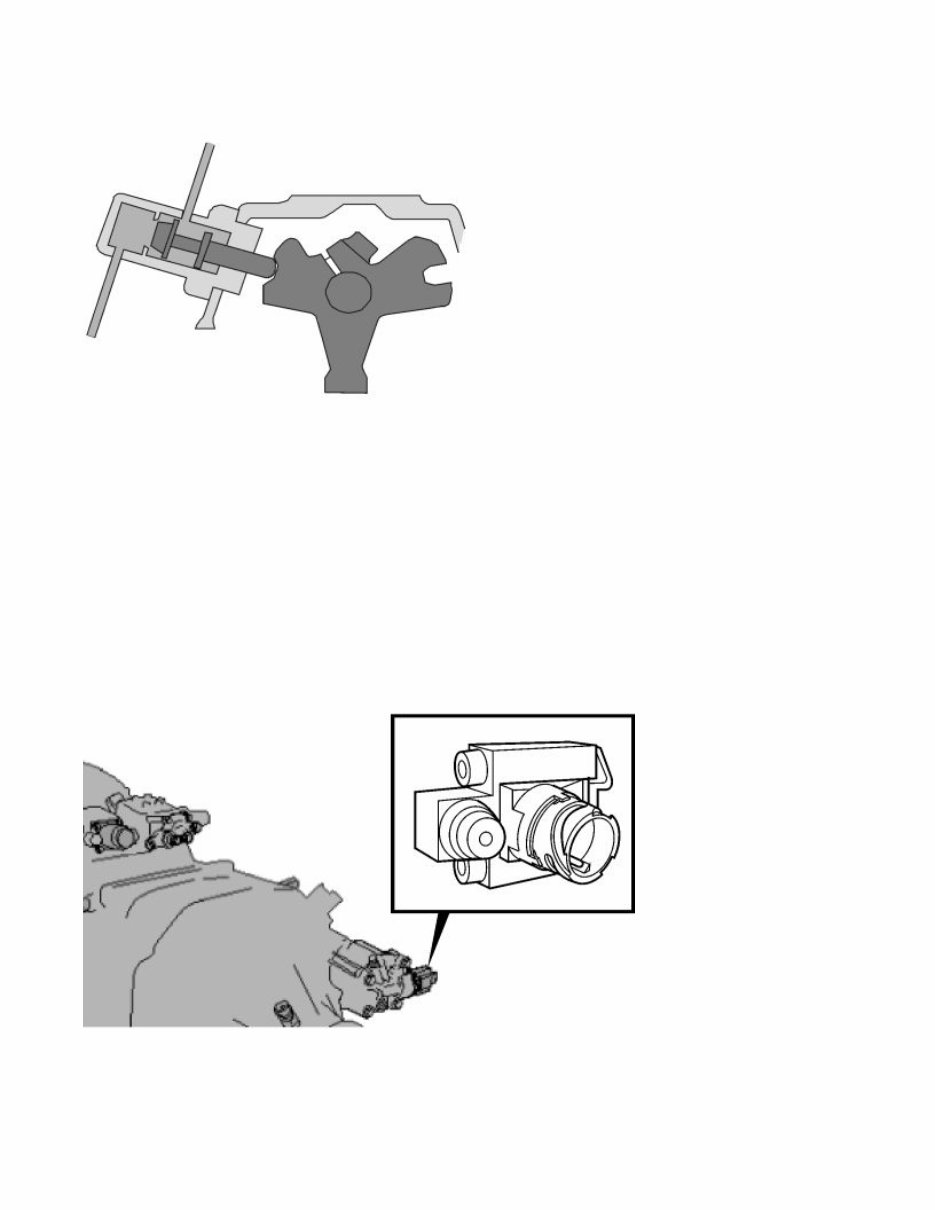
Inhibitor valve control housing
When any of the gears in the base gearbox is engaged, a change of range gear is not possible. This is
carried out by an inhibitor valve that functions in the opposite way to the inhibitor valve on the range
housing.
When the gear lever is put in neutral, the inhibitor valve opens for the feed air to pass through to the
range cylinder.
When a gear is engaged, the gear selector pushes in the piston on the inhibitor valve, shutting off the air
supply to the range cylinder.
Range inhibitor
The range inhibitor prevents a change to low range when the rotation speed on the output shaft of the
gearbox exceeds 700 rpm (approx. 30 km/h).
Page 8 of 14 sb22633_node3
6/25/2007 http://127.0.0.1:9905/impact3/application/staticdb/lang/enGB/sb22633_node3.xhtm
The vehicle control unit (VECU) receives a signal from the vehicle speed sensor and activates the
solenoid valve that in turn shuts off the control air to the range cylinder relay valve, preventing a low
range from being engaged.
The solenoid valve is positioned on the cover of the range cylinder.
Split cylinder
The split cylinder is a double-action pneumatic cylinder inside the clutch housing.
The cover and cylinder are made in one piece (A). The piston (B) is screwed onto the piston rod. The
inhibitor that holds the split gear in place is situated to the left of the base gearbox, next to the split
switch.
Relay valve split
Page 9 of 14 sb22633_node3
6/25/2007 http://127.0.0.1:9905/impact3/application/staticdb/lang/enGB/sb22633_node3.xhtm
The split cylinder relay valve acts in the same way as the range cylinder relay valve.
The relay valve slide is kept in a low split position (L) by the spring force.
When the gear lever control is put in a high split position (H), air is emitted from the relay valve,
overcoming the spring force and putting the control slide in a high split position.
(Only applies to direct drive gearbox, DD)
Inhibitor valve split
The split gear cannot be changed unless the clutch pedal is depressed. The feed air supply to the split
cylinder is therefore controlled by an inhibitor valve.
When depressing the clutch pedal, the inhibitor piston is pushed in, opening the valve and letting
through feed air to the split cylinder.
Electrical system
Page 10 of 14 sb22633_node3
6/25/2007 http://127.0.0.1:9905/impact3/application/staticdb/lang/enGB/sb22633_node3.xhtm
You're Reading a Preview
What's Included?
Fast Download Speeds
Online & Offline Access
Access PDF Contents & Bookmarks
Full Search Facility
Print one or all pages of your manual
$41.99
Viewed 14 Times Today


Secure transaction
What's Included?
Fast Download Speeds
Online & Offline Access
Access PDF Contents & Bookmarks
Full Search Facility
Print one or all pages of your manual
$41.99
The Volvo FH truck VTO2514B Gearbox construction manual provides detailed information on the design and function of the gearbox. It covers the following key areas:
- Gear selector housing
- Pneumatic system
- Electrical system
- Lubricating system
- Gear selector housing
This manual is valuable for both professional mechanics and DIY enthusiasts seeking comprehensive insights into the gearbox construction of the Volvo FH truck.


