

2012-2013 Mitsubishi Fuso Canter FE FG Service & Repair Manual
What's Included?
Fast Download Speeds
Online & Offline Access
Access PDF Contents & Bookmarks
Full Search Facility
Print one or all pages of your manual

SERVICE MANUAL
2012 Model
FOREWORD
This Service Manual contains maintenance and repair
methods for the Mitsubishi Fuso Truck FE. FG Series.
Read this manual carefully as an aid in providing cor-
rect, efficient maintenance. Please note that the infor-
mation and specifications contained within this manual
may change without notice. This is due to product
modifications and continued vehicle improvements
that are made throughout the model years. Should you
encounter any discrepancy in the information provid-
ed, please do not hesitate to contact your nearest Mi-
tsubishi Fuso Dealer or Mitsubishi Fuso Truck of
America, Inc.
MARCH 2011
GROUP INDEX
GENERAL .............................................. 00
MAINTENANCE SCHEDULE ................. 01
ENGINE................................................... 11
LUBRICATION ........................................ 12
FUEL AND ENGINE CONTROL ............. 13
COMMON RAIL SYSTEM....................... 13E
COOLING................................................ 14
INTAKE AND EXHAUST ........................ 15
EMISSION CONTROL ............................ 17
BlueTec® SYSTEM ................................ 17E
CLUTCH.................................................. 21
TRANSMISSION <DUONIC
TM
> ............. 22
DUONIC
TM
.............................................. 22E
TRANSFER ............................................. 24
PROPELLER SHAFT ............................. 25
FRONT AXLE
<FE> ..................................................... 26A
<FG> ..................................................... 26B
REAR AXLE............................................ 27
WHEEL AND TIRE ................................. 31
FRONT SUSPENSION ........................... 33
REAR SUSPENSION.............................. 34
BRAKE.................................................... 35
ANTI-LOCK BRAKE SYSTEM (ABS) .... 35E
PARKING BRAKE .................................. 36
STEERING .............................................. 37
BUMPER AND FRAME .......................... 41
CAB......................................................... 42
DOOR...................................................... 43
EXTERIOR .............................................. 51
INTERIOR ............................................... 52
ELECTRICAL .......................................... 54
HEATER, AIR-CONDITIONER
AND VENTILATION ................................ 55
FULL AUTOMATIC
AIR-CONDITIONER ................................ 55E

General
Group 00
Pub.No.00ELT0001-00

00-1
INDEX
EQUIPMENT TYPE CODES LIST ....................................................... 00-2
POWER TRAIN TABLE ....................................................................... 00-3
HOW TO READ THIS MANUAL.......................................................... 00-4
CHASSIS NUMBER, ENGINE NUMBER,
POWER TRAIN LABEL..................................................................... 00-12
VEHICLE IDENTIFICATION NUMBER ............................................. 00-13
PRECAUTIONS FOR MAINTENANCE OPERATION
1. Handling Precautions for Electric Circuits .................................. 00-19
2. Service Precautions for Alternators ............................................ 00-22
3. Intermittent Faults ....................................................................... 00-24
4. Precautions for Arc Welding ....................................................... 00-25
5. Cautions When Handling DEF ..................................................... 00-26
6. Precautions When Repainting ..................................................... 00-26
7. Precautions When Handling a Vehicle with DUONIC
TM
System ... 00-26
8. Precautions on Cleaning When Servicing the Engine and
Transmission .............................................................................. 00-27
JACKING UP THE VEHICLE ............................................................ 00-30
DIAGNOSIS CODES
1. Diagnosis Codes ......................................................................... 00-34
2. Reading and Erasing the Diagnosis Code ................................... 00-40
TABLE OF STANDARD TIGHTENING TORQUES........................... 00-44
00-2
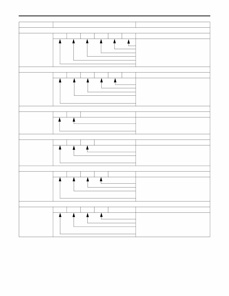
Component Name plate marking Code description
Engine
4P10T5 4 P 1 0 T 5
Power version number
Turbocharged
Order of development within same series
Order of development among different series
Diesel engine
No. of cylinders (4)
Transmission
M038S6W M 038 S 6 W
Variation (W: With directly-mounted transfer)
Forward speeds
Type of mesh (S: Synchromesh)
Load carrying capacity of truck class (tonnage)
on which the clutch is primarily used
Initial letter of the transmission
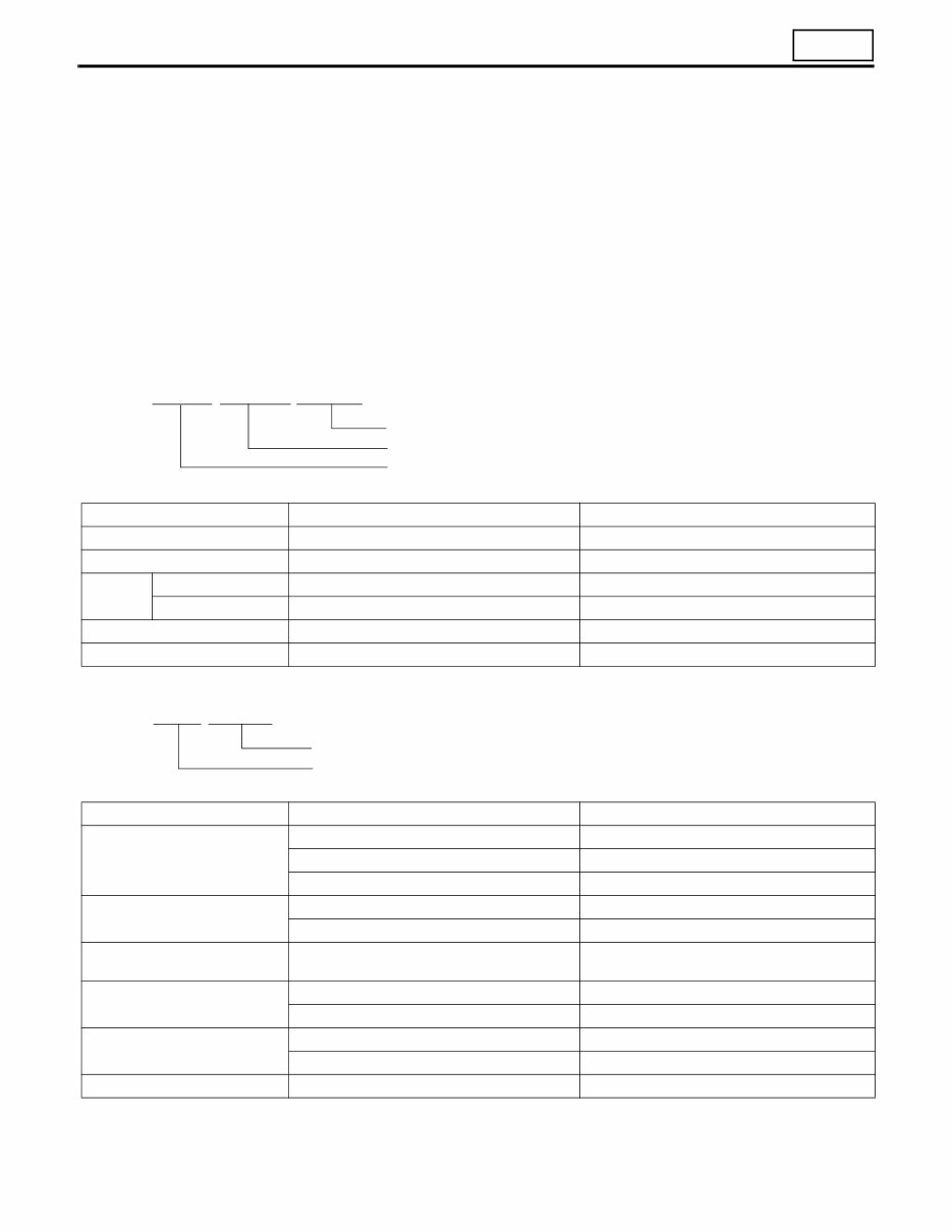
Propeller shaft
P3 P 3
Load carrying capacity of truck class (tonnage)
on which the clutch is primarily used
Initial letter of the propeller shaft
Front axle
F200T F 200 T
Vehicle type (T: Truck)
Load carrying capacity of truck class (tonnage)
on which the clutch is primarily used
Initial letter of the front axle
Rear axle
R033T R 03 3 T
Vehicle type (T: Truck)
Order of development within same series
Load carrying capacity of truck class (tonnage)
on which the clutch is primarily used
Initial letter of the rear axle
Reduction and differential
D033H D 03 3 H
Tooth profile (H: Hypoid gear)
Order of development within same series
Load carrying capacity of truck class (tonnage)
on which the clutch is primarily used
Initial letter of the reduction & differential
EQUIPMENT TYPE CODES LIST

00
00-3
Vehicle model Engine Clutch Transmission Propeller shaft Rear axle
Reduction &
differential
FEC52CL3SUHD 4P10-T5 – M038S6 P3 R033T D033H
FEC52EL3SUHD 4P10-T5 – M038S6 P3 R033T D033H
FEC52GL3SUHD 4P10-T5 – M038S6 P3 R033T D033H
FEC72CL3SUHD 4P10-T5 – M038S6 P3 R035T D035H
FEC72EL3SUHD 4P10-T5 – M038S6 P3 R035T D035H
FEC72GL3SUHD 4P10-T5 – M038S6 P3 R035T D035H
FEC72HL3SUHD 4P10-T5 – M038S6 P3 R035T D035H
FEC72KL3SUHD 4P10-T5 – M038S6 P3 R035T D035H
FEC72HL3WUHD 4P10-T5 – M038S6 P3 R035T D035H
FEC72KL3WUHD 4P10-T5 – M038S6 P3 R035T D035H
FEC92CL3SUHD 4P10-T5 – M038S6 P3 R035T D035H
FEC92EL3SUHD 4P10-T5 – M038S6 P3 R035T D035H
FEC92GL3SUHD 4P10-T5 – M038S6 P3 R035T D035H
FEC92HL3SUHD 4P10-T5 – M038S6 P3 R035T D035H
FEC92KL3SUHD 4P10-T5 – M038S6 P3 R035T D035H
FGB72EL3SUHD 4P10-T5 – M038S6W
Front: P2
Rear: P3
R035T
Front: D1H
Rear: D035H
POWER TRAIN TABLE

00-4
This manual consists of the following parts:
• Specifications
• Structure and Operation
• Troubleshooting
• Circuits
• Electrical Equipment Installation Positions
• Inspection of Electrical Equipment
• On-vehicle Inspection and Adjustment
• Connector configuration chart
On-vehicle Inspection and Adjustment
• Procedures for inspection and adjustment of individual parts and assemblies as mounted on the vehicle are de-
scribed including specific items to check and adjust. Specified or otherwise, inspection should be performed for
looseness, play, backlash, crack, damage, etc.
Service procedures
• Procedures for servicing components and parts off the vehicle are described centering on key points in their re-
moval, installation, disassembly, reassembly, inspection, etc.
Inspection
• Check items subject to “acceptable/unacceptable” judgement on the basis of service standards are all given.
• Some routine visual checks and cleaning of some reused parts are not described but must always be included in
actual service work.
Caution
• This service manual contains important cautionary instructions and supplementary information under the following
four headings which identify the nature of the instructions and information:
Terms and Units
• Front and rear
The forward running direction of the vehicle is referred to as the front and the reverse running direction is referred
to as the rear.
• Left and right
Left hand side and right hand side, when facing the forward running direction of the vehicle, are respectively left
and right.
Standard value
• Standard value dimensions in designs indicating: the design dimensions of individual parts, the standard clear-
ance between two parts when assembled, and the standard value for an assembly part, as the case may be.
DANGER
Precautions that should be taken in handling potentially dangerous substances
such as battery fluid and coolant additives.
WARNING
Precautionary instructions, which, if not observed, could result in serious injury or
death.
CAUTION
Precautionary instructions, which, if not observed, could result in damage to or de-
struction of equipment or parts.
NOTE
Suggestions or supplementary information for more efficient use of equipment or
better understanding.
HOW TO READ THIS MANUAL
00
00-5
Limit
• When the value of a part exceeds this, it is no longer serviceable in respect of performance and strength and must
be replaced or repaired.
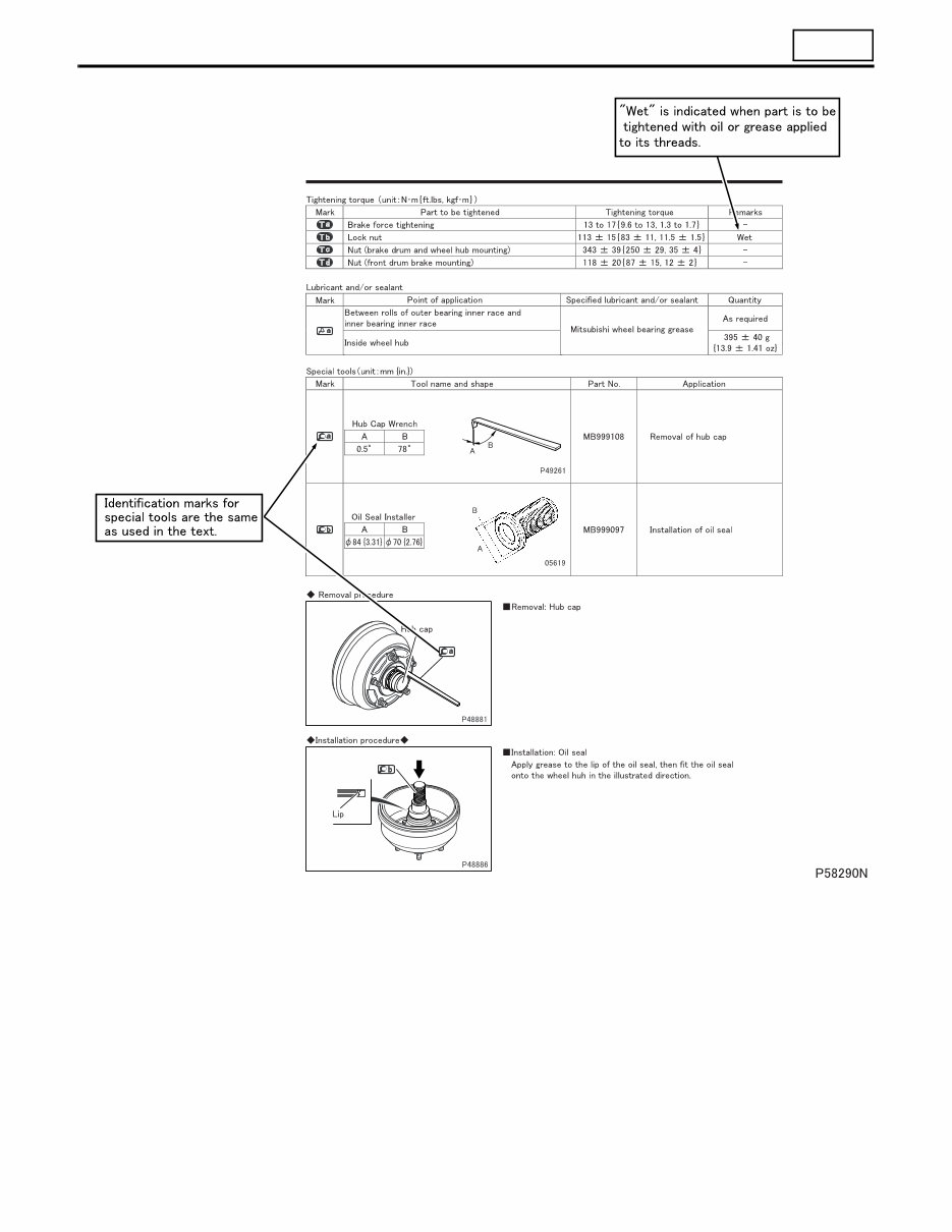
Tightening torque
• Values are directly specified for out-of-standard tightening torques for bolts and nuts.
• Where there is no specified figure for tightening torque, follow the table covering standard tightening torques.
(Values for standard tightening torques are based on thread size and material.)
• When the item is to be tightened in a wet state, “wet” is indicated. Where there is no indication, read it as dry.
Units
• Tightening torques and other parameters are given in SI* units with imperial unit and metric units added in brack-
ets { }.
*SI: Le Système International d’Unités
Unit SI unit {imperial unit, metric unit} Conversion factor
Force N {lbs, kgf} 9.80665 N {2.2046 lbs, 1 kgf}
Moment of force N·m {ft.lbs, kgf·m} 9.80665 N·m {7.2329 ft.lbs, 1 kgf·m}
Pressure
Positive pressure kPa {psi, kgf/cm
2
} 98.0665 kPa {14.22 psi, 1 kgf/cm
2
}
Vacuum pressure kPa {in.Hg, mmHg} 0.133322 kPa {0.03937 in.Hg, 1 mmHg}
Volume J {BTU, kcal} 4186.05 J {3.96825BTU, 1 kcal}
Heat quantity W {BTU/h, kcal/h} 1.16279W {3.96825BTU/h, 1 kcal/h}
Unit SI unit {imperial unit} Conversion factor
Length
mm {in.} 1 mm {0.03937 in.}
m {ft.} 1 m {3.2808 ft.}
km {mile} 1 km {0.6214 mile}
Mass
kg {lb} 1 kg {2.2046 lb}
g {oz} 1 g {0.035274 oz}
Temperature
(in degree Celsius)
°C {°F} 1°C {(1°C × 1.8 + 32)°F}
Velocity
km/h {mph} 1 km/h {0.6214 mph}
m/s {ft/s} 1 m/s {3.281 ft/s}
Volume
L {qts}, L {gal} 1 L {1.05336 qts}, 1 L {0.2642 gal}
cm
3
{cu.in.} 1 cm
3
{0.061023 cu.in.}
Area m
2
{in
2
}, m
2
{ft
2
} 1 m
2
{1.550 × 10
3
in
2
}, 1 m
2
{1.076 × 10 ft
2
}
Example: 390 N·m {290 ft.lbs, 40 kgf·m}
Metric unit
SI unit
Imperial unit
Example: 30 mm {1.18 in.}
SI unit
Imperial unit
00-6
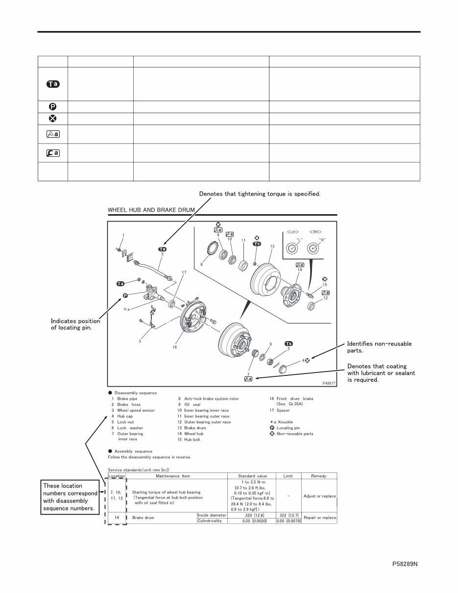
Illustrated Parts Breakdown and Service Procedures
Symbol Denotation Application Remarks
Tightening torque
Parts not tightened to standard torques
(standard torques specified where neces-
sary for servicing)
Specified values shown in table
See Table of Standard Tightening Torques for
parts for which no tightening torques are speci-
fied.
Locating pin Parts to be positioned for installation
Non-reusable parts Parts not to be reused
Lubricant and/or
sealant
Parts to be coated with lubricant or sealant
for assembly or installation
Necessary lubricant and/or sealant, quantity re-
quired, etc. are specified in table.
Special tool
Parts for which special tools are required for
service operation
Tool name/shape and part number are shown in
table.
*a Associated part
Parts associated with those removed/disas-
sembled for servicing
HOW TO READ THIS MANUAL
00
00-7
You're Reading a Preview
What's Included?
Fast Download Speeds
Online & Offline Access
Access PDF Contents & Bookmarks
Full Search Facility
Print one or all pages of your manual
$52.99
Viewed 76 Times Today


Secure transaction
What's Included?
Fast Download Speeds
Online & Offline Access
Access PDF Contents & Bookmarks
Full Search Facility
Print one or all pages of your manual
$52.99
The Mitsubishi-Fuso Canter 2012-2013 factory workshop/repair manual is a valuable resource for both professional mechanics and DIY enthusiasts. It is a searchable manual that covers a wide range of technical information essential for car repair.
- GENERAL
- MAINTENANCE SCHEDULE - 01
- ENGINE - 4P10T5
- LUBRICATION
- FUEL AND ENGINE CONTROL - 13
- COMMON RAIL SYSTEM - 13E
- COOLING
- INTAKE AND EXHAUST - 15
- EMISSION CONTROL - 17
- BlueTec® SYSTEM - 17E
- CLUTCH
- TRANSMISSION - M038S6W
- DUONICTM
- TRANSFER
- PROPELLER SHAFT - 25
- FRONT AXLE 2WD and 4WD
- REAR AXLE
- WHEEL AND TIRE - 31
- FRONT SUSPENSION - 33
- REAR SUSPENSION - 34
- BRAKE
- ANTI-LOCK BRAKE SYSTEM (ABS) - 35E
- PARKING BRAKE - 36
- STEERING
- BUMPER AND FRAME - 41
- CAB
- DOOR
- EXTERIOR
- INTERIOR
- ELECTRICAL
- HEATER, AIR-CONDITIONER AND VENTILATION
- FULL AUTOMATIC AIR-CONDITIONER
These manuals provide comprehensive information on the repair and maintenance of the Mitsubishi-Fuso Canter, making them an indispensable tool for anyone working on these vehicles.


