

HINO Truck 700 Series Wiring Electrical Diagram Manual
What's Included?
Fast Download Speeds
Online & Offline Access
Access PDF Contents & Bookmarks
Full Search Facility
Print one or all pages of your manual
FOREWORD
This workshop manual has been prepared to provide information on electrical circuits for the following Hino Vehicles.
Applicable for FR1E, FS1E, FY1E, SH1E, SR1E and SS1E series, equipped with E13C engine
As for maintenance items, refer to the Owner’s Manual.
All information and specifications in this manual are based upon the latest product information available at the time of print-
ing.
Hino Motors reserves the right to make changes at any time without prior notice.
Please note that the publications below have also been prepared as relevant service manuals for the components and sys-
tems in this vehicles.
Manual Name Pub. No.
Chassis Workshop Manual
S1-YFSE17C 1/2
S1-YFSE17C 2/2
E13C Engine Workshop Manual S5-YE13E02C


WORKSHOP
MANUAL
ELECTRIC WIRE
INDEX: CHASSIS GROUP
All rights reserved. This manual may not be
reproduced or copied in whole in part, with-
out the written consent of Hino Motors, Ltd.


ELECTRIC WIRE EL02–1
EL02ELECTRIC WIRE
EL02-001
DIAGRAM.................................................. EL02-2
HOW TO USE THIS CHAPTER........................ EL02-2
CONTENTS OF DIAGRAMS ............................ EL02-7
WIRING DIAGRAM......................................... EL02-11
DIAGRAM ....................................................... EL02-12
WIRE TO WIRE CONNECTOR .................... EL02-142
JUNCITON CONNECTOR............................ EL02-161
CONNECTOR LOCATION ............................ EL02-167
RELAY LOCATION ....................................... EL02-240
FUSE AND RELAY BLOCK .......................... EL02-242
JUNCTION BLOCK ...................................... EL02-254
WIRE TO WIRE BOX .................................... EL02-258
ELECTRICAL EQUIPMENT BOX ................. EL02-260
CONNECTOR INDEX ................................... EL02-261
ELECTRIC WIRE EL02–2
DIAGRAM
HOW TO USE THIS CHAPTER
EN12Z1602J100001
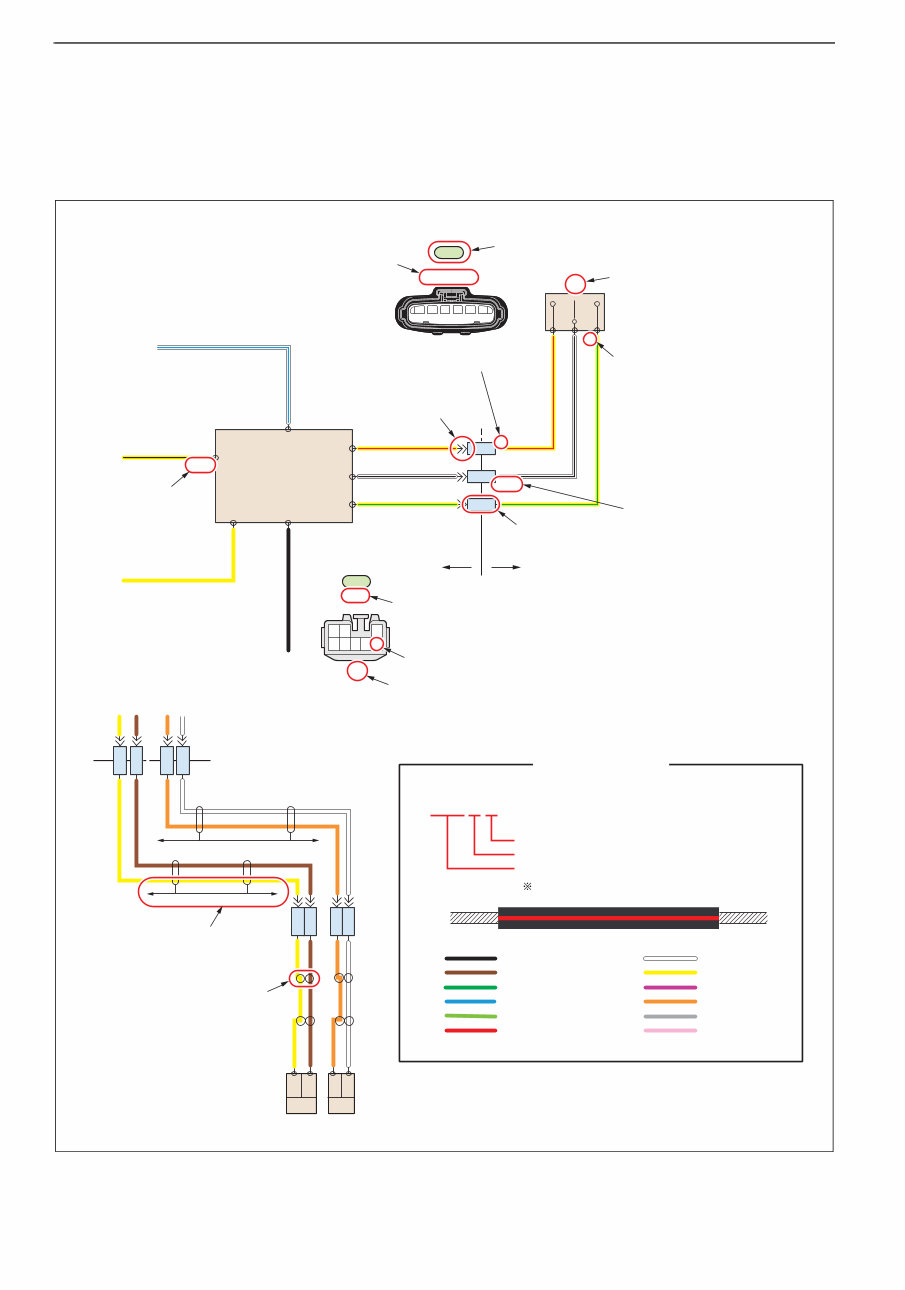
1. WIRING DIAGRAM
(%AD)
13
(%AE)14
(%AF)
15
(%AJ)
20
(#AT)
27
(#B2)
8
(#AU)
22
(#B3)
11
0.50 W-L
5 0.50 Y-R
0.50 Y-R
0.50 W-B
0.50 B
0.50 Y-G
8
(SLX)
(+)
3 0.50 W-B
(B+2)
(LDS+)
3
(M)
1
(-)
2
2 0.50 Y-G
(SULK)
1
(E- )
7
(LDS- )
4
(B+ )
1
2
f-a 4
f-a 4
f-a 4
14
13
15
0.50 Y-B
0.50 Y
0.50 Y
0.50 BR
0.50 O
0.50 W
%28
(ABS)
%2A
(ABS)
%27
(ABS)
%29
(ABS)
0.01 SH-LD
0.01 SH-LD
0.50 Y
0.50 O
0.50 W
0.50 BR
1 (SRL+)
2 (SRLE)
1
(SRR+)
2
(SRRE)
15 16
c-a 3
c-a 3
d-c 1
d-c 1
d-c 1
d-c 1
c-a 3
c-a 3
($22)
($21)
($23)
2 3 4 5 6 1
g7
CA-2
82560-3300
1
a75
IP-7
82580-6870
2
3 2 1
8 5 4 7 6
Code for the connector
of the male side
Terminal number
Connector code
Part number
Terminal number
Terminal code Terminal code
Code of the wire to wire connector
"a" wiring harness side "f" wiring harness side
Terminal number
Serial number in the circuit diagram
Serial number in the circuit diagram
Code of the area specifying this connecor
in the section "CONNECTOR LOCATION"
Twisted-pair cable
Shielded cable
3.00 R-Y
Second letter: Stripe color
First letter: Ground wire color
Arabic numerals: Cross sectional area of wire
B: Black
BR: Brown
G: Green
L: Blue
LG: Light Green
R: Red
W: White
Y: Yellow
V: Violet
O: Orange
GR: Gray
P: Pink
Example: 3.00 indicates 3 mm {0.0047 in. }
2 2
Wiring color code
Second letter: Stripe color
Terminal code
(EXAMPLE)
SHTS12Z160200001
ELECTRIC WIRE EL02–3
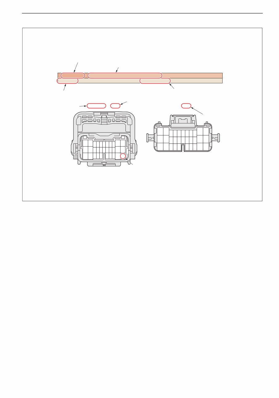
2. WIRE TO WIRE CONNECTOR
24
17
25
18 19
9
10
7 8
20
11
3
26 27 28 29 30 31 32
22
14
6
2
13
5
1
21 12
4
15 16
23
6
18
30
2
3 4 5 9 8
10 11
12 13
14
23 24 25 26
15 16 17
21
20
22
27 28 29 32 31
1
7
19
GE, HE, LA IP-1, EG-5, EG-10
a-b 3 / b-a 3 Cab main wiring harness to Front wiring harness 3
82560-2170, Gray, Male 82560-2180, Gray, Female
Terminal number
Connector color
Code of the circuit diagram specifying this connecor
in the section "WIRING DIAGRAM"
Code of the area specifying this connecor
in the section "CONNECTOR LOCATION"
LH side: Male connector or the wiring harness "a" (Cab main wiring harness)
RH side: Female connector or the wiring harness "b" (Front wiring harness)
Connector code
[This case indicates that wire harness "a" (Cab main harness) and
wire harness "b" (Front wiring harness) should be connected, which is serial No.3 wire to wire connector.]
Part number
Classification
by male/female
Name of the wiring harness to be connected.
SHTS12Z160200002
ELECTRIC WIRE EL02–4
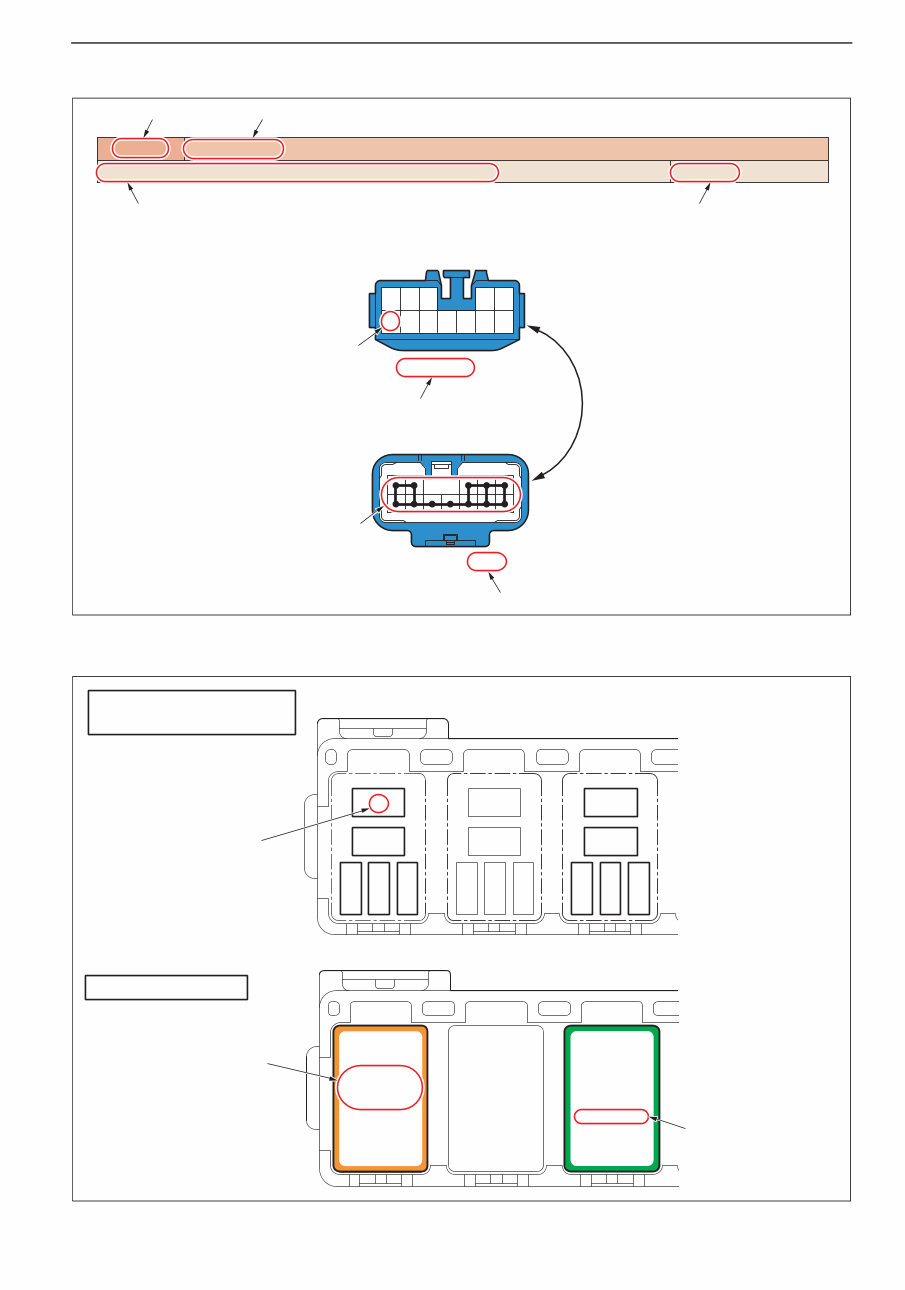
3. JUNCTION CONNECTOR
(EXAMPLE)
ELECTRIC WIRE EL02–205
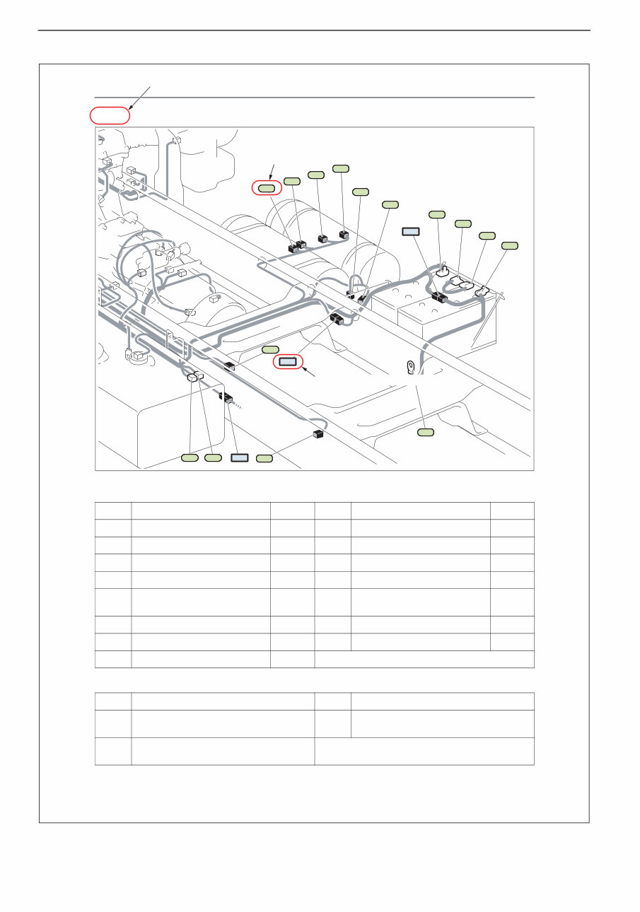
EG-26 [ENGINE (3 of 3)] (Model: FM8J for Chile)
ELECTRICAL EQUIPMENT CONNECTOR AND JUNCTION CONNECTOR
WIRE TO WIRE CONNECTOR
No. Name Circuit No. Name Circuit
b10 Low pressure switch 1 BB ba1 Battery (+) terminal (Battery 2) AA
b11 Low pressure switch 2 BB bb1 Battery (+) terminal (Battery 1) AA
b12 Low pressure switch 3 BB bb2 Battery (-) terminal (Battery 2) AA
b13 Air gauge sensor (Front) BB bc1 Battery (-) terminal (Battery 1) AA
b14 Air gauge sensor (Rear) BB bc2 Battery ground
AA, BA,
MA
b24 Exhaust brake magnetic valve GE sk2 P.T.O. magnetic valve KB
b45 Dump up switch KB sl1 P.T.O. accelerator sensor GK
b46 Service power (Tail) AB
No. Name No. Name
b-c 2
Front wiring harness to
Intermediate wiring harness 2
ba-bc 1
Battery cable-1 to
Battery cable-3_1
b-ba 1
Front wiring harness to
Battery cable-1_1
ba1
b11
b13
b14
b10
b12
b24
bb2
bb1
bc2
sl1
b45 b46 sk2 b-c 2
b-ba 1
bc1
ba-bc 1
SHTS12Z160200166
Connector code
Code of the wire to wire connector
Code of the area
SHTS12Z160200003
ELECTRIC WIRE EL02–5
4. JUNCTION CONNECTOR
5. FUSE AND RELAY BLOCK
82580-8740, Blue
82550-1040, Blue
1 2 3 4 5
6 7 8 9 10 11 12
Ja13
AC, BA, CB, CE, DA, EA, EB, ED, EG, EO, HA, IA, KA, KB, KC, LA, MA IP-3, IP-7
J/C Earth G3
Part number
Terminal number
Connector color
Code of the circuit diagram specifying this connecor
in the section "WIRING DIAGRAM"
Code of the area specifying this connecor
in the section "CONNECTOR LOCATION"
Connector name Connector code
Internal wire connection
SHTS12Z160200004
MZ12
Power shift
relay
85920-2770
2
1
3 4 5
MZ12
Over-run
relay
85920-2680
1
2
3 4 5
FUSE AND RELAY BLOCK
TERMINAL ALIGNMENT
RELAY ALIGNMENT
Part number
Terminal number
Relay name
SHTS12Z160200005
ELECTRIC WIRE EL02–6
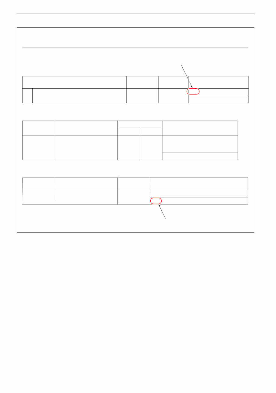
6. CONNECTOR INDEX
(EXAMPLE)
ELECTRIC WIRE EL02–192
CONNECTOR INDEX
ELECTRICAL EQUIPMENT CONNECTOR
WIRE TO WIRE CONNECTOR
JUNCTION CONNECTOR
NAME
CONNECTOR
No.
PART No. CIRCUIT OR AREA
A ABS diagnosis switch a100 82560-4100
HB
IP-4, 8
CONNECTOR
No.
NAME
PART No.
CIRCUIT OR AREA
MALE FEMALE
a-b 1
Cab main wiring harness to
Front wiring harness 1
82560-
2110
82560-
2120
AA, AB, AD, AG, BA, BG, BH, CA, CB,
CE, CH, CI, GA, GB, GC, GE, HA, HB,
HC, HE, IA, LA, LE, MA
IP-1, 5, EG-1, 2, 3, 5, 6, 10, 11, 16, 17
CONNECTOR
No.
NAME PART No. CIRCUIT OR AREA
a606
FA, IE
IP-2
J/C ETC 14P
82560-3790
25880-1170
Code of the circuit diagram specifying this connecor
in the section "WIRING DIAGRAM"
Code of the area specifying this connecor
in the section "CONNECTOR LOCATION"
SHTS12Z160200006
You're Reading a Preview
What's Included?
Fast Download Speeds
Online & Offline Access
Access PDF Contents & Bookmarks
Full Search Facility
Print one or all pages of your manual
$49.99
Viewed 85 Times Today


Secure transaction
What's Included?
Fast Download Speeds
Online & Offline Access
Access PDF Contents & Bookmarks
Full Search Facility
Print one or all pages of your manual
$49.99
This workshop manual provides comprehensive information on electrical circuits for the Hino Vehicles listed below:
- FR1E series
- FS1E series
- FY1E series
- SH1E series
- SR1E series
- SS1E series
These vehicles are equipped with the E13C engine.
The manual includes the following chapters:
- How to Use This Chapter (EL02-2)
- Contents of Diagrams (EL02-7)
- Wiring Diagram (EL02-11)
- Diagram (EL02-12)
- Wire to Wire Connector (EL02-142)
- Junction Connector (EL02-161)
- Connector Location (EL02-167)
- Relay Location (EL02-240)
- Fuse and Relay Block (EL02-242)
- Junction Block (EL02-254)
- Wire to Wire Box (EL02-258)
- Electrical Equipment Box (EL02-260)
- Connector Index (EL02-261)
This manual is a valuable resource for professional mechanics and DIY enthusiasts working on Hino 700 series trucks.


