

2010 Freightliner M2 EPA Wiring Diagrams Manual
What's Included?
Fast Download Speeds
Online & Offline Access
Access PDF Contents & Bookmarks
Full Search Facility
Print one or all pages of your manual
EPA 2010
Models - M2106, M2112, 108SD, 114SD
Electrical
Body Builder Reference Guide
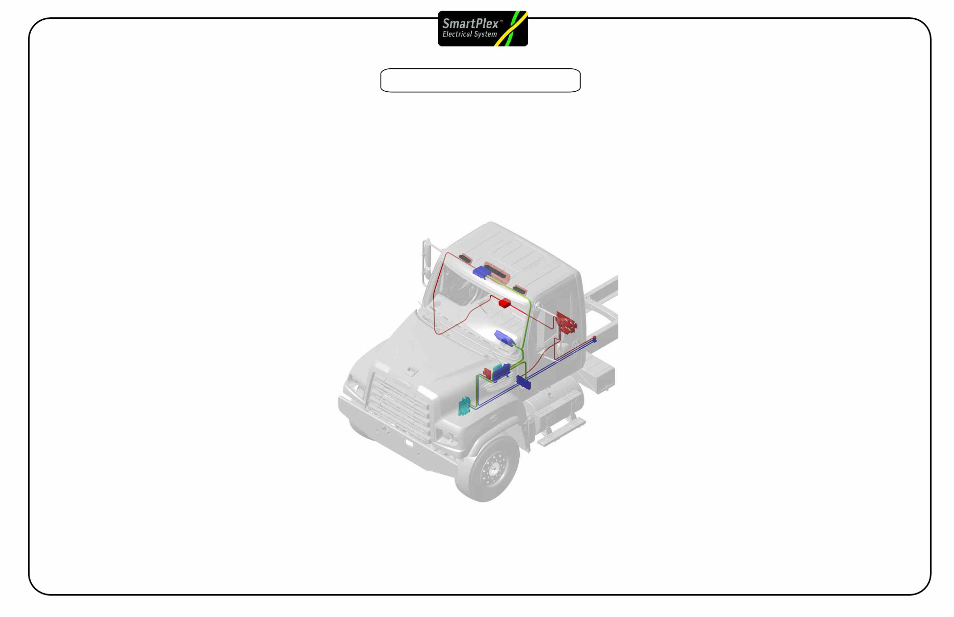
Electrical System Overview
2010 Smart Plex Electrical Body Builder Reference Page 1 Rev A
EPA 2010 Models
Electrical System Overview
EPA 2010 Models
Index
Page 1 Index
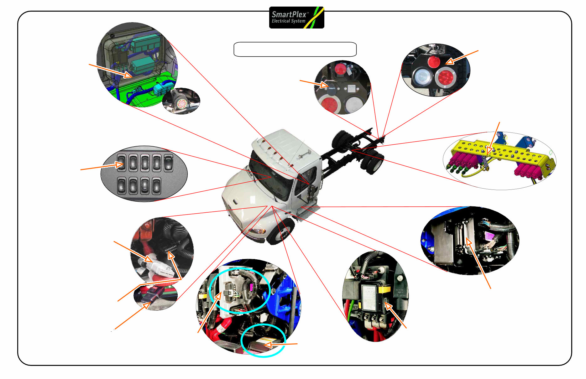
Page 2 Electrical Component Overview
Page 3 Electrical Harness Overview
Page 4 Electrical Power flow Overview
Page 5
Page 6
Page 7
Page 8
Page 9 Bulk Head Module (BHM)
Page 10 Bulk Head Module (BHM) Pin Detail
Page 11 Chassis Module (CHM)
Page 12
PNDB Power Net Distribution Box
Positive Disconnect Switch
Main Power Distribution Module (PDM)
PDM / VBAT Fuse Coverage
Chassis Module (CHM) Pin Detail
Page 13 Multiplexing System Backbone
Page 14 System Tap Points
Page 15 J1708 Gateway
Page 16 Low Current Smart Switches
Page 17 High Current Switches (Battery Hot)
Page 18 High Current Switch (BH) Schematics
Page 19 High Current Switches (Ignition Interlocked)
Page 20 High Current Switch (Ignition Interlocked) Schematics
Page 21 High Current Switch Label Options
Page 22 Body Builder Lighting Interface
Page 23 Body Builder PDM
Page 27 Trailer Electrical Schematics (Combination)
PTO Installation
Page 36 PTO PTO Controls
Page 37 PTO Air Schematics
Page 38 PTO Electrical Schematics
Page 39 Hybrid PTO Options
Page 40 Remote Start Stop Schematics
Page 41 VDR Prep Information (NFPA)
Page 42 SmartPlex VDR Connections
Page 24 Body Lighting Interface Schematics
Page 25 Trailer PDM
Page 26 Trailer Electrical Schematics (Seperate)
Page 28 Wired Rite Prep
Page 29 Wired Rite Schematic
Page 30 Wired Rite Trailer and Floor connections
Page 31 Tail Lights
Page 32 Tail Light Schematics
Page 33 Transmission Interface
Page 34 Engine Interface
Page 35
2010 Smart Plex Electrical Body Builder Reference Page #2 Rev A
Accessory Air
Valve Assembly (AAVA)
(Multiple Modules )
Body lighting
Interfaces
(Module 353, 296)
Dash Switches
(Module 329)
Tail Light
Configurations
(Module 294)
Trailer Interfaces
(Module 296, 297)
(Module )
Engine Interface
(Black Plug)
(Plugs may also
be frame located)
148, 163, 87L
Transmission
(Grey Plug)
(Plugs may also
frame located
Interfaces.
be
(Module , 34C)
Electrical Component Overview
EPA 2010 Models
2010 Smart Plex Electrical Body Builder Reference Page #3 Rev A
PNDB Power Net Distribution
Box (Module 33P/281/293)
Chassis Module
(CHM Under Cab)
(Module 335, 32K)
Power Distribution
(Module 285 PDM)
Bulk Head Module
(BHM)
(Module 32A)
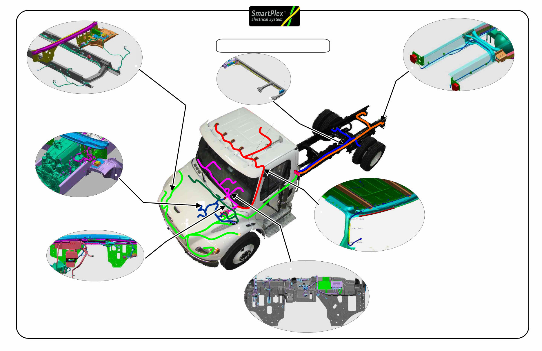
Electrical Harness Overview
FORWARD CHASSIS HARNESS Module
1) Connections to Bulkhead module and Underhood PDM
2) Connections to headlamps
3) Connections to side marker/turn lamps
4) Connections to Chassis Module
288
AFT CHASSIS HARNESS Module
1) Connections to Chassis Module
2) Connections to tail lamps
28A
MAIN CAB HARNESS Module
1) Connections to bulkhead connector
2) Connections to diagnostic connector (behind ignition switch)
3) Connections to CPC
4) Pass-thru connector to engine compartment
5) Gauge Cluster
6) HVAC unit and controler
7) Steering wheel horn and windshield wiper
320
OVERHEAD CAB HARNESS Module 287
1) Inline connection to Main cab Harness
(at bottom of A pillar)
2) Connections to Marker Lamps
3) Connections to Dome Lamp
FRONTWALL HARNESS Module 321
1) Connections to Bulkhead Module and Underhood PDM
2) Connection to Starter Mag Switch
3) Connection to Wiper Motor
4) Connection to the low coolant level sensor and horn (under surge tank)
5) Connection under cab to Washer pump and level switch
6) Pass-thru connector to Main Cab Harness and Powertrain Harness
POWERTRAIN HARNESS Module 286, 283
1) Connections to the Bulkhead
Module and Underhood PDM
ABS/AMU HARNESS Module 332
1) Connections to Forward chassis
harness and frame ground studs near
Chassis module
2) Connections to AMU (Mod 877 without ABS)
3) Connections to Wabco ABS ECU
4) Connections to rear combo valves
EPA 2010 Models
2010 Smart Plex Electrical Body Builder Reference Page #4 Rev A
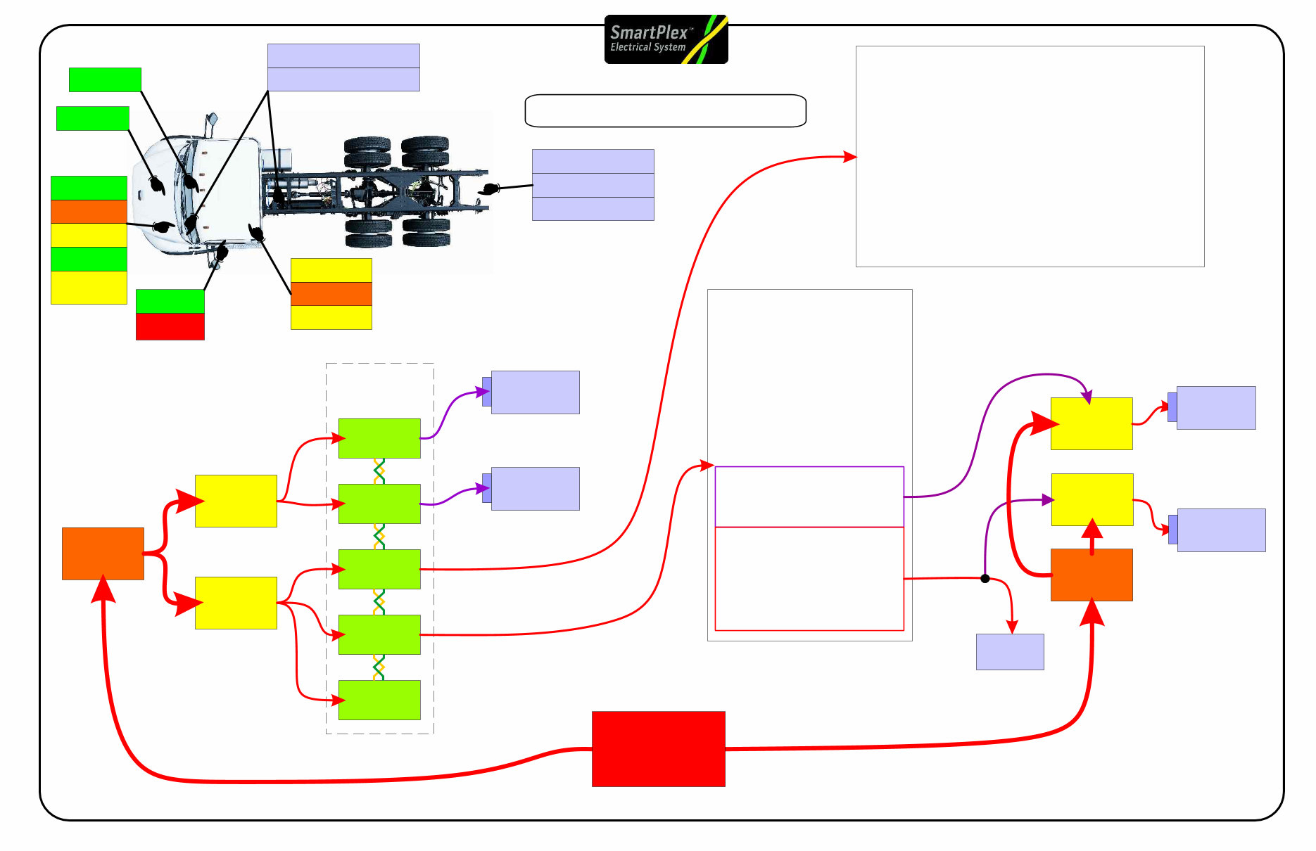
Electrical Power Flow Overview
EPA 2010 Models
Battery
Main PNDB
TCM
Trailer PDM
Tail Lights
BB PNDB
Body Lighting Conn
Transmission Connector
BB PDM
Trailer Connector
Engine Connector
Main PDM
BHM
Powertrain
PDM
ECM
ICU
CHM
C2-F Trailer Marker Relay
C2-H Trailer Turn Left Relay
C2-E Trailer Turn Right Relay
C2-A Trailer Power Relay
C2-D Trailer Stop Lamp Relay
Chassis Module Outputs
Bulkhead Module Outputs
B5.E - SPARE (Utility Light/Spotlight)
B4.M - SPARE (Utility Light/Spotlight)
B3.E - Horn
B5.F - Cigar Lighter Output
B5.H - Panel Lamps
B7.A1 - Panel Lamps (Smart Switch)
B5.G - SPARE (Ignition)
B6.A9 - Accessory (HVAC)
B6.A10 - Accessory (Radio)
B4.F - SPARE (Left Heated Mirror)
B4.E - SPARE (Right Heated Mirror)
B6.A8 - Ignition (VCU)
B2.K - Ignition (Engine)
B1.P - Ignition (ABS)
B5.A - Battery (Dome Lamps)
B7.A12 - Battery (Smart Switch)
B5.D - Instrument Cluster
B5.B - Dome Lamps Switched
B1.L - Left High Beam
B2.L - Ignition (Trans)
B1.F - Fuel Water Sensor Power
B3.F - Wiper High
B5.C - Clearance Lamps
B1.K - Tail/License Plate
B1.R - Left Low Beam
B3.H - Wiper Low
B3.G - Washer Pump
B2.M - AC Clutch
B4.B - Starter Relay (Crank)
/Trailer Relay
C3-A Optional Fuel Water Separator Heater
C4-C Left Park Lamp
C4-L Right Park Lamp
C4-D Left Marker Lamp
C4-M Right Marker Lamp
C3-N Turn Left Front/Side
C1-G Turn Left Rear
C3-R Turn Right Front/Side
C1-P Turn Right Rear
C1-A Left Backup Lamp
C1-J Right Backup Lamp
C1-H Backup Alarm
C3-L Right Low Beam
C4-K Right High Beam
C1-N Left Stop Lamp
C1-L Right Stop Lamp
C3-K Right DRL
C4-F Left DRL
C3-C Optional Fog/Road Lamps
C3-D Optional Fog/Road Lamps
C5-H AMU Solenoid #0
C5-J AMU Solenoid #1
C5-L AMU Solenoid #2
C5-M AMU Solenoid #3
ECM
TCM
BHM
CHM
ICU
BB
PNDB
Main
PNDB
Main
PDM
Powertrain
PDM
BB
PDM
Trailer
PDM
Battery
(296) Trailer
Connector
(353) Body
Lighting Conn
Engine
Connector
Transmission
Connector
(294) Tail
Lights
J1939
Multiplexed
Network
2010 Smart Plex Electrical Body Builder Reference Page #5 Rev A
PNDB Power Net Distribution Box
EPA 2010 Models
INSTALLATION WITHOUT
DISCONNECT SWITCH
INSTALLATION WITH
DISCONNECT SWITCH
Primary
Solenoid
for Cut off
Switch
Battery
Input
Primary Solenoid
Cut Off Switch
Connection
ATC Fuse
Output
ATC Fuses
MIDI Fuse
Output
Fuse Cover
and label
Power Net Distribution Box (PNDB)
The PNDB is a new power delivery for the
SmartPlex to deliver more consistent and better
protected power from the battery to the other components
on the truck.
The PNDB also has protected keep alive circuits that
maintain power even with the cutoff switch is in the off position.
The primary reason for this change is to provide power to the
2010 DEF purge system which drains urea from the delivery
system and prevents the system from freezing during cold
conditions.
The PNDB located at the front wall is equipped with three
MIDI fuses which supply power to the Main Power
Distribution Module. These fuse connections have been
relocated from the battery in 2010 to prevent corrosion
and improve the trucks reliability in severe conditions.
A secondary PNDB is available as an option for the body builder and
will be located with the trailer and bodybuilder PDM located in the cab
behind the drivers seat on day cabs or under the rear bench seat for
crew cab units.
designed
system
ATC -A
ATC -B
ATC -C
ATC -D
ATC Fuse output
keeps power on after
disconnect
Mating connector
23-13153-410
1
A
2
2
3
1
A
B
C
D
B
3
C
A
D
B
E
C
F
4
D
Battery Input
300 AMPS Max
AFTER TREATMENT ECU
EMERGENCY POWER
RADIO AND CLOCK
ALTERNATOR REMOTE SENSE
GROUND
X2 KEEP ALIVE
CIRCUIT
X1 SOLENOID
CONTROL
SIGNAL OFF
LED INDICATOR
SIGNAL ON
SIGNAL RETURN
GROUND
1
2
3
4
A
B
C
D
E
F
CONNECTOR
PIN DESCRIPTION
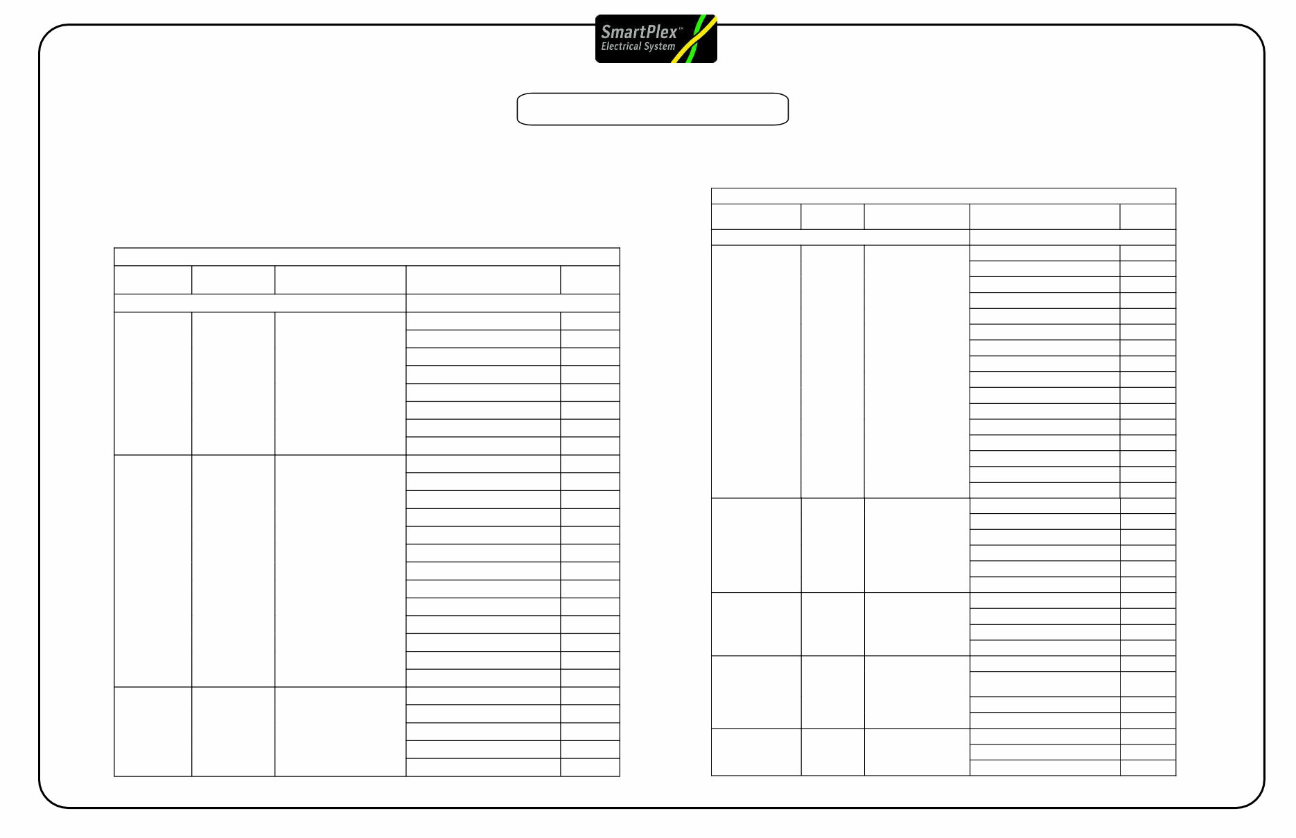
Fuse Description Function Rating Max. Fuse Allowed
ATC-A Keep Alive Power After Treatment ECU 30 AMPS 30 AMPS
ATC-B Keep Alive Power Emergency Power 20 AMPS 30 AMPS
ATC-C Keep Alive Power Radio and Clock 5 AMPS 30 AMPS
ATC-D Keep Alive Power Alternator Remote Sense 5 AMPS 30 AMPS
MIDI-1 (Fuse 1) High AMP Fuse Powertrain PDM 175 AMPS 200 AMPS
MIDI-2 (Fuse 2) High AMP Fuse PDM #2 125 AMPS 200 AMPS
MIDI-3 (Fuse 3) High AMP Fuse PDM #1 125 AMPS 200 AMPS
Solenoid Control
2010 Smart Plex Electrical Body Builder Reference Page #6 Rev A
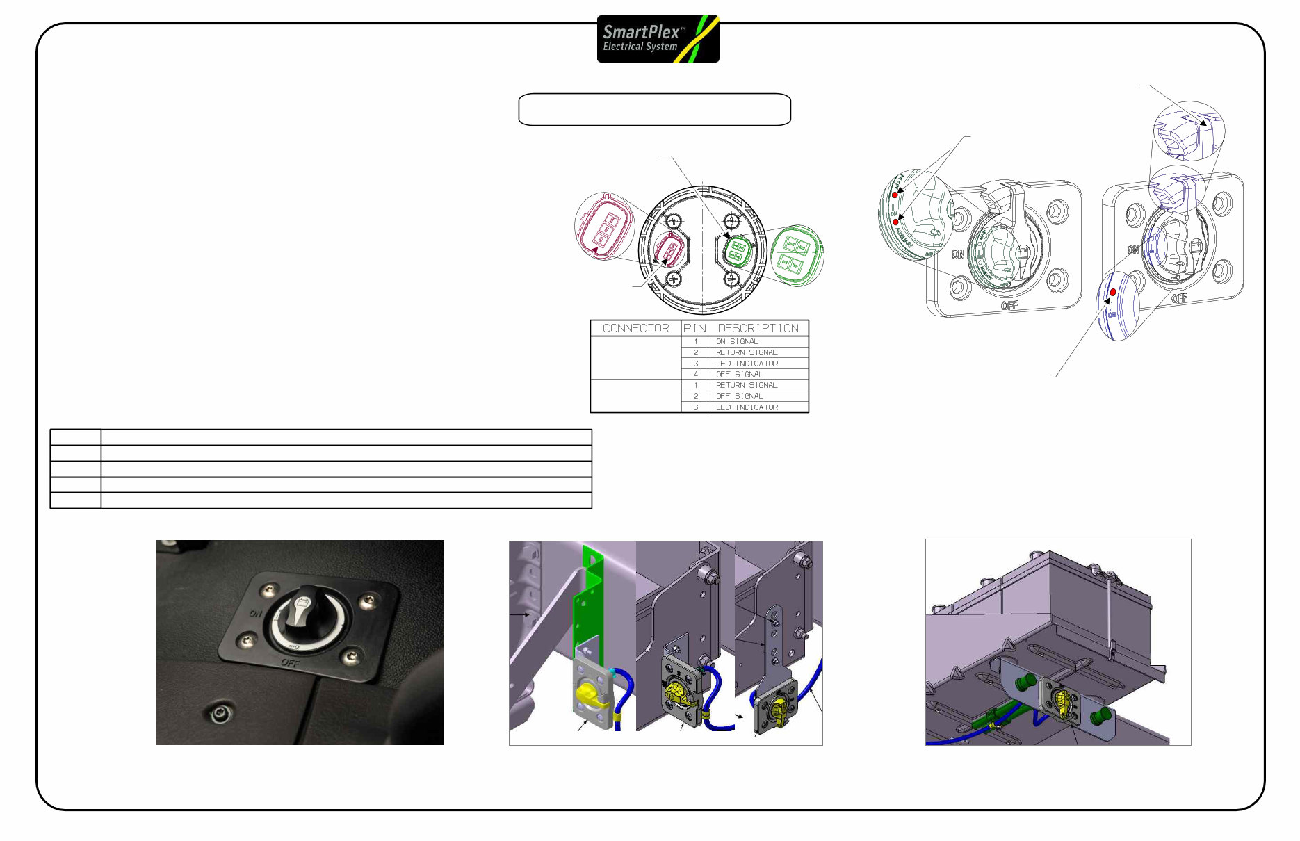
Positive Cutoff Switch
EPA 2010 Models
Battery Box Disconnect Switch Mounting
with box mounted air tanks
(brackets will vary depending on application)
293-061
In Cab Mounted Disconnect
Switch Mounting
293-058
Battery Box Mounting
without box mounted air tanks
293-001, 293-061
Disconnect Switch
Positive Disconnect Switch
The disconnect switch system for 2010 has been reconfigured
to provide better application coverage and offer two levels
of power disconnect based on the options ordered with the truck.
In cab disconnect switches will be offered in a locking or non locking
configuration.
Exterior battery mounted switches will be offered in the locking
configuration only.
Cutoff switches are equipped with red LED lights, which are
when power is on.
Trucks equipped with the body builder auxiliary power system
will have an additional LED light on the switch.
Note: Both PNDB units will be deactivated when the switch is in
the off position.
illuminated
Axillary Body Builder
Cutoff Switch
Standard
Cutoff Switch
Standard Power LED
Lockout Tab
Auxiliary Power
and Main Power
LED
Main Cab PNDB
Connector Plug
#23-13153-307
Body Builder PNDB
Connector Plug
#23-13662-401
1
3
2
1
4
2
3
293-057
293-061
293-060
293-058
NEGATIVE LOAD DISCONNECT W/CAB MTD DISCONNECT SWITCH
NEGATIVE LOAD DISCONNECT W/BATTERY BOX DISCONNECT SWITCH
POSITIVE LOAD DISCONNECT W/BATTERY BOX CTRL SWITCH W/LOCKING PROVISION
POSITIVE LOAD DISCONNECT W/CAB MTD CTRL SW W/LOCKING PROV MTD OB DR DEAT
POSITIVE LOAD DISCONNECT W/CAB MTD CONTROL SWITCH MTD OB DR SEAT
293-063
X2, Aux PNDB
X1, Main PNDB
2010 Smart Plex Electrical Body Builder Reference Page #7 Rev A
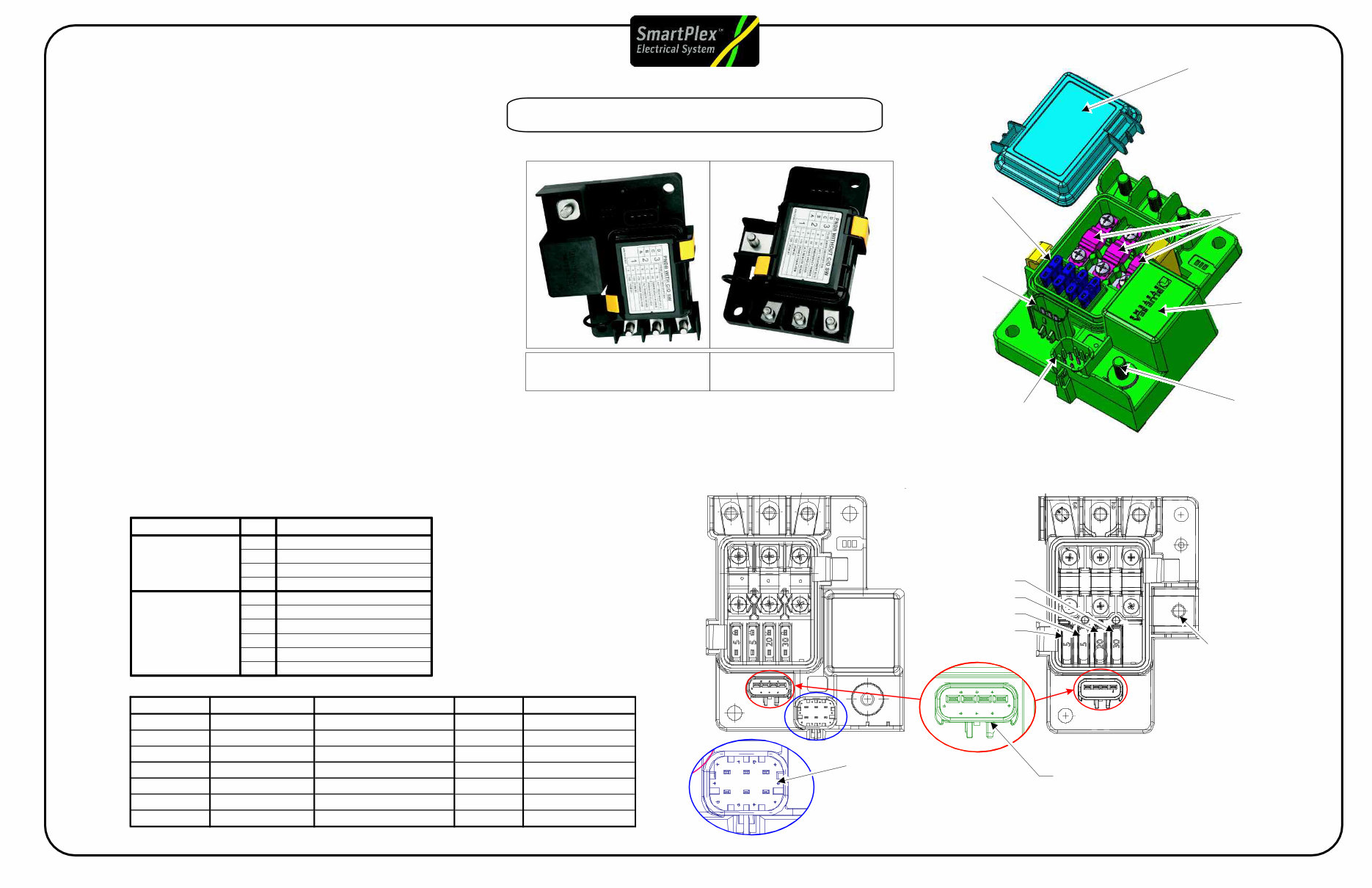
The main Power Distribution Module (PDM) distributes
battery power to the various control modules on the
vehicle.
The PDM contains mini fuses that
the power feed circuits to these modules.
For most trucks there will be spare fuse slots available
customers to add additional wiring to the truck after
purchased.
There are four plugs attaching to the module that supply
output connections.
Common spare fuse sockets are listed below but may
vary based on the options that have been requested.
Common Spare Fuse locations
F6, F10, F11, F14, F21, F23, F25, F26
protect
for
it is
A
B B
A
A
C
B
G
H E
G
D
C
B A D
B
F
C
D
H
H
G
G
D
C
H
E
E
F
Single Wire Output
found on
Plug in Pin G
Green
PDM Plugs
contain output
wires
PDM #1
(MIDI-3)
PDM # 2
(MIDI-2)
Engine Harness
Plug (Green)
Forward Chassis
Harness Plug (Blue)
Forward
Chassis
Harness
Plug
(Grey)
Front
Wall
Harness
Plug
(Black)
Main Power Distribution Module (PDM)
Power Distribution Module Fuse Specications*
Output MEGA Fuse
Connection Fuse Location
Primary Function
Fuse
Rating
Secondary Function
Fuse
Rating
Green A 1 F1
Spare {
Green B
Green H
1 F2 Blower Motor 30A {
{
{
{
{
2 F3 Spare
Spare
Spare
30A
Green G 2 F4 30A
30A
Black D 1
2
F5 Ignition Switch 5A { {
Black C 1
1
F6 Hydromax Relay
Gray F 1
1
F7 Bulkhead Module 30A { {
Green C 2
2
2
2
2
2
2
2
F8 ICU3-M2 10A {
{
{
Green D 2
1
1
1
1
1
1
F9 †
30A
Blue G
Green F
2
F10 Spare
Spare
{
{
{
{
{
{
{ {
Blue H F11 Spare { { {
Black H F12 Radio/Diagnostic 20A { {
Grey E F13 Chassis Module 30A { {
Black B F14 Spare { { {
Black A F15 Bulkhead Module 30A { {
Blue A F16
ABS ECU (pneumatic)
15A
ABS ECU (hydraulic) 25A
25A
Blue C F17 Chassis Module 30A { {
Blue B F18 Bulkhead Module 30A { {
Grey G F19 Chassis Module 30A { {
Black E F20 Bulkhead Module 30A { {
Black F
Grey H
Grey B
F21 Spare { { {
Black G
Blue E
Blue D
F22 Bulkhead Module 30A { {
F23 Spare {
{
{ {
Grey D F24
Hydraulic Pump and
Spare
Grey C F25 Spare { { {
Multiple Wire output
Pin A & B on Grey
Plug and Pin D
on Blue Plug
Grey A
F26 Spare
{ { {
Motor (hydraulic ABS)
VBAT 1 BHM
VBAT 2 BHM
VBAT 3 BHM
VBAT 4 BHM
VBAT 5 BHM
VBAT 1 CHM
VBAT 2 CHM
VBAT 3 CHM
F
VBAT
Fuse
Pin part number for harness connection
23-13213-120 TERM-FEMALE,(20-16) PAC12077411
23- -121 TERM- ,(14-12) PAC12129493 13213 FEMALE
23-13213-122 TERM-FEMALE,(10) PAC12077413
EPA 2010 Models
2010 Smart Plex Electrical Body Builder Reference Page #8 Rev A
Power Supply Fuses and Associated Outputs for the Bulkhead Module
BHM Power Input
BHM Power
Input Pin
Fuse Supplying BHM
Power Input
BHM Outputs Supplied
BHM
Power In Power Out
Battery (dome lamps) B5.A
Battery (smart switches) B7.A12
Ignition (VCU) B6.A8
Ignition (engine) B2.K
Ignition (ABS) B1.P
Ignition (trans) B2.L
Fuel Water Sensor Power B1.F
Dome Lamps Switched B5.B
Left Low Beam B1.R
A/C Clutch B2.M
Smart Switch 1 Indicator B7.B4
Smart Switch 2 Indicator B7.B8
Smart Switch 3 Indicator B7.A5
Smart Switch 4 Indicator B7.A9
Smart Switch 5 Indicator B7.B10
VBAT1 B3.D Fuse 22 (30A)
Battery (smart switch) B7.A12
Accessory (HVAC) B6.A9
Accessory (radio) B6.A10
Wake Up (instrument cluster) B5.D
Left High Beam B1.L
Wiper High B3.F
VBAT2 B4.G Fuse 20 (30A)
Horn B3.E
Wiper Low B3.H
Spare 8.0A HSD (ignition) B5.G
Panel Lamps B5.H
VBAT3 B1.N Fuse 18 (30A)
Panel Lamps (smart switch) B7.A1
Clearance Lamps B5.C
Tail Lamps/License Plate
Relay
B1.K*
Washer Pump B3.G
VBAT4 B4.K Fuse 15 (30A)
12V Output (cigar lighter) B5.F
Spare 8.5A (utility light/spotlight) B5.E / B4.M
Left Heated Mirror B4.F VBAT5 B1.J Fuse 7 (30A)
Right Heated Mirror B4.E
Power Supply Fuses and Associated Outputs for the Chassis Module
CHM Power
Input
CHM Power
Input Pin
Fuse Supplying CHM
Power Input
CHM Outputs Supplied
CHM
Power In Power Out
Right Low Beam C3.L
Turn Right Front/Side C3.R
Turn Right Rear C1.P
Right Stop Lamp C1.L
Left Stop Lamp C1.N
Right DRL C3.K
Fog/Road Lamps C3.C/C3.D
VBAT1 C4.P Fuse 19 (30A)
Trailer Turn Right C2.E
Left Park Lamp C4.C
Right Park Lamp C4.L
Left Marker Lamp C4.D
Right Marker Lamp C4.M
Trailer Marker Relay C2.F
Right High Beam C4.K
Left Backup Lamp C1.A
Right Backup Lamp C1.J
Backup Alarm C1.H
Turn Left Front/Side C3.N
Turn Left Rear C1.G
Left DRL C4.F
VBAT2 C3.J Fuse 17 (30A)
Trailer Turn Left C2.H
Fuel Water Separator Heater C3.A
AMU Solenoid 0 C5.H
AMU Solenoid 1 C5.J
AMU Solenoid 2 C5.L
VBAT3 C4.J Fuse 13 (30A)
AMU Solenoid 3 C5.M
Output Pin
Lamp/TrailerTail
Output Pin
VBAT Fuse System
BHM and CHM output pins are powered by multiple VBAT fuses
through the main PDM unit. If one of these fuses is
tripped or blown then all pins in the circuit will be affected.
For this reason seemingly unrelated issues can occur at the same
time if a fuse is overloaded and trips.
The lists below show which pins are controlled with the VBAT fuses.
SmartPlex PDM VBAT Fuse Coverage
EPA 2010 Models
Bulkhead Module BHM
Chassis Module CHM
2010 Smart Plex Electrical Body Builder Reference Page #9 Rev A
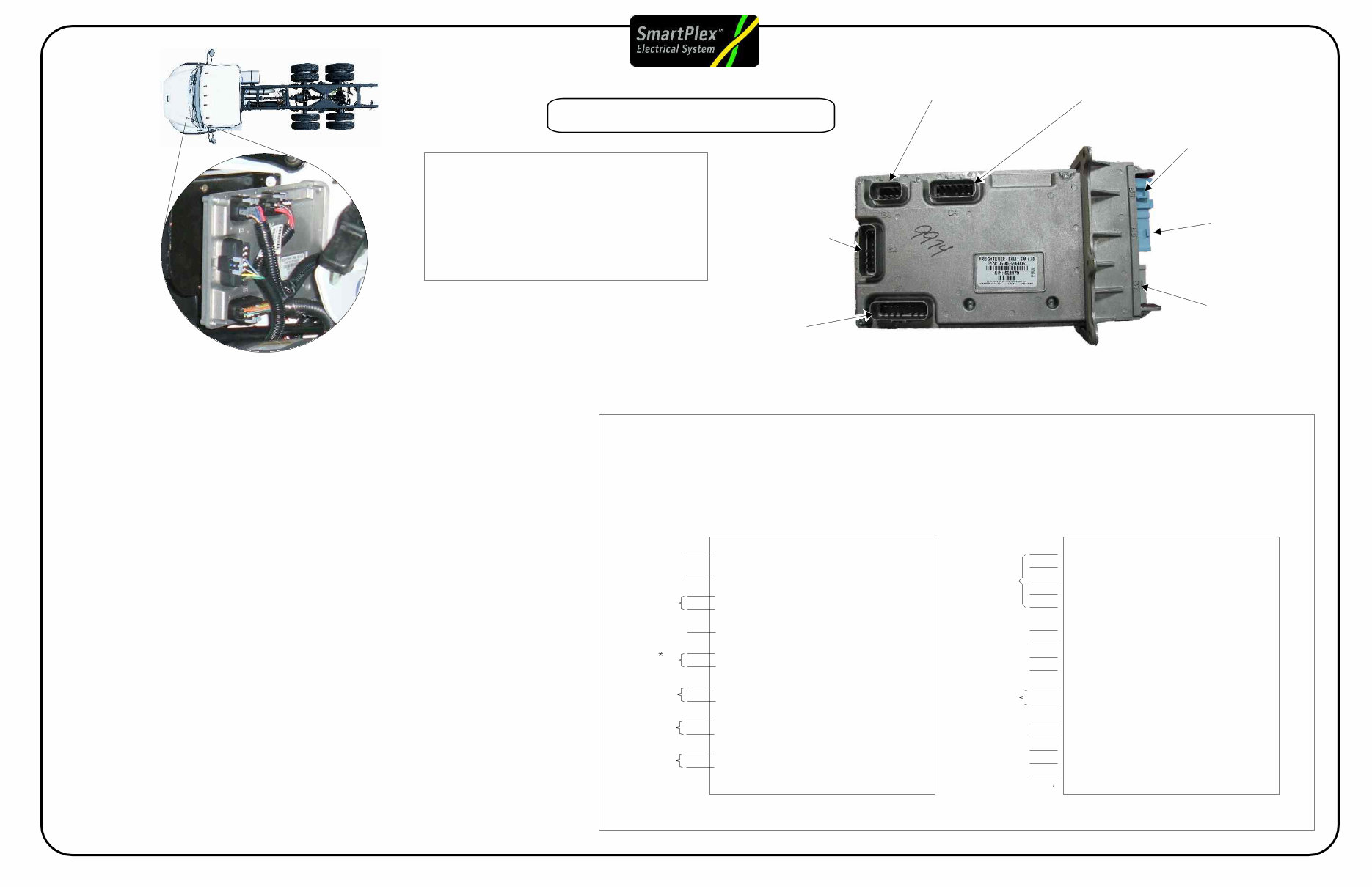
Bulk Head Module (BHM)
The Bulkhead Module (BHM)
The BHM is the primary command module for the electrical system.
The module controls the operation of the other component
the either directly or indirectly using messages sent over
The Bulkhead Module is mounted on the driver side of the front wall and connects
to the interior wiring through an opening in the front wall.
The BHM has four harness connections on the engine side of the front wall and
three harness connections to the cab interior.
The BHM Unit contains all system parameters and the unit controls power flow
and circuit protection to the various components of the electrical system.
The BHM unit can also support up to 5 smart switches. The BHM is
programable and can be changed and updated by flashing the unit through
service link.
Power supply for the BHM is supplied using VBAT fuses, which reside in the
main PDM (see page 3)
The BHM is programmable and the feature screen in service link can be used to
or add parameters to the BHM
SmartPlex
modules in
system the J1939 network.
SmartPlex
directly
change
B4 Front
Wall Harness
B3 Front
Wall Harness
B1 Forward Chassis
Harness
B2 Engine
Harness
B6 Dash
Harness
B5 Dash
Harness
B7 Dash
Harness
B5.E - SPARE (Utility Light/Spotlight)
B4.M - SPARE (Utility Light/Spotlight)
B3.E - Horn
B5.F - Cigar Lighter Output
B5.H - Panel Lamps
B7.A1 - Panel Lamps (Smart Switch)
B5.G - SPARE (Ignition)
B6.A9 - Accessory (HVAC)
B6.A10 - Accessory (Radio)
B4.F - SPARE (Left Heated Mirror)
B4.E - SPARE (Right Heated Mirror)
B6.A8 - Ignition (VCU)
B2.K - Ignition (Engine)
B1.P - Ignition (ABS)
B5.A - Battery (Dome Lamps)
B7.A12 - Battery (Smart Switch)
B5.D - Wake Up (Instrument Cluster)
B5.B - Dome Lamps Switched
B1.L - Left High Beam
B2.L - Ignition (Trans)
B1.F - Fuel Water Sensor Power
B3.F - Wiper High
B5.C - Clearance Lamps
B1.K - Tail/License Plate/Trailer Relay
B1.R - Left Low Beam
B3.H - Wiper Low
B3.G - Washer Pump
B2.M - AC Clutch
B4.B - Starter Relay (Crank)
6.7A
6.7A
6.7A
6.7A
6.7A
6.7A
Combined
6.7A
6.7A
6.7A
6.7A
6.7A
Combined
6.7A
Combined
6.7A
Combined
12A
Combined
12A
12A
Combined
12A
20A
Combined
- Bulkhead Module outputs have defined amperage limits.
- If higher loads are required, bulkhead module outputs should be used as signal
power in conjunction with a relay.
Key Bulkhead Module Outputs
Pin part numbers for harness connection
FEMALE
23-13212-122 TERM-FEMALE,(10) PAC15326004
Inside Cab Connections:
PAC12129494 TERM-FEMALE,(12-14)
PAC12034046 TERM-FEMALE,(16-18)
Outside Cab Connections:
23-13212-120 TERM-FEMALE,(18-16) PAC153047191
23-13212-121 TERM- ,(14-12) PAC15304720
EPA 2010 Models
2010 Smart Plex Electrical Body Builder Reference Page #10 Rev A
You're Reading a Preview
What's Included?
Fast Download Speeds
Online & Offline Access
Access PDF Contents & Bookmarks
Full Search Facility
Print one or all pages of your manual
$41.99
$54.99
Viewed 65 Times Today


Secure transaction
What's Included?
Fast Download Speeds
Online & Offline Access
Access PDF Contents & Bookmarks
Full Search Facility
Print one or all pages of your manual
$41.99
$54.99
The Freightliner M2 EPA 2010 Electrical Body Builder Reference Guide Manual provides an in-depth overview of the electrical components, harnesses, and power flow of the vehicle. It is an essential resource for both professional mechanics and DIY enthusiasts.
- Electrical Component Overview
- Electrical Harness Overview
- Electrical Power flow Overview
The manual covers detailed information on various modules and components including:
- Bulk Head Module (BHM)
- Bulk Head Module (BHM) Pin Detail
- Chassis Module (CHM)
- PNDB Power Net Distribution Box
- Positive Disconnect Switch
- Main Power Distribution Module (PDM)
- PDM / VBAT Fuse Coverage
- Chassis Module (CHM) Pin Detail
- Multiplexing System Backbone
- System Tap Points
- J1708 Gateway
- Low Current Smart Switches
- High Current Switches (Battery Hot)
- High Current Switch (BH) Schematics
- High Current Switches (Ignition Interlocked)
- High Current Switch (Ignition Interlocked) Schematics
- High Current Switch Label Options
- Body Builder Lighting Interface
- Body Builder PDM
- Trailer Electrical Schematics (Combination)
- PTO Installation
- PTO Controls
- PTO Air Schematics
- PTO Electrical Schematics
- Hybrid PTO Options
- Remote Start Stop Schematics
- M2 VDR Prep Information (NFPA)
- M2 VDR to M2 Connections
- Body Lighting Interface Schematics
- Trailer PDM
- Trailer Electrical Schematics (Separate)
- Wired Rite Prep
- Wired Rite Schematic
- Wired Rite Trailer and Floor connections
- Tail Lights
- Tail Light Schematics
- Transmission Interface
- Engine Interface
Whether you are working on the electrical system of a Freightliner M2 EPA 2010 as a professional or a DIY enthusiast, this manual is an invaluable resource for understanding and troubleshooting the vehicle's electrical components and systems.


