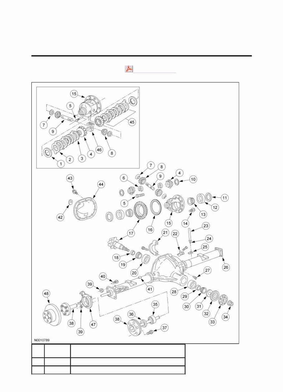
The axle assembly has the following features: An integral-type housing hypoid gear design (center of the pinion set below the centerline of the ring gear). The hypoid ring gear and pinion consists of a ring gear and an overhung drive pinion which is supported by 2 opposed tapered roller bearings. Drive pinion bearing preload is maintained by a drive pinion collapsible spacer on the drive pinion shaft and adjusted by the pinion nut. The axle housing consists of a cast center section with 2 steel tube assemblies and a stamped differential housing cover. The differential housing cover uses silicone sealant as a gasket. The differential pinion shaft is retained by a threaded differential pinion shaft lock bolt assembled to the differential assembly. The differential assembly is mounted in the axle housing between 2 opposing differential bearings that are retained in the axle housing by removable differential bearing caps. Differential bearing preload and differential ring and pinion backlash are adjusted by differential bearing shims located between the differential bearing cups and the axle housing. Axle identification is on an embossed metal tag bolted to the differential housing cover. For additional information, refer to Section 205 - 00 . 42 — Axle identification tag (part of 4001) 43 4346 Differential housing cover bolt (12 required) 44 4033 Differential housing cover 45 4947 Differential clutch pack 46 4214 Differential clutch spring 47 2C220 Rear wheel disc brake adapter (2 required) 48 2C206 Brake disc (2 required) Page 3 of 3 2005 F-150 Workshop Manual
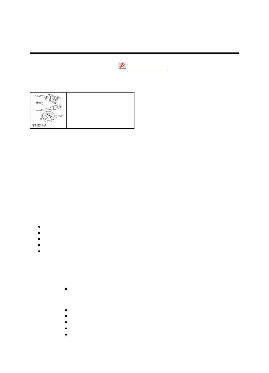
Rear Drive Axle and Differential Printable View (224 KB) Inspection and Verification The technician should have a thorough knowledge of driveline system operation and accepted general driveline guidelines to detect any problems. A gear driven unit will produce a certain amount of noise. Some noise is acceptable and audible at certain speeds or under various driving conditions. Certain conditions, such as road conditions and weather, will amplify normal vehicle noise. Certain rear axle and driveline concern symptoms are also common to the engine, transmission, rear wheel bearings and tire. For this reason, be sure the cause of the concern is in the axle before repairing or installing any axle components. The following is a guide to diagnose a driveline concern: Verify and document the customer concern. Perform a preliminary investigation. Road test the vehicle. Find the cause of the problem. Inspect the components. 1. Verify and document the customer concern. 1. When was it first noticed? 2. Did it appear suddenly or gradually? 3. Did anything unusual occur that would coincide with it or precede it? 4. Has the driveline system been repaired before or new components installed? Check the vehicle service record. Note any repairs other than driveline, such as brakes or suspension. 5. Are there any special conditions affecting the concern or will alter the concern? For example, road speed type of road drive mode temperature vehicle loaded or unloaded 6. Is the condition constant or intermittent? Can the concern be duplicated at any time? 7. Check for TSBs, SSM and OASIS messages. SECTION 205-02B: Rear Drive Axle/Differential — Ford 9.75-Inch Ring Gear 2005 F-150 Workshop Manual DIAGNOSIS AND TESTING Procedure revision date: 01/27/2005 Special Tool(s) Dial Indicator Gauge with Holding Fixture 100-002 (TOOL-4201-C) or equivalent Page 1 of 8 2005 F-150 Workshop Manual
2. NOTE: If the inspection reveals an obvious concern, repair the vehicle. Do a preliminary investigation. Visually inspect for obvious signs of damage. 1. Inspect the driveshaft: for build up of any foreign material. for damage, such as a bent tube or missing weights. U-joints or flex couplers for wear or damage. 2. Inspect the axle: for signs of leakage at the drain or fill plug, differential seal, vent or halfshaft seals. a plugged vent or vent tube will cause a leak. for damage, such as cracks, bent halfshafts or dented rear cover. for missing fasteners. 3. Inspect other suspect components/systems: inspect the halfshaft assemblies for damaged CV joints or torn CV boots inspect the suspension for broken springs, damaged shock absorbers and worn suspension bushings. inspect the rear brake components — lines, cables and calipers. inspect the tires; are they in good condition and do they match? 3. NOTE: A road test is necessary for any customer concern of noise or vibration. Road test the vehicle. 1. During the road test, use the following driving methods to diagnose the problem. Is the concern most noticeable: from a stop? on shifts from REVERSE to DRIVE? on turns? sweeping type turn. tight turn (to the stop). in DRIVE? accelerating the vehicle, definite throttle depression, applying engine torque? in CRUISE? maintain a constant speed with the throttle applied? in COAST? decelerating with the throttle closed? 2. Record when the concern occurs. Write down the kph (mph) range at which the noise/vibration occurs. 4. Find the cause of the problem. 1. Compare the inspection and road test results with the following chart. 2. Use the following diagnostic routine chart to identify the probable cause and know what corrective actions should be taken to repair the component/vehicle, and to prevent a reoccurrence. Diagnostic Routine Chart Condition Action · Fluid loss · GO to Diagnostic Routine — Fluid Loss · Noise louder on turns (sweeping turn) · GO to Diagnostic Routine — Noise Louder On Turns (Sweeping) · Axle noise (growl) a in tight turn · GO to Diagnostic Routine — Noise (Growl) In Tight Turn · Axle noise (chatter/shudder) a in tight turn, limited slip differential · GO to Diagnostic Routine — Noise (Chatter/Shudder) In Tight Turns, Limited Slip Differential · Axle noise (whine) a in all or more than · GO to Diagnostic Routine — Noise (Whine) Page 2 of 8 2005 F-150 Workshop Manual
Smoothly streamline automotive fixes with The Ultimate Ford USA Package, your comprehensive toolkit designed to elevate your Ford maintenance experience. This all-in-one resource features meticulous instructions for common repairs, such as replacing the water pump and calibrating the throttle body, ensuring you tackle these tasks with confidence and precision. Each guide is accompanied by high-quality visuals and expertly crafted walkthroughs that demystify the complexities of Ford vehicle servicing, making it accessible for DIY enthusiasts and seasoned mechanics alike. One standout benefit of The Ultimate Ford USA Package is the inclusion of exclusive tips directly from industry professionals, empowering you with insider knowledge that can save you both time and money.
NOTE: This is a sample. Your actual software manual may differ slightly.
Discover the Ultimate Ford Package, your comprehensive solution for all Ford models spanning from 1992 to 2013. This package covers all models within this time frame, ensuring a wide range of coverage.
Includes all models from 1992 - 2013, as listed here.
If your specific make and model is not listed, please reach out to us here.
Unlock a wealth of automotive knowledge with our workshop manuals and electronic parts catalogues, suitable for both professional mechanics and dedicated DIY enthusiasts. These manuals are trusted by main dealer mechanics worldwide and offer detailed information, easy-to-understand diagrams, and up-to-date instructions at a fraction of the expected price.
Additionally, the package includes a complete electronic parts catalogue for all Ford models, simplifying the process of finding the right part with clear diagrams and a user-friendly search function.
Please note: This manual is approximately 55 GB in size and is available in .OVA format, compatible with VirtualBox, a free and user-friendly platform compatible with Windows PC, Linux, and Mac. Comprehensive instructions are provided for a seamless experience.
Key features covered in this ultimate package include:
General Maintenance Tasks and Fault Finding
Strict Maintenance Operations
Troubleshooting
Servicing Fuel System
Heating and Air Conditioning
Steering
Safety Restraining Systems (Airbags)
Suspension and Forks
Engine and Transmission
Engine Install / Remove
Bodywork Repairs
Clutch Remove / Install
Cooling System
Exhaust System
Gearbox (Auto & Manual)
Braking System
Timing Chain Service
Wheels and Tyres
Suspension
Current Flow Diagrams / Wiring Diagrams
Workshop Repair Guides
General Electric
Running Gear
Power and Transmission
Plus Much More...
Don't miss this opportunity to elevate your automotive expertise, save money, and confidently tackle any repair or maintenance task. Order the Ultimate Ford Package today and experience the power of knowledge firsthand.