

2000-2002 Kawasaki Mule 2510 Diesel KAF950 UTV Service & Repair Manual
What's Included?
Fast Download Speeds
Online & Offline Access
Access PDF Contents & Bookmarks
Full Search Facility
Print one or all pages of your manual
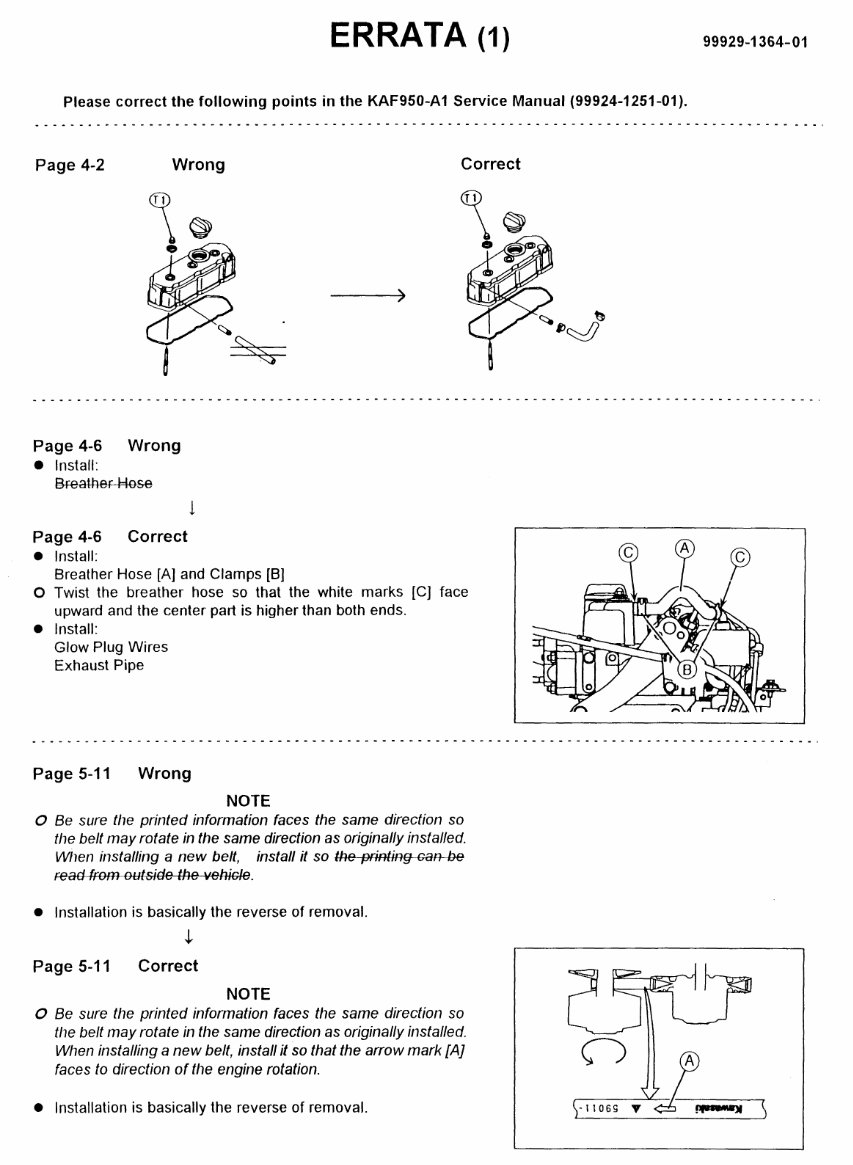
ERRATA (1)
Please correct the following points in the KAF950-A 1 Service Manual (99924-1251-01 ).
Page 4-2 Wrong Correct
Page 4-6 Wrong
• Install:
Breather Hose
l
Page 4-6 Correct
• Install:
Breather Hose [A] and Clamps [B)
0 Twist the breather hose so that the white marks [C) face
upward and the center part is higher than both ends.
• Install:
Glow Plug Wires
Exhaust Pipe
Page 5-11 Wrong
NOTE
0 Be sure the printed information faces the same direction so
the belt may rotate in the same direction as originally installed.
Wilen installing a new belt, install it so the printinf}-£aA--be
r:ead from outside the veRiGie.
• Installation is basically the reverse of removal.
,}
Page 5-11 Correct
NOTE
0 Be sure the printed information faces the same direction so
the belt may rotate in the same direction as originally installed.
When installing a new belt, install it so that the arrow mark [A]
faces to direction of the engine rotation.
• Installation is basically the reverse of removal.
99929-1364-01
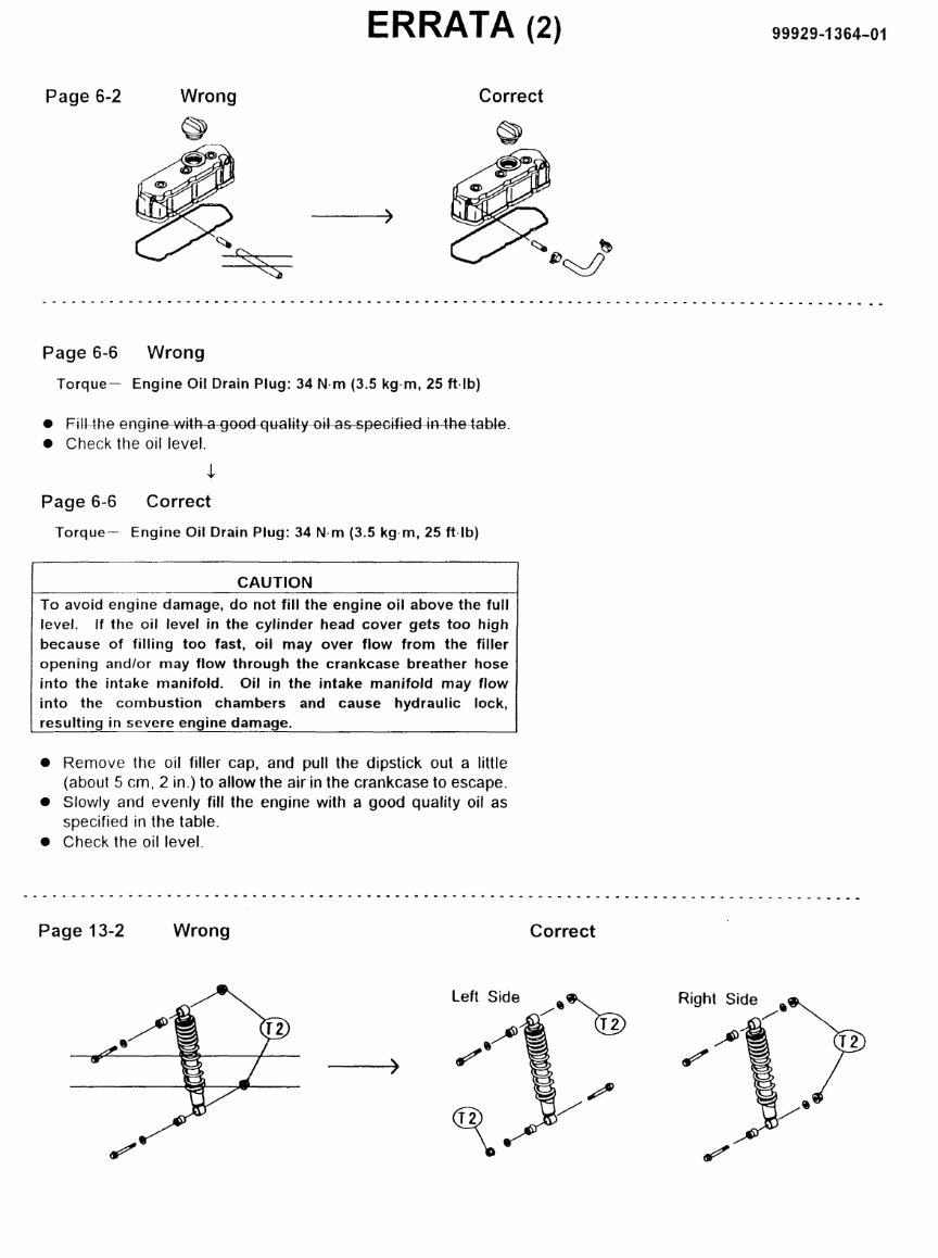
ERRATA (2)
Page 6-2 Wrong Correct
~
Page 6-6 Wrong
Torque- Engine Oil Drain Plug: 34 N·m (3.5 kg·m, 25 ft·lb)
• F~lt-the en§ine with a good quality--00-as--specified in the table.
• Check the oil level.
Page 6-6 Correct
Torque- Engine Oil Drain Plug: 34 N-m (3.5 kg·m, 25 ft-lb)
CAUTION
To avoid engine damage, do not fill the engine oil above the full
level. If the oil level in the cylinder head cover gets too high
because of filling too fast, oil may over flow from the filler
opening and/or may flow through the crankcase breather hose
into the intake manifold. Oil in the intake manifold may flow
into the combustion chambers and cause hydraulic lock,
resulting in severe engine damage.
• Remove the oil filler cap, and pull the dipstick out a little
(about 5 em. 2 in.) to allow the air in the crankcase to escape.
• Slowly and evenly fill the engine with a good quality oil as
specified in the table.
• Check the oil level.
99929-1364-01
----------------------------------------·-----------------------------------------------
Page 13-2 Wrong
)
Correct
Left Side
Right Side e
/
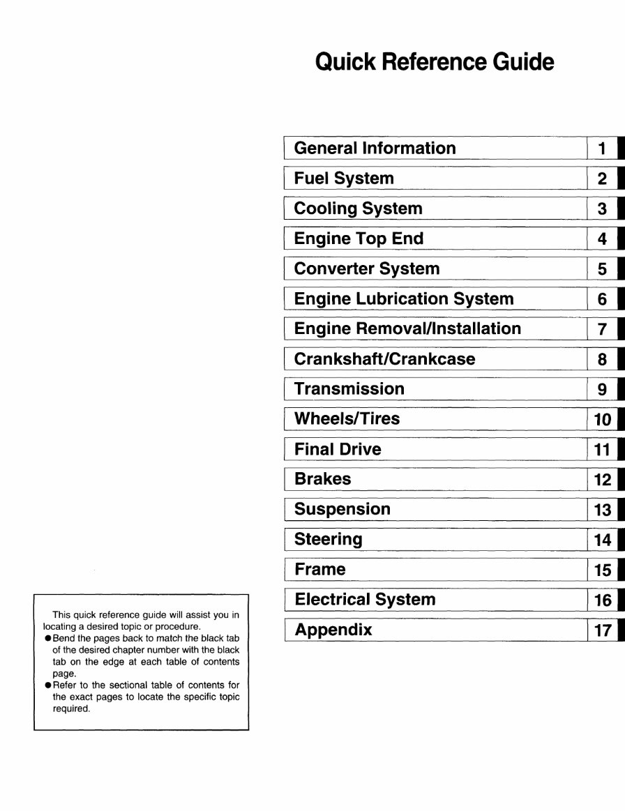
This quick reference guide will assist you in
locating a desired topic or procedure.
• Bend the pages back to match the black tab
of the desired chapter number with the black
tab on the edge at each table of contents
page.
• Refer to the sectional table of contents for
the exact pages to locate the specific topic
required.
Quick Reference Guide
General Information
1 I
Fuel System
Cooling System
Engine Top End
Converter System
s I
Engine Lubrication System
s I
[}_ngine Removal/Installation
Crankshaft/Crankcase
a I
Transmission
Wheels/Tires
Final Drive
Brakes
Suspension
Steering
Frame
Electrical System
Appendix
MULE2510
DIESEl
Utility Vehicle
Service Manual
©Kawasaki Heavy Industries. Ltd., 1999 First Edition (1) : Oct. 14, 1999 (M)
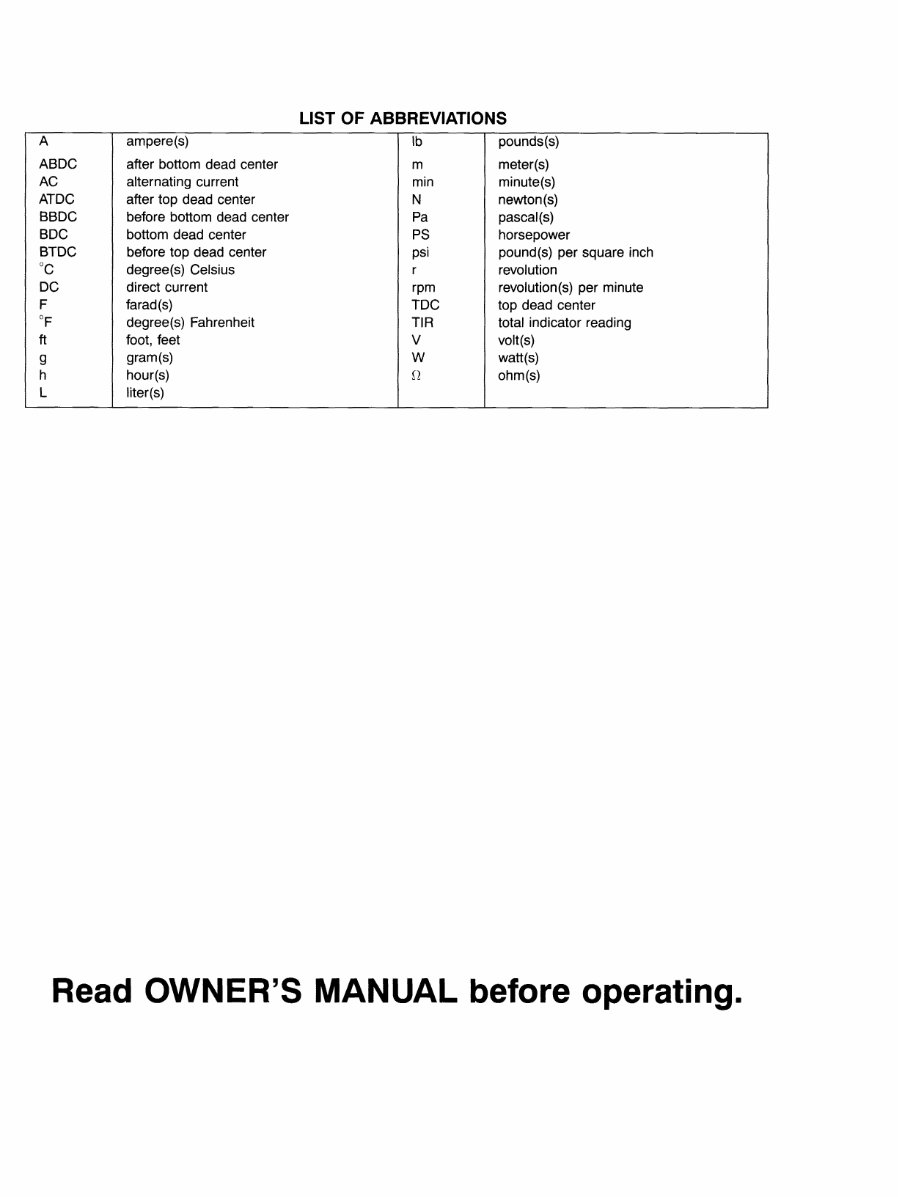
LIST OF ABBREVIATIONS
A ampere(s) lb pounds(s)
ABDC after bottom dead center m meter(s)
AC alternating current min minute(s)
ATDC after top dead center N newton(s)
BBDC before bottom dead center Pa pascal(s)
BDC bottom dead center PS horsepower
BTDC before top dead center psi pound(s) per square inch
oc
degree(s) Celsius r revolution
DC direct current rpm revolution(s) per minute
F farad(s) TDC top dead center
OF
degree(s) Fahrenheit TIR total indicator reading
ft foot, feet v volt(s)
g gram(s) w watt(s)
h hour(s) n ohm(s)
L liter(s)
Read OWNER'S MANUAL before operating.
EMISSION CONTROL INFORMATION
To protect the environment in which we all live, Kawasaki has incorporated crankcase emission (1) and exhaust emission
(2) control systems in compliance with applicable regulations of the United States Environmental Protection Agency and
California Air Resources Board.
1. Crankcase Emission Control System
A sealed-type crankcase emission control system is used to eliminate blow-by gases. The blow-by
gases are led to the breather chamber through the crankcase to the intake manifold.
Oil is separated from the gases while passing through the inside of the breEither chamber from the
crankcase, and then returned to the bottom of the crankcase.
2. Exhaust Emission Control System
The exhaust emission control system applied to this engine family is engine modifications that consist
of a modified injection pump and injection timing characteristics.
The fuel system has been calibrated to provide lean air/fuel mixture characteristics, with a suitable air
cleaner and exhaust system.
A maintenance free injection system provides the most appropriate injection timing and helps maintain
a thorough combustion process within the engine which contributes to a reduction of exhaust pollutants
entering the atomosphere.
The Clean Air Act, which is the Federal law covering motor vehicle pollution, contains what is commonly referred to as
the Act's "tampering provisions."
"Sec. 203(a) The following acts and the causing thereof are prohibited ...
(3)(A) for any person to remove or render inoperative any device or element of design installed on or
in a motor vehicle or motor vehicle engine in compliance with regulationfS under this title prior to
its sale and delivery to the ultimate purchaser, or for any manufacturer or dealer knowingly to
remove or render inoperative any such device or element of design after such sale and delivery
to the ultimate purchaser.
(3)(8) for any person engaged in the business of repairing, servicing, selling, l~asing, or trading motor
vehicles or motor vehicle engines, or who operates a fleet of motor vehicles knowingly to remove
or render inoperative any device or element of design installed on or in a motor vehicle or motor
vehicle engine in compliance with regulations under this title following its sale and delivery to the
ultimate purchaser ... "
(Continued on next page.)
NOTE
u The phrase "remove or render inoperative any device or element of design" has been generally
interpreted as follows:
1. Tampering does not include the temporary removal or rendering inoperative of devices or
elements of design in order to perform maintenance.
2. Tampering could include:
a. Maladjustment of vehicle components such that the emission standards are exceeded.
b. Use of replacement parts or accessories which adversely affect the performance or
durability of the vehicle.
c. Addition of components or accessories that result in the vehicle exceeding the standards.
d. Permanently removing, disconnecting, or rendering inoperative any component or element
of design of the emission control systems.
WE RECOMMEND THAT All DEALERS OBSERVE THESE PROVISIONS OF FEDERAL LAW, THE VIOLATION OF
WHICH IS PUNISHABLE BY CIVIL PENALTIES NOT EXCEEDING $10,000 PER VIOLATION.
PLEASE DO NOT TAMPER WITH NOISE CONTROL SYSTEM
(US Model only)
To minimize the noise emissions from this product, Kawasaki has equipped it with effective inta.ke and exhaust silencing
systems. They are designed to give optimum performance while maintaining a low noise level. Please do not remove
these systems, or alter them in any way which results in an increase in noise level.
Foreword
This manual is designed primarily for use by trained
mechanics in a properly equipped shop. However, it
contains enough detail and basic information to make
it useful to the owner who desires to perform his own
basic maintenance and repair work. A basic knowledge
of mechanics, the proper use of tools, and workshop
procedures must be understood in order to carry out
maintenance and repair satisfactorily. Whenever the
owner has insufficient experience or doubts his ability to
do the work, all adjustments, maintenance, and repair
should be carried out only by qualified mechanics.
In order to perform the work efficiently and to avoid
costly mistakes, read the text, thoroughly familiarize
yourself with the procedures before starting work, and
then do the work carefully in a clean area. Whenever
special tools or equipment are specified, do not use
makeshift tools or equipment. Precision measurements
can only be made if the proper instruments are used,
and the use of substitute tools may adversely affect safe
operation.
For the duration of the warranty period, we rec-
ommend that all repairs and scheduled maintenance be
performed in accordance with this service manual. Any
owner maintenance or repair procedure not performed in
accordance with this manual may void the warranty.
To get the longest life out of your vehicle:
• Follow the Periodic Maintenance Chart in the Service
Manual.
• Be alert for problems and non-scheduled maintenance.
• Use proper tools and genuine Kawasaki vehicle parts.
Special tools, gauges, and testers that are necessary
when servicing Kawasaki vehicles are introduced by
the Special Tool Catalog or Manual. Genuine parts
provided as spare parts are listed in the Parts Catalog.
• Follow the procedures in this manual carefully. Don't
take shortcuts.
• Remember to keep complete records of maintenance
and repair with dates and any new parts installed.
How to Use This Manual
In preparing this manual, we divided the product into
its major systems. These systems became the manual's
chapters. All information for a particular system from
adjustment through disassembly and inspection is located
in a single chapter.
The Quick Reference Guide shows you all of the
product's system and assists in locating their chapters.
Each chapter in turn has its own comprehensive Table of
Contents.
The Periodic Maintenance Chart is located in the
General Information chapter. The chart gives a time
schedule for required maintenance operations.
If you want engine oil information, for example, go to
the Periodic Maintenance Chart first. The chart tells you
how frequently to change the oil. Next, use the Quick
Reference Guide to locate the Engine Lubrication System
chapter. Then, use the Table of Contents on the first page
of the chapter to find the Engine Oil section.
Whenever you see these WARNING and CAUTION
symbols, heed their instructions! Always follow safe
operating and maintenance practices.
A WARNING
This warning symbol identifies special instruc-
tions or procedures which, if not correctly fol-
lowed, could result in personal injury, or loss of
life.
CAUTION
This caution symbol identifies special instruc-
tions or procedures which, if not strictly ob-
served, could result in damage to or destruction
of equipment.
This manual contains four more symbols (in addition to
WARNING and CAUTION) which will help you distinguish
different types of information.
NOTE
o This note symbol indicates points of particular in-
terest for more efficient and convenient operation.
• Indicates a procedural step or work to be done.
0 Indicates a procedural sub-step or how to do the work
of the procedural step it follows. It also precedes the
text of a NOTE.
*Indicates a conditional step or what action to take based
on the results of the test or inspection in the procedural
step or sub-step it follows.
In most chapters an exploded view illustration of the
system components follows the Table of Contents. In
these illustrations you will find the instructions indicating
which parts require specified tightening torque, oil, grease
or a locking agent during assembly.
GENERAL INFORMATION 1-1
General Information
Table of Contents
Before Servicing ......................................................... ,. ........................................................................................................ 1-2
Model Identification ................................................................................................. ,. ............................................................. 1-4
General Spec1ifications ................................................................................................ ,. .......................................................... 1-5
Periodic Maintenance Chart . ............................................................................................................................................... 1-7
Technicalllnlformation- Fuel1 Injection System Components ............................................................................................... 11-9
Torque and Locking Agent .......................................................................................... ,. .. ,. .................................................... 1-10
Special Tools, Sealant . ................................................................................ ,. ....................................................................... 1-14
Cable, Wire, and Hose Routing ....................................................................................... ,. ................................................ 1-19
You're Reading a Preview
What's Included?
Fast Download Speeds
Online & Offline Access
Access PDF Contents & Bookmarks
Full Search Facility
Print one or all pages of your manual
$31.99
$41.99
Viewed 59 Times Today


Secure transaction
What's Included?
Fast Download Speeds
Online & Offline Access
Access PDF Contents & Bookmarks
Full Search Facility
Print one or all pages of your manual
$31.99
$41.99
Get your hands on the comprehensive repair manual for the 2000-2002 Kawasaki Mule 2510 diesel UTV. This manual covers everything from complete tear down and rebuild to pictures and part diagrams, torque specs, maintenance, troubleshooting, and more. With 334 pages, it's a valuable resource for both professional mechanics and DIY enthusiasts.
This manual features clickable chapters and is searchable, making it easy to locate the information you need. There are no restrictions on printing or saving/burning to disc, providing you with convenient access to the manual.
For a wide range of Kawasaki Mule manuals, simply copy and paste this link into your browser:
http://www.tradebit.com/filesharing.php/search/0/mule/0/1/58622


