1993-2003 Kawasaki Mule 2500/2510/2520 Service & Repair Manual
What's Included?
Lifetime Access
Fast Download Speeds
Online & Offline Access
Access PDF Contents & Bookmarks
Full Search Facility
Print one or all pages of your manual
Kawasaki Mule 2500/2510/2520 service manual 1993-2003 This manual is comprised of a base manual for the Kawasaki Mule 2510/2520, along with a supplement manual to make it relevant for the Mule 2500. Kawasaki service manuals sometimes utilize this build-on-earlier models method when two models are similar to each other. Use the links below or the bookmarks to the left to get to the manual that covers your model. Kawasaki Mule 2510/2520 base manual Kawasaki Mule 2500 supplement manual
PLEASE DO NOT TAMPER WITH NOISE CONTROL SYSTEM (US Model only) To minimize the noise emissions from this product, Kawasaki has equipped it with effective intake and exhaust silencing systems. They are designed to give optimum performana, while maintaining a low noise level. Please do not remove these systems, or alter them in any which results in an increase in noise level. LIST OF ABBREVIATIONS A ampere(s) Ib pound(s) ABOC after bottom dead center m meter(s) AC alternating current min minute(s) ATOC after top dead center N newton(s) BBOC before bottom-dead center Pa pascal(s) BOC bottom dead center PS horsepower BTOC before top dead center psi pound(s) per square inch "C degree(s) Celsius r revolution DC direct current rpm revolution(s) per minute F farad(s) TOC top dead center "F degree(s) Fahrenheit TIR total indicator reading ft foot, feet V volt(s) g gram(s) W watt(s) h hour(s) 0 ohm(s) L liter(s) Read OWNER'S MANUAL before operating.
Foreword This manual is designed primarily for use by trained mechanics in a properly equipped shop. However, it contains enough detail and basic information to make it useful to the owner who desires to perform his own basic maintenance and repair work. A basic knowledge of mechanics, the proper use of tools, and workshop procedures must be understood in order to carry out maintenance and repair satisfactorily. Whenever the owner has "insufficient experience or doubts his ability to do the work, all adjustments, maintenance, and repair should be carried out only by qualified mechanics. In order to perform the work efficiently and to avoid costly mistakes, read the text thoroughly familiarize yourself with the procedures before starting work. and then do the work carefully in a clean area. Whenever special tools or equipment are specified, do not use makeshift tools or equipment. Precision measurements can only be made if the proper instruments are used, and the use of substi- tute tools may adversely affect safe operation. For the duration of the warranty period, we recommend that all repairs and scheduled maintenance be performed in accordance with this service manual. Any owner maintenance or repair procedure not performed in accordance with this manual may void the warranty. To get the longest lile out of your vehicle: • Follow the Periodic Maintenance Chart in the Service Manual. .Be alert for problems and non-scheduled mainte- nance. • Use proper tools and genuine Kawasaki vehicle parts. Special tools, gauges, and testers that are necessary when servicing Kawasaki vehicles are introduced by the Special Tool Catalog or Manual. Genuine parts provided as spare parts are listed in the Parts Catalog. .Follow the procedures in this manual carefully. Don't take shortcuts. • Remember to keep complete records of mainte- nance and repair with dates and any new parts installed. How to Use this Manual In preparing this manual, we divided the product into its major systems. These systems became the manual's chapters. All information for a particular system from adjustment through disassembly and inspection is located in a single chapter. The Quick Reference Guide shows you aU of the product's system and assists in locating their chapters. Each chapter in tum has its own compre- hensive Table of Contents. The Periodic Maintenance Chart is located in the General Information chapter. The chart gives a time schedule for required maintenance operations. If you want spark plug information, for example, go to the Periodic Maintenance Chart first. The chart tells you how frequently to clean and gap the plug. Next, use the Quick Reference Guide to locate the Electrical System chapter. Then, use the Table of Contents on the first page of the chapter to find the Spark Plug section. Whenever you see these WARNING and CAUTION symbols, heed their instructions! Always follow "safe operating and maintenance practices. , ... WARNING This warning symbol identifies special instructions or procedures which, if not correctly followed, could result in personal injury, or loss of life. CAUTION This caution symbol identifies special instructions or procedures which, if not strictly observed, could result in damage to or destruction of equipment.
This manual contains four more symbols (in addition to WARNING and CAUTION) which will help you distinguish different types of infonnation. NOTE e This note symbol indicates points of partic- ular interest for more efficient and convenient operation. • Indicates a procedural step or work to be done. e Indicates a procedural sub-step or how to do the work of the procedural step it follows. It also precedes the text of a NOTE. * Indicates a conditional step or what action to take based on the results of the test or inspection in the procedural step or sub-step it follows. In most chapters an exploded view illustration of the system components follows the Table of Contents. In these illustrations you will find the instructions indicating which parts require specifi~ tightening torque, oil, grease or a locking agent during assembly.
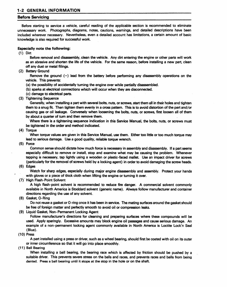
1-2 GENERAl INFORMATION Before Servicing Before starting to service a viehicle, careful reading of the appliicablesection is recommended to eliminate unnecessary work. Photographs, diagrams, notes, cautions, warnings, and detailed descriptions have been included wherever necessary. Nevertheless, even a detailed account has limitations, a certain amount of ba.sic knowledge is also required for suocessful WOlrk. Especially note the following: (1) Dirt Before removal and disassembly, clean the vehicle. Any dirt ,entering the ,eng.ine or other parts will work as an abrasive and shorten the life of the vehicle. For the same reason, before installing a new part, clean off any dust or metal filings. (2) Battery Ground Remove the ground (-) lead from the battery before performing any disassembly operations on the vehicle. This prevents: (a) the possibility of accidentally tuming the engine over while partiaUy disassembled. (b) sparks at electrical connections which wiUoccur when they a.re disconnected. (c) damage to electrical parts. (3) Tightening Sequence Generally, when installing a part with several bolts, nuts, or screws, start them all .in their holes and tighten them to a snug fit. Then tighten them evenly in a cross pattern. This is to avoid distortion of the part and/or causing ,gas or oil leakage. Conversely when loosening the bolts, nuts, or screws, first loosen all of them by about a quarter of turn and then remove them. Where there is a tightening sequence indication in this Service Manual, the bolts, nuts, or screws must be tightened in the order and method indicated. (4) Torque When torque values are ,given in this Service Manual, use th,em. Either too little or too much torque may lead to seri,ous damage. Use a good quality, reiliable torque wrench. (5) Force Common sense· should dictate how much fo~ce is necessary in assembly and disassembly. If a part seems especially difficult to remove or install, stop and examine what may be causing the problem. Whenever tapping is necessary, tap lightly using a wooden or plastic-faced mallet. Use an :impact driver for screws (particularly for the removal of screws held by a locking agent) iii order to avoid damaging the screw heads. (6) Edges. Watch for sharp edges, especia:11y during major engine disassembly and assembly. Protect your hands with gloves or a piece of thick cloth when lifting the engine or turning it over. (7)' High Flash-Point Solvent A high flash-point solvent is recommended to reduce fire danger. A commerc.ialsolvent commonly avail'ab/e in North America is Stoddard solvent (generic name). Always follow manufacturer and container directions regarding. the use of any solvent. (8) Gasket, O-Ring 00 not reuse a gasket or O-,ring once it has been in service. The mating surfaces around the gasket should be free of foreign matter and perfectly smooth to avoid oil or compression leaks. ('9) Liquid Gasket, Non-Permanent Locking Agent Follow manufacturer'S directions toir cleaning and prepa.ring surfaces where these compounds will be used. Apply sparingly. Excessive amounts may block engine oil passages and cause serious damage. An example of a non-pennanent locking agent commonly available in North America is Loctite Lock'n Seal (Blue). (10) Press A part installed using a press or driver, such as a wheel bearing, should first be coated with oil on .its outer or inner circumference so that it will go into place smoothly. (11) Ball Bearing When installing a ba,1I bearing,. the bearing race which is affected by friction should be pushed by a suitable driver. This prevents severe stress on the balls and races, and prevents races and balls from being dented. .Press a ban bearing until it stops at the stop in the hole or on the shaft.
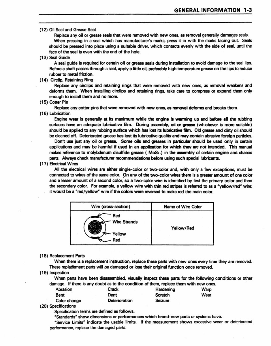
GENERAL INFORMATION 1-3 (12) Oil Seal and Grease Seal Repla,ce any oil or grease seals that were removed with new ones, as removal generally damages seals. When pressing ina seal which has manufacturer's marks, press it in with the marks facing out. Seals should be pressed into place using a suitable driver, which contacts evenly with the side of seal, until the face of the sea.1 is even with the end of the hOile ... (13) Seal Guide A seal guide is required for oertain oil. or grease seals during installation to avoid damage to the sea.llips. Before a shaft passes through a seal, apply a little oil. preferably high temperature grease on the lips to reduce rubber to metal friction. (14) Circlip, Retaining Ring R,eplace any circlips and retaining rings that were removed with new ones, as removal weakens and defonns them. When installing circlipsand retaining rings. take care to compress or expand them only enough to install,1 thernand no more. (15) Cotter Pin Replace any cotter pi.ns that were removed with new ones,. asl'8ll1CMll defoinns and breaks them. (16) Lubrication Engine wear is general,1y at its maximum while the engine isw.ming up and before all the rubbing surfaces have an adequatelubricatiw film. During assembly. oil or gr8IIS8 (whichever is more .suitable) should be applied to .any rubbing surface which has lost its lubrica:tMI film. Old grease and dirty oil should be cleaned off. Deteriorated grease has kJst its lubricatiw quality and may cootain abmive foreign particles .. Don't use just any oil or grease. Some oils and greases in panicut. should be uSed only in.cerrain applications ,and may be han'nful if used in an application fo,r which they are not intended. This manl,lal makes reference to molybdenuml disulfide grease ( MoS2.) in the assembly of certain engiineand ,chassis parts. Always check manufacturer recommendations before using such special lubricants. (17) Electrical Wires All the electrical wires are either single-colloror two-color and. with only a few exceptions, must be connected to wires of the same colior. On any of the two-color wires there is a greater amount of one color and a lesser amount of a second color, so a two-c910r wire is identified by first the primary co!lor and then the secondary color. For example, a yellow wire with thin red stripes is referred to as a "yellow Ired" wire; it would be a "red/yellow" wire if the colors were reversed to ma!ke Ired the main color. (18) Replacement Parts Wire (cross-section) Red Wire Strancls Yellow Red Name of Wire Color Yellow/Red When there is a replacement in$1J'Uction, replace these parts with new ones 'every time they are removed. These repla6"ernent parts will be damaged or lose their original function once removed. (19) Inspection When parts have been disassembted, visua:.11y inspect these parts for the following conditions or other damage. If there is any doubt as to the condition of them, replacethern with new ones. Abrasion Crack Hardening Warp Bent Dent Scratch Wear Color change Deterioration Seizure (20) Specificatio,ns Specification terms are defined as follows. "Standards" show dimensions or performances which brand-new parts or systems have. "Service Limits" indicate the usable limits. 'If the measurement shows excessive wear or deteriorated performance, replace the damaged parts.
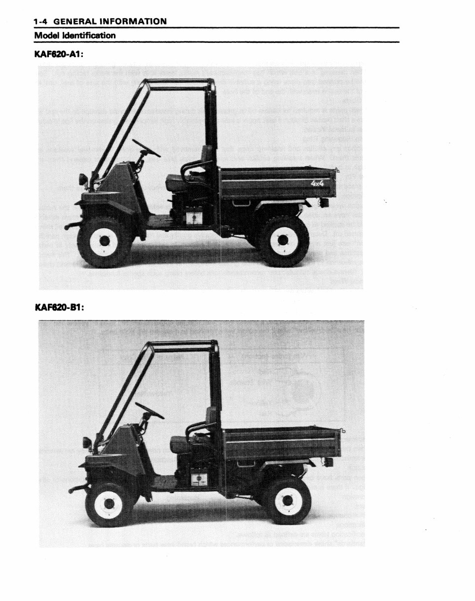
1-4 GENERAL INfORMATION Modell Identification ,KAFI2O-A1 : KAF820-81:
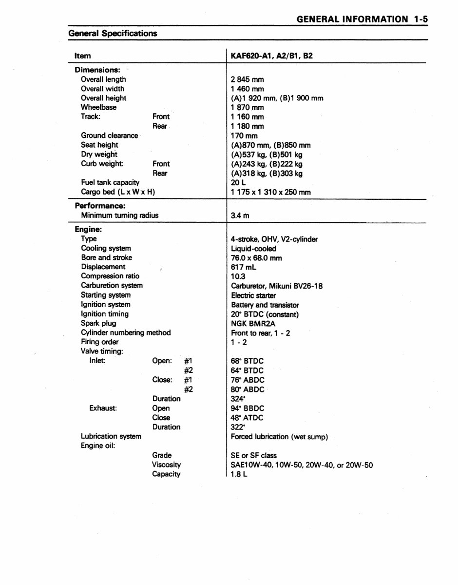
General Specifications Item Dimensions:: Overall length Overall width Overall heiight Wheelbase Track: Ground clearance Seat height iDryweight Front· Rear. Curb weight: Front Rear Fuel tank capacity Cargo bed (L x W x H) Performance: Minimum tuming radius Engine: Type Cooling system Bore and stroke Displacement Compression ratio Carburetion system Starting system Igniti!on .system Ignition timing Spark plug CyHnder numbering method Firing order Valve tilning: Inlet Open: Exhaust: Lubrication system Engin~ oil: Close: Duration Open Close Dura,tion Grade Viscosity Capacity #1 #2- #1 #2 GENER.AL INFORMATION 1-5 KAF620-A1, A2/B1, 82 2845 mm 11460 mm (A)1 920 mm. (B}1 900 mm 1870.mm 1160 mm 1180 mm 170mm (A)870 mm, (B)850 mm (A)537 kg, (B)501 kg (A)243 kg, (B) 222 kg, (A}318 kg, (B)303 kg 20 L 1175x1310x250mm 3.4m 4·stroke, OHV, V2·cvlinder Liquid-cooled 76.0 x 68.0 mm 617mL 10.3 Carburetor, M ikuni BV26-18 Electric starter Battery and transistor 20· BlDC (constant) NG!I< BMR2A Front to rear, 1 - 2 1 - 2 68° BTDC 64" BTDC 76· ABDC B<rABDC 324" 94" BBDC ,48" ATOC :322" Forced lubrica,tion (wet sump) I SE or SF class SAE10W·40, 1 OW-50, 20W-40, or 20W·50 1.8 L
The 1993-2003 Kawasaki Mule 2500/2510/2520 Service & Repair Manual is a comprehensive guide covering all aspects of servicing and repairing Kawasaki Mule utility vehicles made between 1993 and 2003. This manual is essential for anyone who owns or works with these vehicles, whether you're a professional mechanic or a do-it-yourself enthusiast.
The manual provides detailed information on all the systems and components of the Kawasaki Mule 2500, 2510, and 2520 models, including the engine, transmission, suspension, brakes, electrical system, and more. It contains step-by-step instructions for performing routine maintenance tasks, such as oil changes and spark plug replacements, as well as more complex repairs, such as engine overhauls and transmission rebuilds.
The manual is designed to be easy to use, with clear and concise instructions, diagrams, and illustrations. It also includes helpful tips and troubleshooting advice to help you diagnose and fix common problems. The manual covers all models of the Kawasaki Mule 2500, 2510, and 2520 made between 1993 and 2003.
In addition to providing detailed repair and maintenance instructions, the 1993-2003 Kawasaki Mule 2500/2510/2520 Service & Repair Manual also includes information on safety precautions and proper tool usage. With this manual at your fingertips, you'll be able to tackle any repair job on your Kawasaki Mule with confidence and ease.
As a digital PDF file, this manual is easily accessible on your computer, tablet, or smartphone, making it a convenient and portable resource. Whether you're at home or in the shop, you'll have the information you need to keep your Kawasaki Mule running smoothly and reliably.
Recently Viewed
5,521,897Happy Clients
2,594,462eManuals
1,120,453Trusted Sellers
15Years in Business
Price:
Actual Price:
1993-2003 Kawasaki Mule 2500/2510/2520 Service & Repair Manual