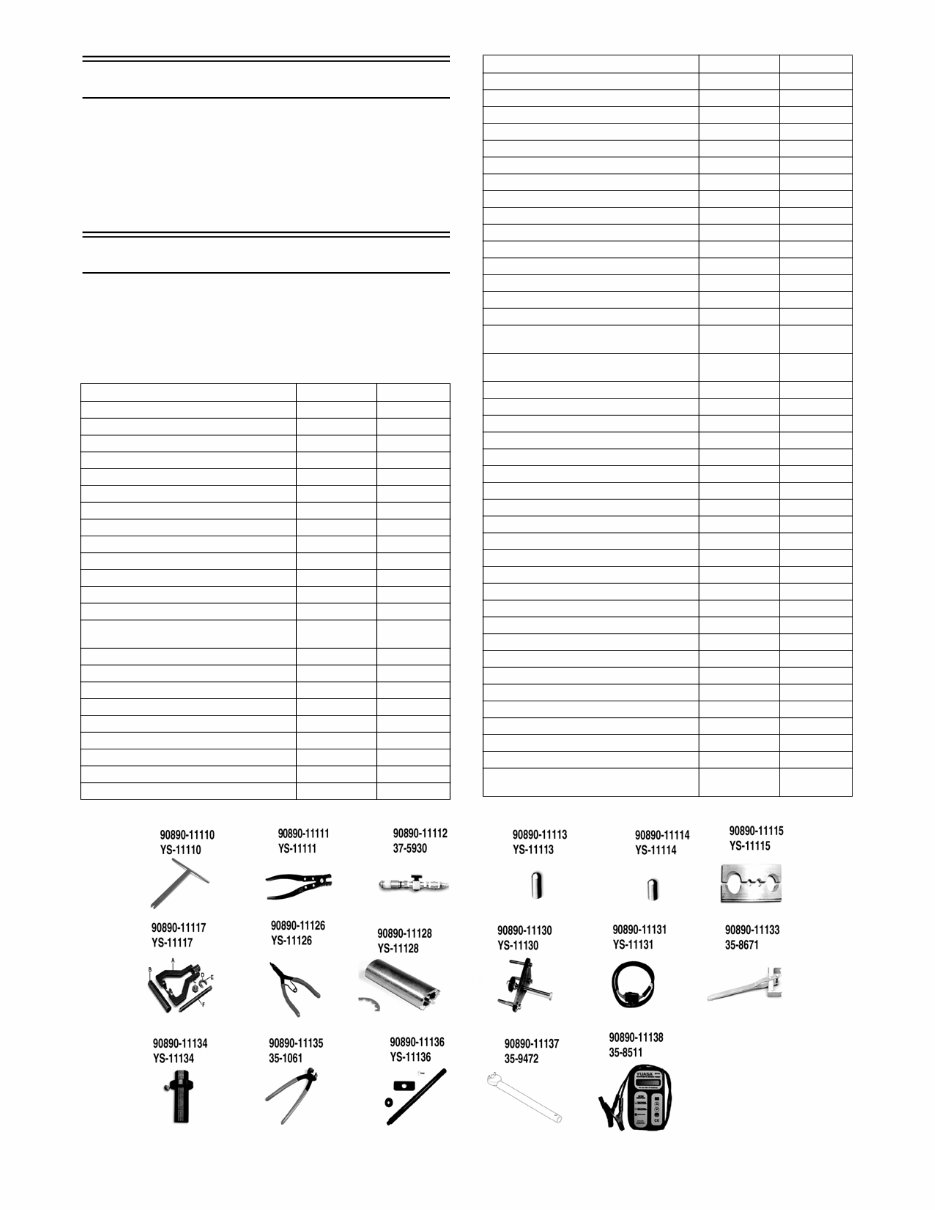
1 General Information NOTE: Whenever a part is worn excessively, cracked, or damaged in any way, replacement is necessary. NOTE: Some illustrations and photographs used in this manual are used for clarity purposes only and are not designed to depict actual conditions. Special Tools A number of special tools must be available to the techni- cian when servicing snowmobile. NOTE: Special tools are available from the Yamaha Ser- vice Parts Department or K&L Tool Supply Company. Snow_tool_2014A Description Yamaha p/n K&L p/n Engine Tachometer 90793-80009 YU-08036-C Rotor Holder 90890-01235 YU-01235 Piston Pin Puller 90890-01304 YU-24460-01 Radiator Pressure Tester 90890-01325 YU-24460-01 Radiator Pressure Tester Adapter 90890-01352 YU-33984 Heavy Duty Puller 90890-01362 YU-33270-B Oil Filter Wrench 90890-01469 YM-01469 YXR Clutch Bushing Jig Kit 90890-01528 YS-39752 Clutch Bushing Press 90890-01529 YS-42424 Primary Clutch Holder 90890-01701 YS-01880-A Clutch Spider Separator 90890-01711 YS-28890-C Track Clip Installation Tool 90890-01721 YS-91045-C Clutch Separator Adapter 90890-01740 YS-34480 Clutch Puller 90890-01898 YS-01881-A YS-1881-1 Engine Compression Tester 90890-03081 YU-33233 Carb Synchronizer 90890-03094 YU-44456 Dial Indicator 90890-03097 YU-A8428 Analog Pocket Tester 90890-03112 YU-03112-C Fuel Pressure Gauge 90890-03153 YU-03153 Fuel Pressure Tester 90890-11143 YS-11143 Carb Angle Driver 2 90890-03173 Model 88 Multimeter 90890-03174 YU-A1927 Fuel Pressure Adapter 90890-03176 YM-03176 Kit, Diagnostics Tool (YSDT) 90890-03233 Valve Spring Compressor 90890-04019 YM-04019 Bearing Driver 40 mm 90890-04058 YM-04058 Crankshaft Protector 90890-04089 YM-33282 Valve Lapping Tool 90890-04101 YM-A8998 VSC Adapter 19.5mm 90890-04114 YM-04114 Valve Guide Remover (4.5mm) 90890-04116 YM-04116 Valve Guide Installer (4.5mm) 90890-04117 YM-04117 Valve Guide Reamer (4.5mm) 90890-04118 YM-04118 Mechanical Seal Installer 90890-04145 Piston Ring Compressor 90890-05158 YM-08037 Opama PET-4000 Spark Checker 90890-06754 YM-34487 Rear Spring Installer 90890-11110 YS-11110 Hose Clamp Installation Tool 90890-11111 YS-11111 Inflation Injector 90890-11112 37-5930 Bearing Cap Seal Protector 1/2 in OD x 3/ 8 in ID 90890-11113 YS-11113 Bearing Cap Seal Protector 5/8 in OD x 3/ 8 in ID 90890-11114 YS-11114 Shock Body / Rod Clamping Tool 90890-11115 YS-11115 Puller, Idler Wheel Kit (Includes * below) 90890-11117 YS-11117 * A Handle 90890-11118 YS-11118 * B Insertion Tool (1.0") 90890-11119 YS-11119 * B Insertion Tool (1.25") 90890-11120 YS-11120 * C Pivot Plate 90890-11121 YS-11121 * D Adapter Plate (1.0") 90890-11122 YS-11122 * D Adapter Plate (1.25") 90890-11123 YS-11123 * E Cap Screw 90890-11124 YS-11124 * F Puller Bolt 90890-11125 YS-11125 Snap Ring Pliers 90890-11126 YS-11126 Socket 90890-11128 YS-11128 Brake Caliper Bearing Puller 90890-11130 YS-11130 Hood Harness Extension 90890-11131 YS-11131 Spring Tool 90890-11133 35-8671 Piston Locator 90890-11134 YS-11134 Fuel Hose Clamp Tool 90890-11135 35-1061 Piston Locator 90890-11136 YS-11136 Spanner Wrench 90890-11137 35-9472 Battery Tester 90890-11138 35-8511 Shift Actuator Test Harness 90890-11141 YS-11141 Fuel Tank Filler Neck Nut Wrench 90890-11142 YS-11142 Yamaha Bond 1215 90890-85505 Angle Gauge Locally Sourced Description Yamaha p/n K&L p/n
2 Snowmobile Identification The Yamaha Snowmobile has two important identifica- tion numbers. The Vehicle Identification Number (VIN) is stamped into the tunnel near the right-side footrest or on top of the tunnel. The decal also displays pertinent production information. The Engine Serial Number (ESN) is stamped into the crankcase of the engine. These numbers are required to complete warranty claims prop- erly. No warranty will be allowed by Yamaha if the engine serial number or VIN is removed or mutilated in any way. Recommended Gasoline and Oil RECOMMENDED GASOLINE The recommended gasoline to use in these snowmobiles is 87 octane unleaded. In many areas, oxygenates are added to the gasoline. Oxygenated gasolines containing up to 10% ethanol are acceptable gasolines. When using ethanol blended gasoline, it is not necessary to add a gasoline antifreeze since ethanol will prevent the accumulation of moisture in the fuel system. RECOMMENDED OIL The recommended oil to use is Semi-Synthetic Yamalube 0W-30 oil. The engine oil should be changed every 4000 km (2500 miles) before prolonged storage and the oil filter should be changed every 20,000 km (12,500 miles). Engine Break-In The engine (when new or rebuilt) requires a short break-in period before the engine is subjected to heavy load conditions. This engine does not require any pre-mixed fuel during the break-in period. There is never a more important period in the life of the engine than the first 500 km (300 miles). Since the engine is brand new, do not put an excessive load on it for the first 500 km (300 miles). The various parts in the engine wear and polish themselves to the correct operat- ing clearances. During this period, prolonged full throttle operation or any condition that might result in engine overheating must be avoided. Operating your snowmobile for the first time: Start the engine and let it idle for 15 minutes. 0-160 km (0–100 miles): Avoid prolonged operation above 6000 RPM. 160-500 km (100–300 miles): Avoid prolonged operation above 8000 RPM. 500 km (300 miles) and beyond: The snowmobile can now be operated normally. NOTE: After 800 km (500 miles) of operation, the engine oil must be changed and the oil filter replaced. If any engine trouble should occur during the engine break-in period, immediately have a Yamaha dealer check the snowmobile. Drive Belt Break-In Drive belts require a break-in period of approximately 40 km (25 miles). Drive the snowmobile for 40 km (25 miles) at 3/4 throttle or less. By revving the engine up and down (but not exceeding 100 km/h [60 mph]), the exposed cord on the side of a new belt will be worn down. This will allow the drive belt to gain its optimum flexibility and will extend drive belt life. NOTE: Before starting the snowmobile in extremely cold temperatures, the drive belt should be removed and warmed up to room temperature. Once the drive belt is at room temperature, install the drive belt. Genuine Parts When replacement of parts is necessary, use only genuine Yamaha parts. They are precision-made to ensure high quality and correct fit. Varying Altitude Operation Operating a snowmobile at varying altitudes requires recal- ibration of drive system components. Following are basic altitude theories for clutching, engine, suspension, and track. CLUTCHING The clutch may require tuning depending upon where the snowmobile will be operated and the desired handling characteristics. The clutch can be tuned by changing the engagement and shifting speeds. Clutch engagement speed is defined as the engine speed at which the snowmobile first begins to move from a complete stop. CAUTION Do not use white gas or gasoline containing methanol. Only Yamaha approved gasoline additives should be used. CAUTION Any oil used in place of the recommended oil may cause serious damage. CAUTION Any oil used in place of the recommended oil could cause serious engine damage. CAUTION Never run the engine with the drive belt removed. Exces- sive revving of the engine could result in serious engine damage and primary sheave failure.
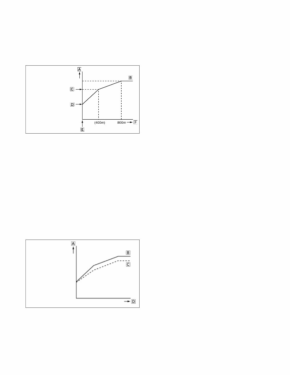
3 Shifting speed is defined as the engine speed reached when the snowmobile has travelled 800 m (2,500 ft) after being started at full-throttle from a dead stop. Normally, when a snowmobile reaches shifting speed, the snowmobile speed increases but the engine speed remains nearly constant. Under unfavorable conditions (wet snow, icy snow, hills, or rough terrain), however, engine speed may decrease after the shifting speed has been reached. CLUTCHA High altitude tuning Atmospheric pressure decreases and engine output becomes low at high altitude locations. Because of this, clutch engagement speed and shifting speed also decrease and unable to maximize the engine output power. To maximize the engine output, tuning for increasing clutch engagement speed and shifting speed is necessary. This setting is called high altitude tuning. The following changes are usually performed in high altitude tuning. • To increase the clutch engagement and shifting speed, changing to a larger spring constant or using lighter weights and rivets. (decreasing primary sheave thrust) • Increasing the reduction ratio of the driven gear/drive gear. (increasing the driving performance) Refer to “HIGH ALTITUDE TUNING”. CLUTCHB ENGINE A normally aspirated engine will generate more horse- power at sea level than it does at higher altitudes. The reason is that the higher you go, less oxygen is available for the engine to use during its combustion process. Less oxygen means it needs less fuel to obtain the correct air/ fuel ratio to operate properly. This is why the fuel ratio has to be recalibrated. High alti- tude engines operate as though they have a lower com- pression ratio. This, along with less oxygen and less fuel, means that the engine generates less horsepower. All of these characteristics will become more evident the higher the altitude. SUSPENSION Trail riding versus powder snow riding versus combina- tion riding will all require different suspension settings. The normal setting for front ski suspension is as little spring pre-load tension as possible for powder snow riding allow- ing the skis to float across the snow with the least amount of resistance. Trail riding will require more spring tension to carry the varying load more effectively. Many different settings and spring tensions to consider exist when adjust- ing for riding style and snow conditions. The rear suspension has a number of spring settings that produce different riding characteristics (see Suspension - Suspension Setup Basics). The front arm spring and shock will also affect the ride and handling when either on a trail or in powder snow. A strong spring setting on this shock will cause the snowmobile to tend to “dig” more when riding in the powder snow rather than climbing up on top of the snow. But, it will work more effectively when riding on a trail. A softer spring setting will allow the front of the rear suspension to collapse much quicker and change the angle of the track to the snow. A more gradual angle will tend to raise the snowmobile up on the snow rather than digging into it. Many possible variables and adjustments to the rear sus- pension exist depending on snow conditions, riding style, and type of terrain. These adjustments can be made to indi- vidualize the snowmobile to the riding style of the operator. Finally, track tension should be looked at to make sure that it is within recommended specifications to affect the efficiency of the snowmobile. On models with the torque sensing link, the track is actually tightening as the suspension moves through its range of motion causing the track to sag in the middle and rub on the top part of the rear suspension arm. TRACK Carefully matching the riding requirements to the type of track will ensure the maximum use of all available engine power. Lug height and track durometer are the two main concerns when selecting a track for various riding styles. Tracks exist with lug heights from 31.75 - 66.04 mm (1.25 - 2.6 in.) to accommodate various snow conditions. Generally, the deeper the snow, the taller the lug. It must be noted that the installation of any deep-lug track may reduce top end speed and promote premature wear strip wear in marginal snow conditions. Durometer is a measurement of how hard a rubber is. The lugs on most tracks range between 60 and 80 durometer. On the durometer scale, the higher the number, the harder the lugs. For riding in deep powder snow, a softer durom- eter track works best. The softer rubber allows the track to “give” a little and pack the snow creating lift rather than digging its way straight down. When hill-climbing, the harder lug of an 80 durometer track works the best due to penetrating the hard snow creating more bite. A. Engine speed B. Good condition C. Shifting speed D. Clutch engagement speed E. Starting position F. Distance travelled A. Engine speed B. Speed at maximum output C. Low speed D. Distance travelled
4 Some tracks come with a dual durometer rating, such as a track with a 80/60 durometer rating. The lugs on this track are 80% 80 durometer rubber, and the top 20% is made of the softer 60 durometer rubber. This track is designed to be a good all-around track for riding mostly in deep powder snow but can climb the occasional hard snow hill. Preparation For Storage Prior to storing the snowmobile, it must be properly ser- viced to prevent corrosion and component deterioration. 1. Clean the seat cushion with a damp cloth and a Vinyl Protectant. 2. Clean the snowmobile thoroughly by hosing dirt, oil, grass, and other foreign matter from the skid frame, tunnel, hood, and belly pan. Allow the snowmobile to dry thoroughly. DO NOT get water into any part of the engine. 3. Change the engine oil. 4. Plug the exhaust system outlet with a clean cloth. 5. Fill the gas tank to its rated capacity; then add Yamaha Fuel Stabilizer to the gas tank following directions on the container for the stabilizer/gasoline ratio. Tighten the gas tank cap securely. 6. With the snowmobile level, check the lubricant level in the chain case. If low, add chain lube through the fill plug hole. 7. Remove the drive belt from the primary sheave/sec- ondary sheave. Lay the belt on a flat surface or slide it into a cardboard sleeve to prevent warping or dis- tortion during storage. 8. Clean and inspect the primary sheave and secondary sheave. 9. Apply light oil to the upper steering post bushing and shafts of the shock absorbers. 10. Lubricate the rear suspension with all-temperature grease. 11. Tighten all nuts, bolts, and cap screws making sure all nuts, bolts, and cap screws are tightened securely. Make sure all rivets holding the components together are tight. Replace all loose rivets. 12. Clean and polish the hood, console, and chassis. DO NOT USE SOLVENTS. THE PROPELLANT WILL DAMAGE THE FINISH. NOTE: Disconnect the battery cables making sure to disconnect the negative cable first; then clean the battery posts and cables. Charge the battery. 13. If possible, store the snowmobile indoors. Raise the track off the floor by blocking up the back end mak- ing sure the snowmobile is secure. Loosen the track adjusting bolts to reduce track tension. Cover the snowmobile with a machine cover or a heavy tarpau- lin to protect it from dirt and dust. 14. If the snowmobile must be stored outdoors, position the snowmobile out of direct sunlight; then block the entire snowmobile off the ground making sure the snowmobile is secure. Loosen the track adjusting bolts to reduce track tension. Cover with a machine cover or a heavy tarpaulin to protect it from dirt, dust, and rain. Preparation After Storage Taking the snowmobile out of storage and correctly pre- paring it for another season will assure many miles and hours of trouble-free snowmobiling. Yamaha recom- mends the following procedure: 1. Clean the snowmobile thoroughly. Polish the exterior of the snowmobile. 2. Clean the engine. Remove the cloth from the exhaust system. Check exhaust system and air-intake silencer for obstructions. 3. Inspect all control wires and cables for signs of wear or fraying. Replace if necessary. Use cable ties or tape to route wires and cables away from hot or rotat- ing parts. 4. Inspect the drive belt for cracks and tears. Check belt specifications. Replace if damaged or worn. Install the drive belt. NOTE: If the old belt is worn but in reasonable con- dition, retain it with the snowmobile as a spare in case of an emergency. 5. Tighten all nuts, bolts, and cap screws making sure all -nuts, bolts, and cap screws are tightened securely. 6. If not done during preparation for storage, lubricate the rear suspension with all-temperature grease. 7. Check the coolant level and all coolant hoses and connections for deterioration or cracks. Add properly mixed coolant as necessary. 8. Charge the battery until fully charged; then connect the battery cables making sure to connect the posi- tive cable first. Test the electric start system. 9. Inspect the entire brake system, all controls, head- light, taillight, brakelight, ski wear bars, and head- light aim; adjust or replace as necessary. 10. Adjust the track to the proper tension and alignment. After Break-In Checkup/ Checklist Certain areas require adjustment after the break-in period in order to obtain peak performance and include the following. CAUTION Sealed batteries require charging if left for extended non- start periods. Yamaha recommends trickle charging once a month. Follow the manufacturer’s instructions and cautions. CAUTION Avoid storing in direct sunlight and using a plastic cover as moisture may collect on the snowmobile causing corrosion.
5 DRIVE BELT POSITION — Drive belt length, condi- tion, and position are all important for peak performance. After the break-in period, drive belt deflection should be checked according to the instructions given in the Drive Train/Track/Brake Systems section of this manual. PRIMARY SHEAVE/SECONDARY SHEAVE OFF- SET — If premature drive belt wear is experienced or if the drive belt turns over, offset must be checked. Also, offset must be checked whenever either the primary sheave or secondary sheave is serviced. TRACK TENSION AND ALIGNMENT — A certain amount of stretch occurs on all tracks during the first 800 km (500 miles). The track must be inspected/adjusted after the first 80 to 160 km (50 to 100 miles) to the speci- fications given in the Track Specifications sub-section of this section and periodically thereafter. If these adjust- ments aren’t performed, the track may “derail” which leads to track and slide rail damage. Along with these major areas, other areas should be checked and adjusted. Below is a list of items to check after the break-in period. The recommended mileage for this inspection is between 160 and 480 km (100 and 300 miles). Check drive belt position - primary sheave/secondary sheave offset Adjust track tension and alignment Check throttle cable tension Check engine idle Check coolant level Check chain case lubricant level Check engine oil level Check lights (high/low beam, brakelight) Check safety switch operation Check engine compartment for any rubbing components Check steering hardware for tightness Check skid frame and A-arm mounting hardware for tight- ness Check brake lever travel and adjustment Grease all lubrication points Engine Specifications Electrical Specifications * Harness plugged in The main harness connectors must be unplugged (except on primary coil and regulator/rectifier tests) and tested by pressing the starter button. NOTE: Lighting coil output is unregulated voltage. ITEM Engine Model Number 8JK Displacement 1049 cc Compression Ratio 11:1 Bore x Stroke 82.04 x 66.29 mm (3.23 × 2.61”) Cooling System Liquid Spark Plug (NGK) CR9E Spark Plug Gap 0.71-0.79 mm (0.028-0.031”) Piston Skirt/Cylinder Clearance 0.036-0.061 mm (0.0014-0.0024”) Piston Pin Diameter 18.991-19.000 mm (0.7477-0.7480”) Piston Pin Bore Diameter 19.004-19.015 mm (0.7482-0.7486”) Piston Pin to Piston Pin Bore Clearance0.004-0.024 mm (0.0002-0.0009”) Connecting Rod: Small End Diameter 19.005-19.027 mm (0.7482-0.7491”) Crankshaft Pin/Connecting Rod Big End Clearance 0.033-0.050 mm (0.0013-0.0020”) Connecting rod: Big End Diameter 41.000-41.018 mm (1.6142-1.6149”) Piston Ring End Gap (Top) (2nd) (Oil) 0.33-0.46 mm (0.013-0.018”) 0.71-0.84 mm (0.028-0.033”) 0.20-0.61 mm (0.008-0.024”) Piston Ring/ (1st - Top) Groove Clearance (2nd) (Oil) 0.030-0.070 mm (0.0012-0.0028”) 0.020-0.060 mm (0.0008-0.0024”) 0.040-0.110 mm (0.0016-0.0043”) Piston Diameter (11 mm from bottom edge) 81.95-81.97 mm (3.2264-3.2270”) Cam Lobe Height (Intake) 34.25 mm (1.3484”) Cam Lobe Height (Exhaust) 33.85 mm (1.3327”) Cam Lobe Width (Intake/Exhaust) 24.85 mm (0.9783”) Camshaft Journal Diameter 24.46-24.47 mm (0.9630-0.9635”) Camshaft Journal Clearance 0.03-0.06 mm (0.0011-0.0024”) Crank Pin Diameter 37.976-38.000 mm (1.4951-1.4961”) Crankshaft Runout (max) 0.3 mm (0.012”) Crankshaft Main Bearing Clearance 0.03-0.05 mm (0.0011-0.0018”) Crankshaft/Rod Bearing Clearance 0.03-0.05 mm (0.0013-0.0020”) Valve Guide Inside Diameter (Intake) 4.475-4.490 mm (0.1762-0.1768”) Valve Guide Inside Diameter (Exhaust) 4.500-4.512 mm (0.1772-0.1776”) Valve Guide/Stem Clearance (Intake) 0.01-0.04 mm (0.0004-0.0015”) Valve Guide/Stem Clearance (Exhaust) 0.03-0.05 mm (0.0010-0.0020”) Valve Face Width (Intake) 0.08-1.20 mm (0.0315-0.0472”) Valve Face Width (Exhaust) 0.50-0.90 mm (0.0197-0.0354”) Component Test Value + Test Connections - (Normally Closed Ignition) Magneto Coil (3 tests) 0.15-0.23 ohm white white Primary Ignition Coil 1.19-1.61 ohms red/green gray/green Secondary Ignition Coil 8.5k-11.5k ohms red/green gray/green Crankshaft Position Sensor 336-504 ohms blue/white green/white Voltage Regulator/Rectifier* 12-14.5 DC Volts terminal terminal Magneto Coil (no load) 36-44 AC Volts white white Oil Level Sensor Less than 1 ohm (float end down) terminal terminal Ignition Switch Less than 1 ohm (key in OFF position) terminal terminal ! WARNING Most voltages generated by the ignition system are suf- ficient to interrupt pacemakers! All technicians, espe- cially those using pacemakers, must avoid contact with all electrical connections when pressing the starter but- ton or after the engine has been started.
6 Drive System Specifications Model Elevation Primary Clutch Spring Clutch Weight Clutch Rivets Roller Diameter (mm) Secondary Clutch Spring Drive Belt Shift RPM Engagement RPM Top Gear Bottom Gear Chain Links Outer Center Inner 1.25" Track SR10RD SR10RS, RL SR10LD, LS ~800m (~2500 ft) Blue Silver Blue 35Kgf 2.0Kgf/mm 8GL00 D C C 15.6 PINK 1211kgfmm/ rad Preload 70 8JP-00 Approx. 8750 Approx. 3800 24 50 92 600~1400m (2000~4500 ft) F D D Approx. 3800 24 50 92 1200~2000m (4000~6500 ft) G D D Approx. 3800 22 48 90 1800~2600m (6000~8500 ft) None D F Approx. 3900 21 49 90 2400~3000m (8000~10000 ft) None D None Approx. 3900 21 49 90 1.7"/1.75" Track SR10RS, RL SR10LS, LL ~800m (~2500 ft) Blue Silver Blue 35Kgf 2.0Kgf/mm 8GL00 D C C 15.6 PINK 1211kgfmm/ rad Preload 70 8JP-00 Approx. 8750 Approx. 3800 21 49 90 600~1400m (2000~4500 ft) F D D Approx. 3800 21 49 90 1200~2000m (4000~6500 ft) G D D Approx. 3800 21 49 90 1800~2600m (6000~8500 ft) None D F Approx. 3900 21 49 90 2400~3000m (8000~10000 ft) None D None Approx. 3900 21 49 90 SR10SD SR10XS, XL ~800m (~2500 ft) Blue Silver Blue 35Kgf 2.0Kgf/mm 8GL00 D C C 15.6 PINK 1211kgfmm/ rad Preload 70 8JP-00 Approx. 8750 Approx. 3800 21 41 86 600~1400m (2000~4500 ft) F D D Approx. 3800 21 41 86 1200~2000m (4000~6500 ft) G D D Approx. 3800 24 50 92 1800~2600m (6000~8500 ft) None D F Approx. 3900 21 49 90 2400~3000m (8000~10000 ft) None D None Approx. 3900 21 49 90 MTX NA SR10M53 SR10M53S SR10M62S SR10M62L ~800m (~2500 ft) Green Green Green 40Kgf 2.75Kgf/ mm 8BU10 A N/A A 14.5 PINK 1211kgfmm/ rad Preload 30 8JP-00 Approx. 8750 Approx. 3700 21 49 90 600~1400m (2000~4500 ft) F N/A C Approx. 3750 21 49 90 1200~2000m (4000~6500 ft) G N/A D PINK 1211kgfmm/ rad Preload 40 Approx. 3800 21 49 90 1800~2600m (6000~8500 ft) G N/A G Approx. 3850 21 49 90 2400~3000m (8000~10000 ft) None N/A None Approx. 3900 21 49 90 MTX EUROPE SR10M53S SR10M62S SR10M62L ~800m (~2500 ft) Blue White Blue 45Kgf 2.0Kgf/mm 8FN00 B N/A B 16.5 PINK 1211kgfmm/ rad Preload 50 8JP-00 Approx. 8750 Approx. 3000 24 50 92 600~1400m (2000~4500 ft) E N/A D Approx. 3000 24 50 92 1200~2000m (4000~6500 ft) H N/A D Approx. 3100 22 48 90
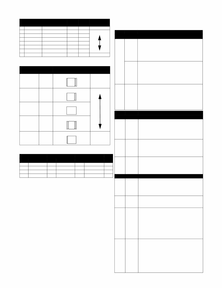
7 WEIGHT RIVETS CLUTCH ROLLERS CHAIN CASE COMPONENTS DRIVE SYSTEM INFLUENCE Components of the V-belt transmission having a direct impact on the shifting function are described below. Part Number Material Length Weight Effect A 90261-06033 Steel 17.2 mm 4.5g Increase Force B 90269-06006 Steel with hole 17.2 mm 3.6g C 90261-06034 Steel 13.9 mm 3.6g D 90261-06019 Steel 13.3 mm 3.1g E 90266-06002 Steel with hole 13.3 mm 2.44g F 90261-06015 Steel 10.3 mm 2.44g G 90261-06028 Aluminum 10.3 mm 0.85g H 90266-06001 Aluminum with hole 13.3 mm 0.85g Decrease Force Part Number Outside Diameter Identification Mark (Width) Effect 8FG-17624-00 14.5 mm Groove and Machined Increase Force 8FG-17624-10 15.0 mm Groove 8FG-17624-20 15.6 mm No Mark 8FG-17624-30 16.0 mm Groove and Groove 8FG-17624-40 16.5 mm Machined Decrease Force TOP GEAR BOTTOM GEAR CHAIN Ratio Teeth P/N Teeth P/N Links P/N 21 8JP-E769A-10 41 8JP-G7587-10 86 8JP-RAM01-20 1.952 24 8JP-E769A-40 50 8JP-G7587-00 92 8JP-RAM01-00 2.083 22 8JP-E769A-20 48 8JP-G7587-80 90 8JP-RAM01-10 2.182 21 8JP-E769A-10 49 8JP-G7587-90 90 8JP-RAM01-10 2.333 Part Element Impact on the shifting function Primary sheave Spring Preload • A larger preload increases the clutch engagement speed, and the shifting speed tends to rise accord- ingly. Shifting tends to become somewhat harder. (increasing the spring reaction force) • A smaller preload decreases the clutch engagement speed, and the shifting speed tends to drop accord- ingly. Shifting tends to become somewhat easier. (decreasing the spring reaction force) Spring rate • A larger spring rate increases the shifting speed. It also slightly increases the clutch engagement speed. Shifting tends to become somewhat harder. (increas- ing the spring reaction force) • A smaller spring rate decreases the shifting speed. It also slightly decreases the clutch engagement speed. Shifting tends to become somewhat easier. (decreas- ing the spring reaction force) Weight Shape, weight Shape and weight determine, the size of moment about the center of the weight rotation when the sheave is running. • Heavier weight decreases the clutch engagement and shifting speed. Shifting tends to become some- what easier. (increasing the sheave thrust) • Lighter weight increases the clutch engagement and shifting speed. Shifting tends to become somewhat harder. (decreasing the sheave thrust) Part Element Impact on the shifting function Primary sheave Weight rivet Quantity Material (iron, alu- minum) Rivets are fastened through the hole in the weight. • Using more rivets decreases the clutch engagement and shifting speed. Shifting tends to become some- what easier. (increasing the sheave thrust) • Using less rivets increases the clutch engagement and shifting speed. Shifting tends to become some- what harder. (decreasing the sheave thrust) Roller Outside diameter The outside diameter affects the contact angle with the weight. • A smaller diameter decreases the clutch engage- ment speed. (increasing the sheave thrust) • A larger diameter increases the clutch engagement speed. (decreasing the sheave thrust) Shim Quantity • Using more shims increases the preload and clutch engagement speed. (increasing the spring reaction force) • Using less shim decreases the preload and clutch engagement speed. (decreasing the spring reaction force) Secondary sheave Spring Preload Spring rate (com- pression, torsion) • A larger preload, spring rate or twist angle increases the shifting speed and makes shifting somewhat harder. (increasing the sheave thrust) • A smaller preload, spring rate or twist angle decreases the shifting speed and makes shifting somewhat easier. (decreasing the sheave thrust) Fixed sheave Spring seat Spring fit- ting hole One of the holes may be used selectively to change the spring twist angle (preload). Refer to “ Spring”. Torque cam Cam angle The cam angle determines the degree of sensitivity (spring seat) of load torque detection. • A smaller cam angle increases sensitivity, which in turn increases the sheave thrust to make back shifting easier. The shifting speed tends to increase and shift- ing becomes somewhat harder. (increasing the sheave thrust) • A larger cam angle makes back shifting harder. The shifting speed tends to decrease and shifting becomes somewhat easier. (decreasing the sheave thrust) Shim Quantity Size of the secondary sheave clearance (between fixed sheave and sliding sheave) can be adjusted by the number of shims used. Adjust the clearance when the V-belt wear deterio- rates and belt width becomes smaller. • Using more shims makes secondary sheave clear- ance smaller. • Using less shim makes secondary sheave clearance larger. When the V-belt width is smaller, wrap-around diame- ter of the V-belt on the primary sheave is larger and clutch engagement speed is slightly increased.
This manual covers all versions of the following machines:
2015 Yamaha SR Viper LTX DX 4-Stroke Snowmobiles
2015 Yamaha SR Viper LTX LE 1.25 4-Stroke Snowmobiles
2015 Yamaha SR Viper LTX SE 4-Stroke Snowmobiles
2015 Yamaha SR Viper MTX LE 153 4-Stroke Snowmobiles
2015 Yamaha SR Viper MTX SE 153 4-Stroke Snowmobiles
2015 Yamaha SR Viper MTX SE 162 4-Stroke Snowmobiles
2015 Yamaha SR Viper RTX DX 4-Stroke Snowmobiles
2015 Yamaha SR Viper RTX SE 4-Stroke Snowmobiles
2015 Yamaha SR Viper STX DX 139 4-Stroke Snowmobiles
2015 Yamaha SR Viper XTX LE 4-Stroke Snowmobiles
After payment, our informative repair manual, owners manuals, and parts catalogs contain all the information you'll need to perform repairs, look up parts, or do routine maintenance on your machine. You will have access to information regarding the following topics:
General Information
Routine Maintenance
Engine Removal and Installation
Fuel System
Lubrication and Cooling System
Engine Specifications
Transmission, Drive Chain & Sprockets
Steering System
Shocks
Body Work
Intake & Exhaust
Electrical System
Advanced Troubleshooting
With our repair manuals, find the page pertaining to your job, print it off, and get working on your machine. No more ruining your expensive paper shop manual with grease and dirt.
Broke down on the trail or site and have a smartphone? What a cool way to find your problem and repair it on the trail, no downtime on the job site. With our repair manuals, you instantly have access to the material needed to get you running again. Kind of tough to do that with a paper manual.
And did we mention the fact that you're saving the trees? All our repair manuals come with a lifetime protection policy. If lost or damaged, simply contact us and we'll replace it free of charge for life.
We provide various repair service manuals, workshop manuals, repair manuals, owners manuals, parts catalogs, and other various manuals, all in an electronic format.
UTVs, motorcycles, ATVs, quads, snowmobiles, Seadoo, equipment, small engines, inboards, outboards, and more.
* Instant download
* No shipping cost with download
* Get a download so no waiting, repair it now
Instant download after payment. Thank you.
Recently Viewed
5,521,897Happy Clients
2,594,462eManuals
1,120,453Trusted Sellers
15Years in Business
Price:
Actual Price:
2015 Yamaha SR Viper 4-Stroke Snowmobile Repair Manual