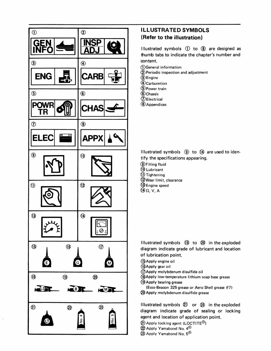
CD ® 1~1f=~1- Ilr8rl~1 @ @ IENGI&I ICARBI~1 @ ® IP<f«R141 ICHASI~ I (j) ® IELECI iii I IAPPXI·'1 @ ~ @ ~ @ ~ @ ~ @ [0] @ [ml @ i @ i @ i - a - m e @ @ ® ~ ~~ ® @m @~ 6 ILLUSTRATED SYMBOLS (Refer to the illustration) Illustrated symbols CD to ® are designed as thumb tabs to indicate the chapter's number and oontent. CDGeneral information ® Periodic inspection and adjustment @Engine @Carburetion @Powertrain ®Chassis (j) Electrical ® Appendices Illustrated symbols @ to @ are used to iden- tify the specifications appearing. @Filling fluid @Lubricant @Tightening @Wear limit, clearance @Engine speed @n,V,A Illustrated symbols @ to ® in the exploded diagram indicate grade of lubricant and location of lubrication point. @Apply engine oil @Apply gear oil @Apply molybdenum disulfide oil @Apply low-temperature lithium soap base grease @Apply bearing grease (Esso-Beacon 325 grease or Aero Shell grease #7) ®Apply molybdenum disulfide grease Illustrated symbols ® or @ in the exploded di~gram indicate grade of sealing or locking agent and location of application point. ® Apply locking agent (LOCTITE®) @Apply Yamabond No. 4® @Apply Yamabond No. 5®
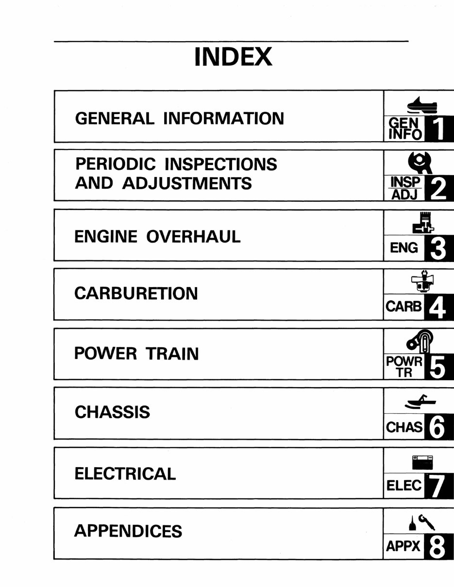
INDEX GENERAL INFORMATION PERIODIC INSPECTIONS AND ADJUSTMENTS ENGINE OVERHAUL CARBURETION POWER TRAIN CHASSIS ELECTRICAL APPENDICES Iii ELEC " APPX
CHAPTER 1. GENERAL INFORMATION MACHINE IDENTIFICATION .. ................ . , ................. 1-1 FRAME SERIAL NUMBER .... . .. ... .. ........ ........ . ..... .. 1-1 ENGINE SERIAL NUMBER .... ............ .... ............... . 1-1 D STORAGE .... . ..... . .............. . ........ . .. . .............. 1-2 PRE-SEASON PREPARATION ..... .. ....... .. ......... . .......... 1-2 IMPORTANT INFORMATION .. ....... .... .. ...................... 1-3 NO FLAME SOURCES ........... ... . .. . .............. .. ...... 1-3 WASHING AND CLEANING ................................... 1-3 RIGHT TOOLS .............. ... .. . .......................... 1-3 MAKING IT NEAT ....... .. .. , ............................... 1-3 TIGHTENING TORQUE ............... . .. , ............... .. .. 1-3 ALL REPLACEMENT PARTS .. ... ............................. 1-4 GASKETS, 01 L SEALS, AND O-RINGS . .. . ....... . .............. 1-4 LOCK WASHERS/PLATES AND COTTER PINS ...... . .. . .... . ..... 1-4 BEARINGS AND OIL SEALS .... .... ........... " . . ........... 1-4 CI RCLIPS .................................................. 1-5 NOTES ON DISASSEMBLY AND ASSEMBLY ..................... 1-5 SPECIAL TOOLS ............................................... 1-6 FOR TUNE UP ..... . ............ . ....... .. .... . ....... ... ... 1-6 FOR ENGI NE SERVICE .... ..... ..... .... . ................... 1-6 FOR POWER TRAIN SERViCE ........................ . ........ 1-7 FOR ELECTRICAL SERVICE .... ... ... . ....................... 1-8 FEATURE . .................................... . .. . ........... 1-9 GEAR TRAIN SYSTEM . ..................... . ................ 1-9
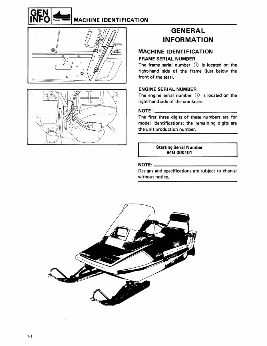
,-, MACHINE IDENTIFICATION CD I " (----.-,2 u .. GENERAL INFORMATION MACHINE IDENTIFICATION FRAME SERIAL NUMBER The frame serial number CD is located on the right-hand side of the frame (just below the front of the seat). ENGINE SERIAL NUMBER The engine serial number CD is located on the right-hand side of the crankcase. NOTE: ____________ _ The first three digits of these numbers are for model identifications; the remaining digits are the unit production number. Starting Serial Number 84G-000101 NOTE: __________________ _ Designs and specifications are subject to change without notice.
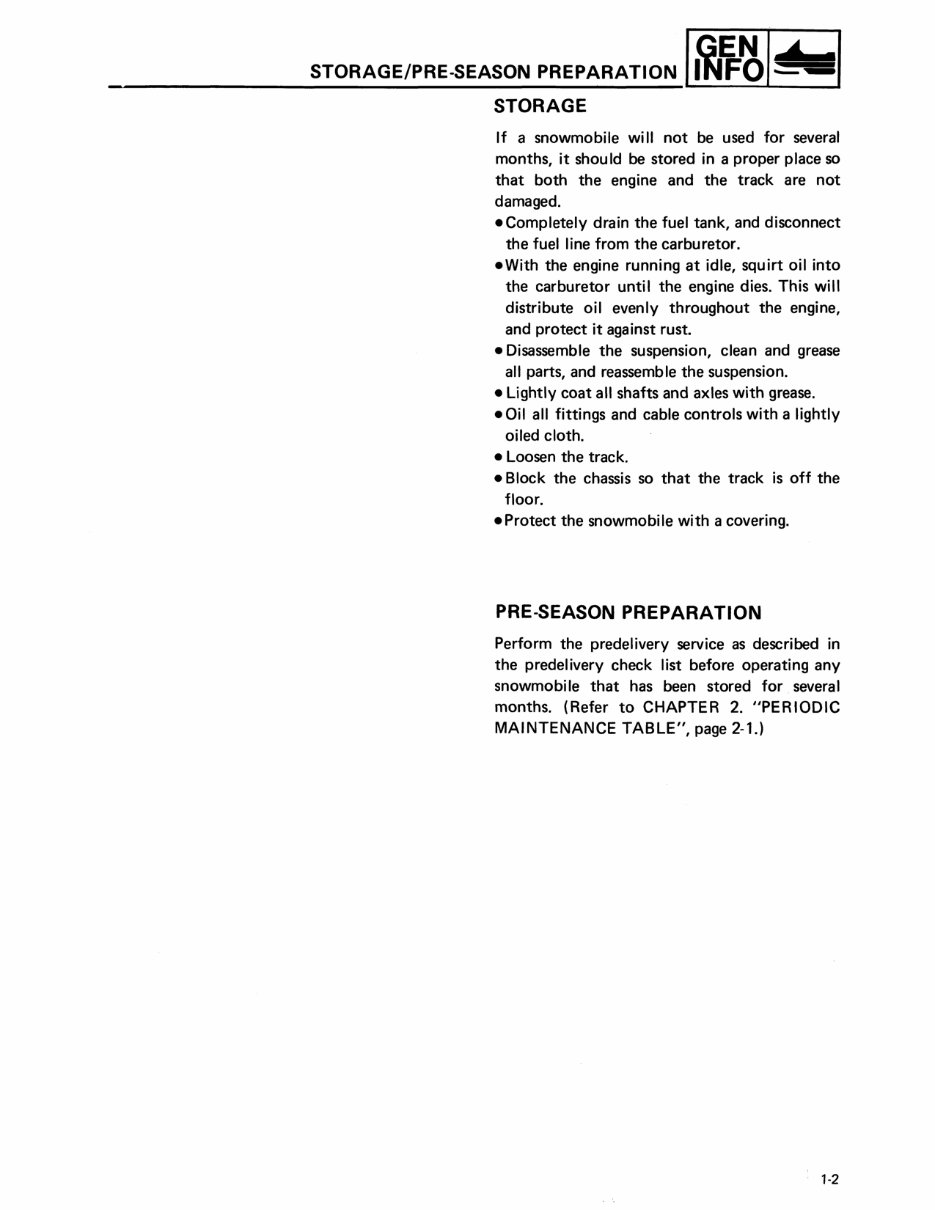
STORAGE/PRE-SEASON PREPARATION IM~~I- STORAGE If a snowmobile wi II not be used for several months, it should be stored in a proper place so that both the engine and the track are not damaged. • Completely drain the fuel tank, and disconnect the fuel line from the carburetor . • With the engine running at idle, squirt oil into the carburetor until the engine dies. This will distribute oil evenly throughout the engine, and protect it aga inst rust. • Disassemble the suspension, clean and grease all parts, and reassemble the suspension. • Lightly coat all shafts and axles with grease. • Oil all fittings and cable controls with a lightly oiled cloth. • Loosen the track. • Block the chassis so that the track is off the floor . • Protect the snowmobile with a covering. PRE-SEASON PREPARATION Perform the predelivery service as described in the predelivery check list before operating any snowmobile that has been stored for several months. (Refer to CHAPTER 2. "PERIODIC MAINTENANCE TABLE", page 2-1.) '·2
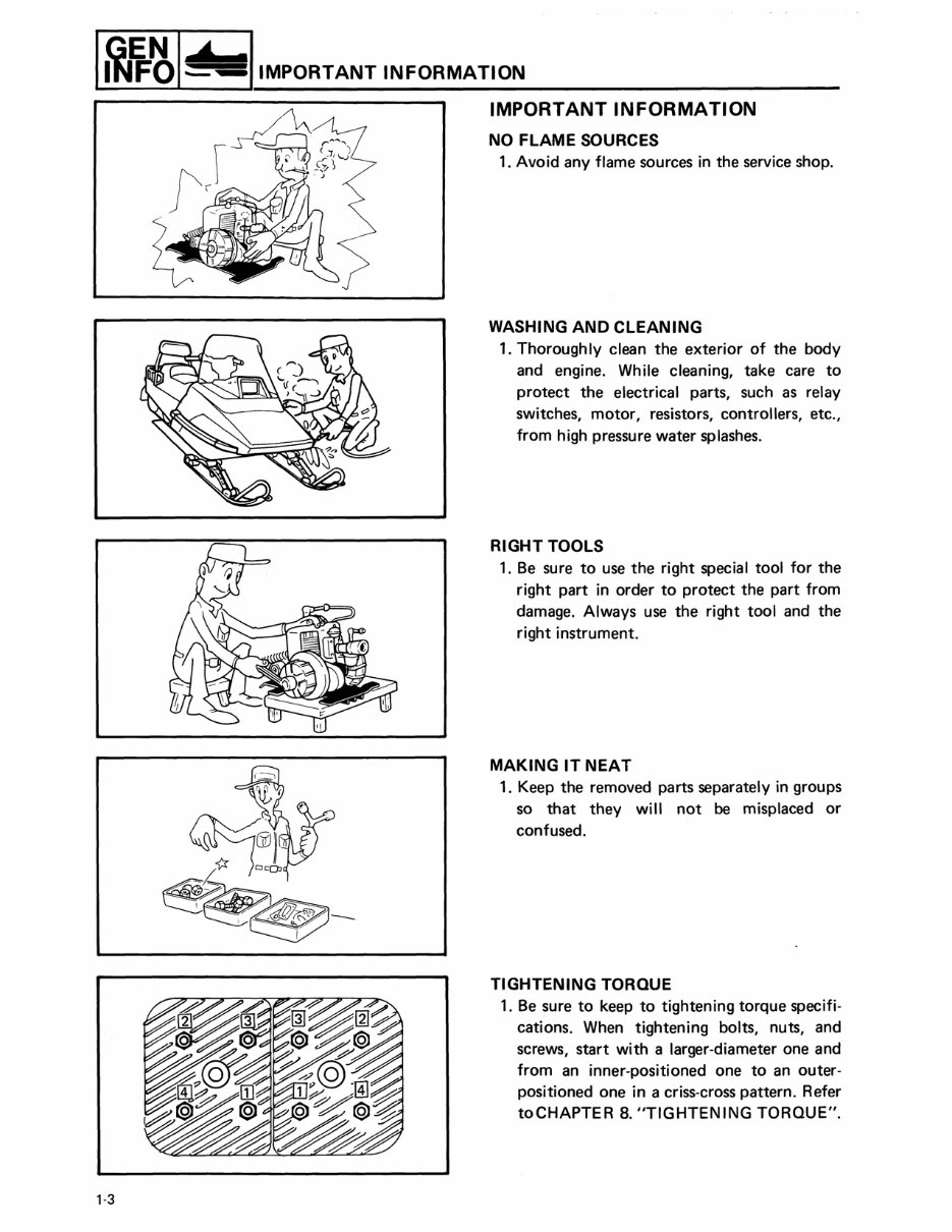
1-3 I IMPORTANT INFORMATION IMPORTANT INFORMATION NO FLAME SOURCES 1. Avoid any flame sources in the service shop. WASHING AND CLEANING 1. Thoroughly clean the exterior of the body and engine. While cleaning, take care to protect the electrical parts, such as relay switches, motor, resistors, controllers, etc., from high pressure water splashes. RIGHT TOOLS 1. Be sure to use the right special tool for the right part in order to protect the part from damage. Always use the right tool and the right instrument. MAKING IT NEAT 1. Keep the removed parts separately in groups so that they will not be misplaced or confused. TIGHTENING TORQUE 1. Be sure to keep to tightening torque specifi- cations. When tightening bolts, nuts, and screws, start with a larger-diameter one and from an inner-positioned one to an outer- positioned one in a criss-cross pattern. Refer toCHAPTER 8. "TIGHTENING TORQUE".
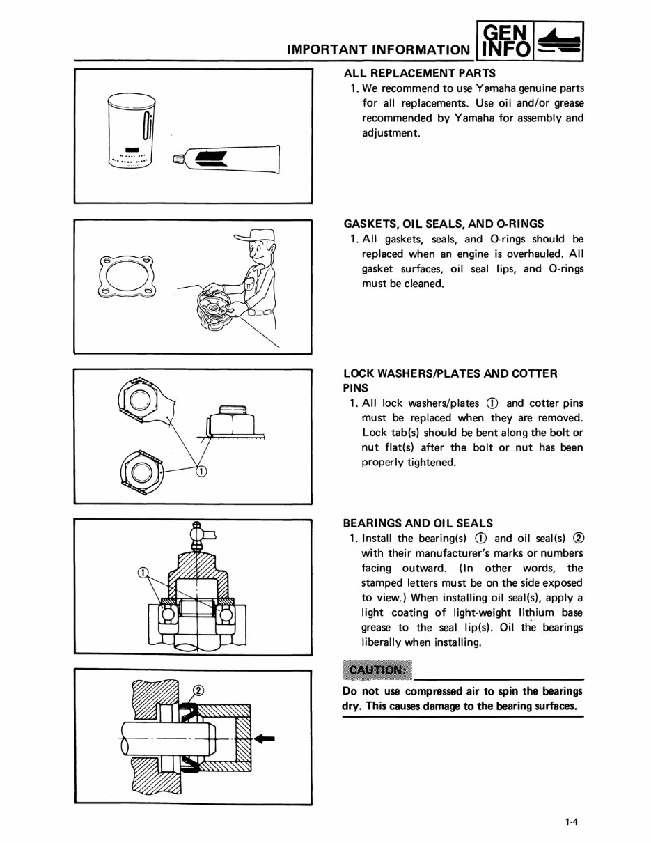
] - ......... ' ~ .... ~~.~ ... / IMPORTANT INFORMATION I~~~I- ALL REPLACEMENT PARTS 1. We recommend to use Yamaha genu ine parts for all replacements. Use oil and/or grease recommended by Yamaha for assembly and adjustment. GASKETS, OIL SEALS, AND 0-RINGS 1. All gaskets, seals, and O-rings should be replaced when an engine is overhauled. A" gasket surfaces, oil seal lips, and O-rings must be cleaned. LOCK WASHERS/PLATES AND COTTER PINS 1. A" lock washers/plates CD and cotter pins must be replaced when they are removed. Lock tab(s) should be bent along the bolt or nut flat(s) after the bolt or nut has been properly tightened. BEARINGS AND OIL SEALS 1. Install the bearing(s) CD and oil seal(s) @ with their manufacturer's marks or numbers facing outward. (In other words, the stamped letters mu st be on the side exposed to view.) When installing oil seal(s), apply a light coating of light-weight lithium base grease to the seal lip(s). Oil th·e bearings liberally when installing. Do not use compressed air to spin the bearings dry. This causes damage to the bearing surfaces. '-4
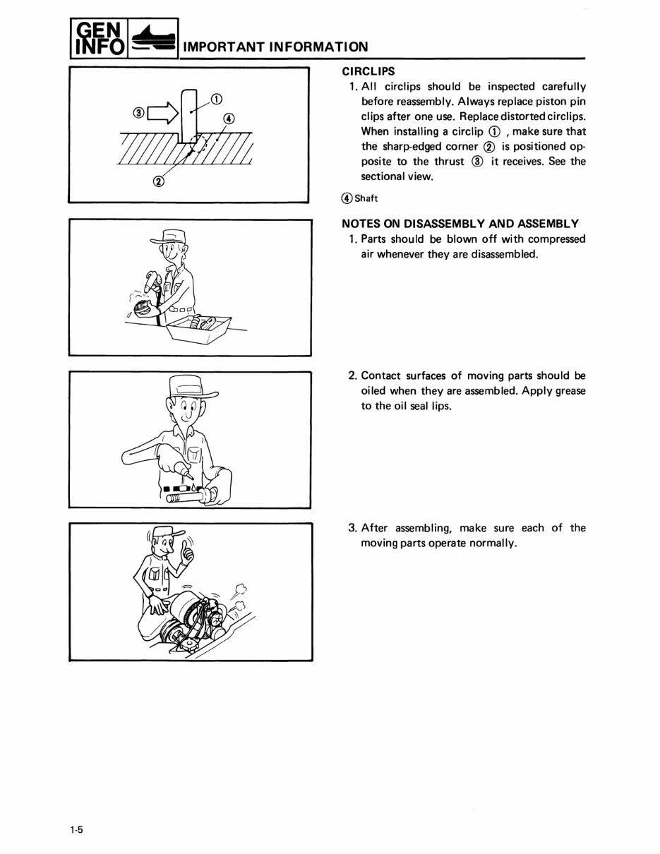
'·5 I IMPORTANT INFORMATION CIRCLIPS 1. All circlips should be inspected carefully before reassembly. Always replace piston pin clips after one use. Replace distorted circlips. When installing a circlip CD , make sure that the sharp-edged corner ® is positioned op- posite to the thrust @ it receives. See the sectional view. @Shaft NOTES ON DISASSEMBLY AND ASSEMBLY 1. Parts should be blown off with compressed air whenever they are disassembled. 2. Contact surfaces of moving parts should be oiled when they are assembled. Apply grease to the oil seal lips. 3. After assembling, make sure each of the moving parts operate normally.
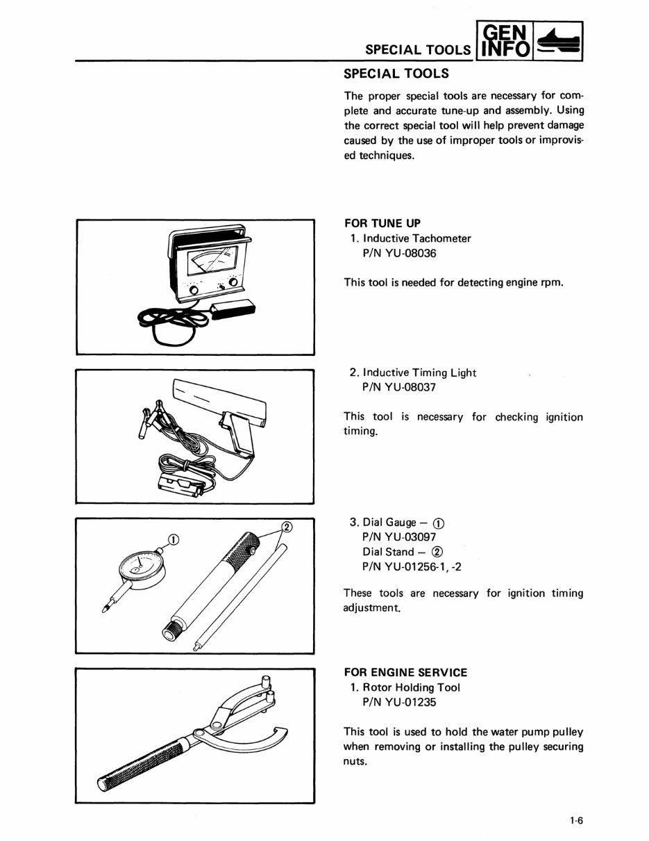
SPECIAL TOOLS I ~1f:~1- SPECIAL TOOLS The proper special tools are necessary for com- plete and accurate tune-up and assembly. Using the correct special tool will help prevent damage caused by the use of improper tools or improvis- ed techniques. FOR TUNE UP 1. I nductive Tachometer PIN YU-08036 This tool is needed for detecting engine rpm. 2. Inductive Timing Light PIN YU-08037 This tool is necessary for checking ignition timing. 3. Dial Gauge - CD PIN YU-03097 Dial Stand - ® PIN YU-01256-1,-2 These tools are necessary for ignition tim ing adjustment. FOR ENGINE SERVICE 1. Rotor Holding Tool PIN YU-01235 This tool is used to hold the water pump pulley when removing or installing the pulley securing nuts. 1-6
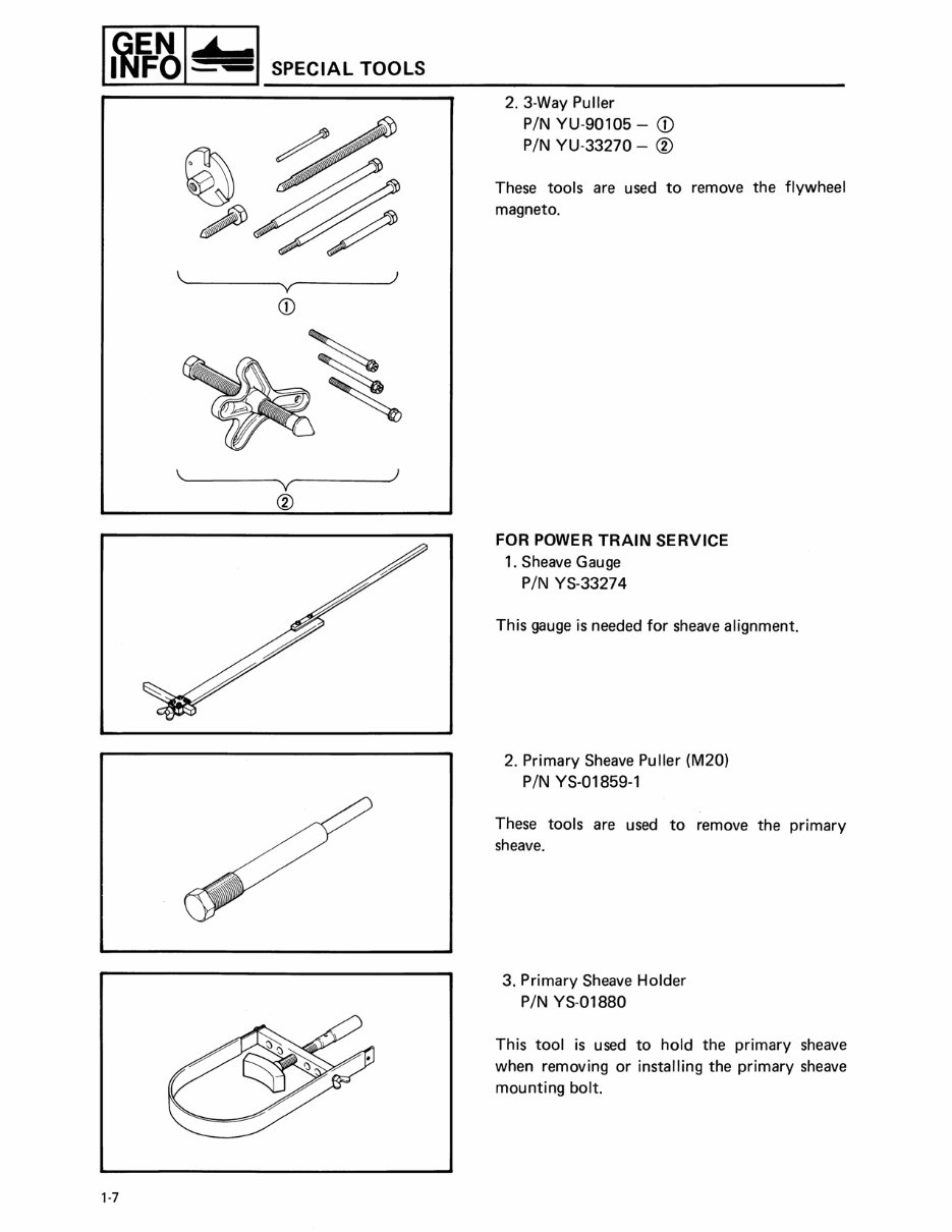
1-7 SPECIAL TOOLS ~~------~ ~------~) v CD ,~------~ ~------~) v ® 2. 3-Way Puller PIN YU-90105 - CD PIN YU-33270 - ® These tools are used to remove the flywheel magneto. FOR POWER TRAIN SERVICE 1. Sheave Gauge PIN YS-33274 This gauge is needed for sheave alignment. 2. Primary Sheave Puller (M20) PIN YS-01859-1 These tools are used to remove the primary sheave . 3. Primary Sheave Holder PIN YS-01880 This tool is used to hold the primary sheave when removing or installing the primary sheave mounting bolt.
IMPROVED manuals provide a range of features including bookmarks, sub bookmarks, an index, and improved quality. These manuals are designed to meet the needs of both professional mechanics and DIY enthusiasts.
With these manuals, you can easily print the pages you need and create a backup CD. They are compatible with all major operating systems including Windows, Mac, and Linux.
The manuals are user-friendly, allowing you to quickly find the information you need without having to dig through hundreds of pages. They are comprehensive factory repair manuals with hundreds of pages of diagrams and instructions, enabling you to disassemble and assemble (overhaul) various components, including the engine.
The manual covers models such as the Yamaha Snowmobile 1988, 1989, and 1990, including the Enticer LTR 340/400, ET400TR, and ET340.
The content of the manual includes general information, periodic maintenance/tune-up, engine/transmission, fuel/lubrication/cooling, electrical system, drive system, suspension, steering/frame, controls/indicators, aids for maintenance, troubleshooting, wiring diagrams, and much more.
If you have any questions or hesitations, feel free to contact us for immediate assistance.

![YAMAHA Snow le 1988-1990 Enticer 340 400 LTR Service Repair Manual [IMPROVED]](https://cdm.emanualonline.com/media/catalog/product/cache/518e89fe08903fc357b0d05eb410bb22/1/0/107264-2.jpg "YAMAHA Snow le 1988-1990 Enticer 340 400 LTR Service Repair Manual [IMPROVED]")