• • Quick Reference Guide S "f" " peci Icatlons ....... .. ...... .... .... .. ................................... " ... .. .. ........................... . Maintenance and Theory ........................................................................... . Repair ...................................................................... ...................................... . Appendix .......................................... .. .............................. .. ............. .. .......... ... Using the quick reference guide will assist you in quickly locating a desired topic or procedure contained with in this shop manual. Bend the pages back unt il you match the de- sired section above with the black tab on the right hand side of the table of contents for that section. Refer to the table of contents for the exact page(s) to locate the spec i fic topic or procedure required. SECTION QUICK REFERENCE GUIDE ii
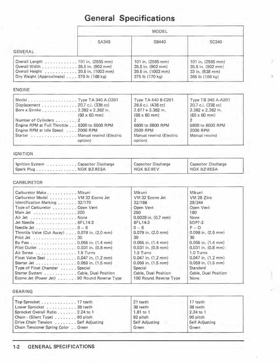
General Specifications SA340 GENERAL Overall Length .. .. .. . ... .. 101 in. (2565 mm) Overall Width ........... .. 35.5 in. (902 mm) Overall Height ... .. ... .... 39.5 in. (1003 mm) Dry Weight (Approximate) ... . 370 Ib (168 kg) ENGINE Model ..... ..... .... .... Type T A 340 A · D201 Displacement ...... . ...... 20.7 c.i. (338 cc) Bore x Stroke ............. 2.362 x 2.362 in. (60 x 60 mm) Number of Cylinders .. ...... 2 Engine RPM at Full Throttle . . . 6300 to 6500 RPM Engine RPM at Idle Speed .... 2000 RPM Starter ................. Manual rewind (Electric option) IGNITION Ignition System . . ... .... .. Capacitor Discharge Spark Plug . . .. .. ...... . .. NGK BZ-8ESA CARBURETOR Carburetor Make . .. .. ...... Mikuni Carburetor Model .... .... .. VM 32 Econo Jet Identification Marking ....... 32/170 Type of Carburetor ......... Open Vent Main Jet ................ 200 Air Jet ... ............ .. None Jet Needle .. ............. 6FL14-3 Needle Jet ............. .. 0 - 6 Throttle Valve (Cut Away) .... 0.079 in. (2.0 mm) Pilot Jet ... .. ... ........ 30 By Pass . ......... . ... . . . 0.055 in. (1.4 mm) Pilot Outlet ..... . ..... . . . 0.031 in. (0.8 mm) Air Screw .............. . 1.5 Turns Float Valve Seat .. . ........ 0.047 in . (1.2 mm) Starter Jet ....... .. ...... 0.059 in. (1.5 mm) Type of Float Chamber . .... . Special Starter System .... _ ....... Cable, Dual Position Econo Jet (Power Jet) ... .. .. 90 Round Reverse Type GEARING Top Sprocket . ........ .. . . 17 teeth Lower Sprocket .... ..... .. 38 teeth Sprocket Overall Ratio ... .... 2.24 to 1 Chain - (Silent Type) ........ 90 pitch Drive Chain Tension ..... ... Se lf Adjusting Chain Tensioner Spring Color .. Green 1-2 GENERAL SPECIFICATIONS MODEL SB440 101 in. (2565 mm) 35.5 in. (902 mm) 39.5 in. (1003 mm) 375 Ib (170 kg) Type T A 440 B-C20 1 26.6 c.i. (436 cc) 2.677 x 2.362 in. (68 x 60 mm) 2 6600 to 6800 RPM 2500 RPM Manual rewind (Electric option) Capacitor Discharge NGK BZ-9EV Mikuni VM 32 Econo Jet 32 /1 66 Open Vent 250 0.0028 in. (0.7 mm) 6FL 14-3 0- 6 0.079 in. (2.0 mm) 30 0.055 in. (1.4 mm) 0.03 1 in. (0.8 mm) 1.5 Turns 0.047 in. (1.2 mm) 0.059 in. (1.5 mm) Special Cable, Dual Position 100 Round Reverse Type 21 teeth 38 teeth 1.81 to 1 92 pitch Se lf Adjusting Green SC340 101 in. (2565 mm) 35.5 in. (902 mm) 33 in. (838 mm) 3651b (166 kg) Type TB 340 A-A201 20.7 c. i. (338 cc) 2.362 x 2.362 in. (60 x 60 mm) 2 5800 to 6000 RPM 2000 RPM Manual rewind Capacitor Discharge NGK BZ-8ESA Mikuni VM 28 Zinc 28 /344 Open Vent 180 None 5DP7 -3 P- 0 0.098 in. (2.5 mm) 30 0.055 in. (1.4 mm) 0.031 in. (0.8 mm) 1.0 Turns 0.047 in. (1.2 mm) 0.059 in. (1.5 mm) Standard Cab le, Dual Position None 17 teeth 38 teeth 2.24 to 1 90 pitch Self Adjusting Green ,. 1
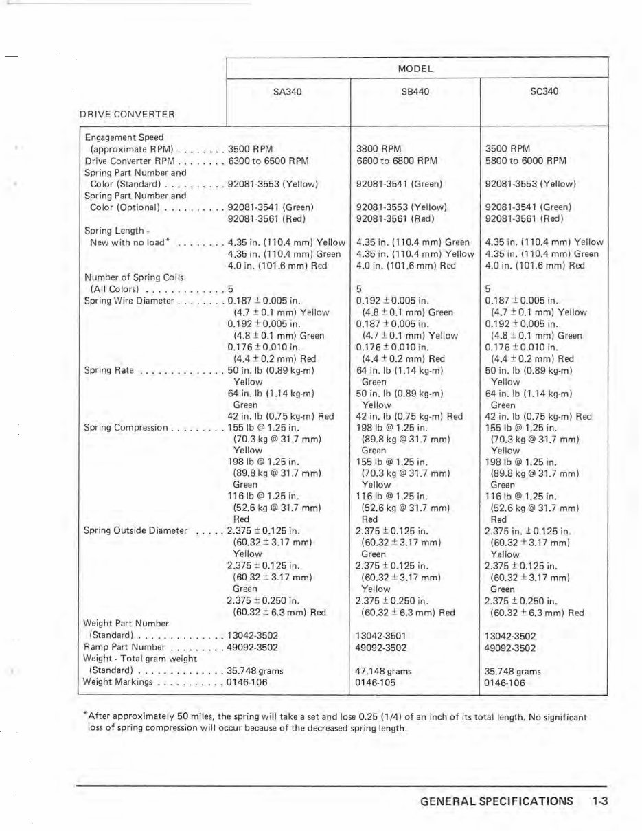
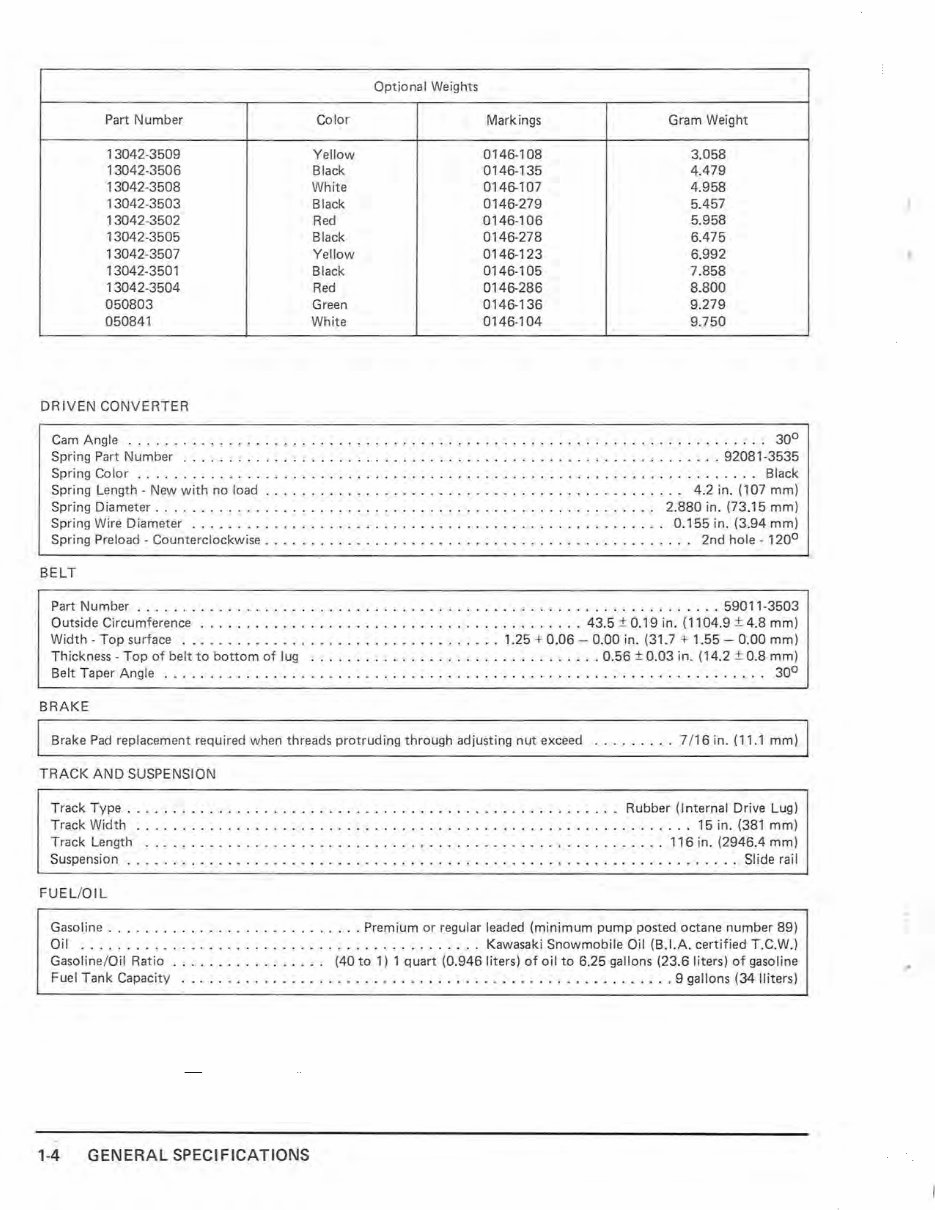
• " SA340 DRIVE CONVERTER Engagement Speed (approximate RPM) ........ 3500 RPM Drive Converter RPM . .. ..... 6300 to 6500 RPM Spring Part Number and Color (Standard) ...... .. .. 92081-3553 (Yellow) Spr i ng Part Number and Color (Optional) .... .... . .. 92081-3541 (Green) 92081-3561 (Red) Spri ng Length - New with no load* ...... . . 4.35 in. (110.4 mm) Yellow 4.35 in. (110.4 mm) Green 4.0 in. (101.6 mm) Red Number of Spring Coils (All Colors) .. .. . .. .. . ... 5 Spring Wire Diameter . ... .... 0.187 ± 0. 005 in. (4.7 ± 0.1 mm) Yellow 0.192 ± 0.005 in. (4 .8 ± 0.1 mm) Green 0.176 ± 0.010 in. (4.4 ± 0.2 mm) Red Spring Rate .. . ... ... . ... . 50 in. Ib (0.89 kg·m) Yellow 64 in. Ib (1.14 kg·m) Gree n 42 in. Ib (0.75 kg-m) Red Spring Compress ion .. . ..... . 155 Ib @ 1.25 in. (70.3 kg @ 31.7 mm) Yellow 1981b @ 1.25 in . (89.8 kg @ 31 .7 mm) Green 116 Ib @ 1.25 in . (52.6 kg @ 31.7 mm) Red Spring Outside D ia meter . . . .. 2.375 ±0.125 in . (60.32 ± 3 .1 7 mm) Yellow Weight Part Number 2.375 ± 0.125 in. (60.32 ± 3.17 mm) Green 2.375 ± 0.250 in. (60.32 ± 6.3 mm) Red (Standard) ..... . .... . ... 13042- 3502 Ramp Part Number . . .. .. ... 49092-3502 Weight - Total gram weight (Standard) . ... ... .... . ... 35.748 grams Weight Markings . .. .. .. .. .. 0146-106 MODEL SB440 3800 RPM 6600 to 6800 RPM 92081-3541 (Green) 92081-3553 (Yellow) 92081 -3561 (Red) 4.35 in. (110.4 mm) Green 4.35 in. (110.4 mm) Yellow 4.0 in. (101.6 mm) Red 5 0.192 ± 0. 005 in . (4.8 ± 0.1 mm) Green 0.187 ± 0.005 in. (4.7±0.1 mm) Yell ow 0.176 ± 0.010 in. (4.4 ± 0.2 mm) Red 64 in . lb (1 .14 kg-m) Green 50 in . Ib (0.89 kg·m) Yellow 42 in. Ib (0.75 kg-m) Red 198 Ib @ 1.25 in. (89.8 kg @ 31.7 mm) Green 1551b @ 1.25 in. (70.3 kg @ 31.7 mm) Yellow 116 Ib @ 1.25 in. (52.6 kg @ 31.7 mm) Red 2.375 ± 0.125 in. (60.32 ± 3.17 mm) Green 2.375 ± 0.125 in. (60.32 ± 3.17 mm) Yellow 2.375 ± 0.250 in. (60.32 ± 6.3 mm) Red 13042-3501 49092-3502 47.148 grams 0146-1 05 SC340 3500 RPM 5800 to 6000 RPM 92081-3553 (Yellow) 92081·3541 (Green) 92081-3561 (Red) 4.35 in. (11 0.4 mm) Yellow 4.35 in. (110.4 mm) Green 4.0 in. (101 .6 mm) Red 5 0.187 ±0.005 in. (4.7 ± 0.1 mm) Ye llow 0.192 ± 0.005 in. (4.8 ± 0.1 mm) Green 0.176 ± 0.010in. (4.4 ± 0.2 mm) Red 50 in. Ib (0 .89 kg-m) Yellow 64 in.lb (1.14 kg-m) Green 42 in. Ib (0.75 kg-m) Red 155 Ib @ 1.25 in. (70.3 kg @ 31.7 mm) Yellow 1981b @ 1.25 in. (89.8 kg @ 31.7 mm) Green 116Ib@1.25in. (52.6 kg @ 31.7 mm) Red 2.375 in. ± 0.125 in. (60.32 ± 3.17 mm) Yellow 2.375 ± 0.125 in. (60.32 ± 3.17 mm) Green 2.375 ± 0.250 in. (60.32 ± 6.3 mm) Red 13042-3502 49092-3502 35.748 grams 0146-106 * After approximately 50 miles, the spring will take a set and lose 0.25 (1 /4) of an inch of its total length. No signi ficant loss of spring compression will occur because of the decreased spring length. GENERAL SPECIFICATIONS 1-3
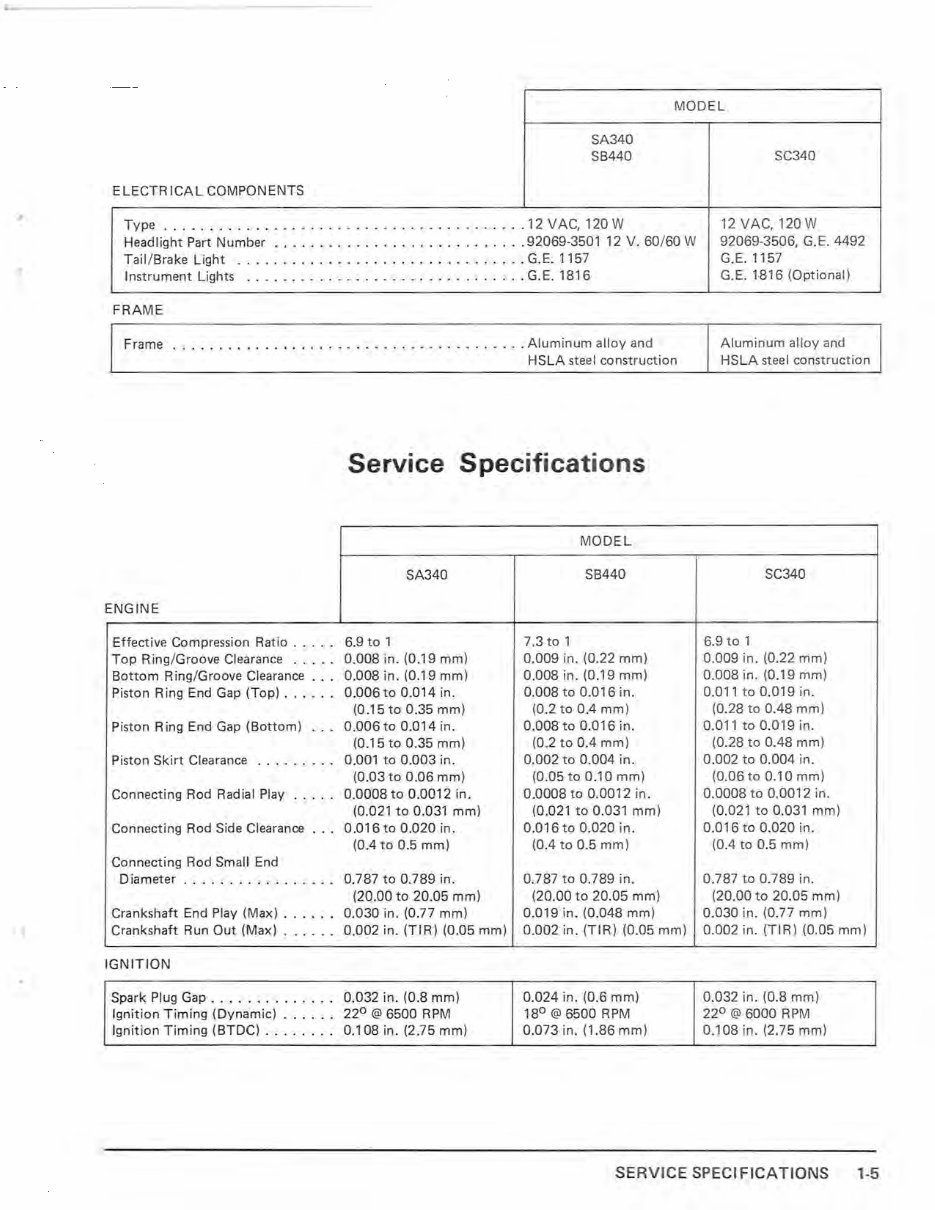
. MODEL SA340 SB440 ElECTR ICAl COMPONENTS Type ..... . ....... .. ........ . ...... ... ...... . 12 VAC, 120 W Headlight Part Number . . . . . . . . . . . . . . . . . . . . . . . . . . . . 92069·3501 12 V. 60/60 W Tail / Brake light . .. .. ... .... . .. . ........... ... .. G.E.1157 Instrument lights .. ...... . ....... . ..... . ..... .. . G.E.1816 FRAME Frame ... . .... . .................. . ........... Aluminum alloy and HSlA steel construction ENGINE Effect ive Compression Ratio . ... . Top Ring/Groove Clearance . . .. . Bottom Ring/Groove Clearance . . . Piston Ring End Gap (Top) . ... . . Piston Ring En d Gap (Bottom) . .. Piston Ski rt Clearance ........ . Connecting Rod Radial Play .. ... Connecting Rod Side Clearance Connecting Rod Small End Diameter . ..... .. ... . . . . . . Crankshaft End Play (Max) . .... . Crankshaft Run Out (M ax ) .... . . IGNITION Spark Plug Gap .... ... .... ... Ignition T iming (Dynamic) ...... Ignition Timing (BTDC) . ... .. .. Service Specificat ions SA340 6.9 to 1 0.008 in. (0.19 mm) 0.008 in. (0.19 mm) 0.006to 0.014 in . (0.15 to 0.35 mm) 0.006 to 0.014 in . (0.15 to 0.35 mm) 0.001 to 0.003 in. (0.03 to 0.06 mm) 0.0008 to 0.0012 in. (0.021 to 0.031 mm) 0.016 to 0.020 in. (004 to 0.5 mm) 0.787 to 0.789 in. (20.00 to 20.05 mm) 0.030 in. (0.77 mm) 0.002 in. (TIR) (0 . 05 mm) 0.032 in. (0.8 mm) 22 0 @ 6500 RPM 0.108 in. (2.75 mm) MODEL SB440 7.3 to 1 0.009 in. (0.22 mm) 0.008 in. (0.19 mm) 0.008 to 0.0 16 in. (0 .2 to 004 mm) 0.008 to 0.016 in. (0.2 to 0.4 mm) 0.002 to 0.004 in. (0.05 to 0.10 mm) 0 .0008 to 0.0012 in. (0.021 to 0 .031 mm) 0.016 to 0.020 in. (004 to 0.5 mm) 0.787 to 0.789 in. (20.00 to 20.05 mm) 0.019 in. (0.048 mm) 0.002 in. (TIR) (0.05 mm) 0.024 in . (0 .6 mm) 18 0 @ 6500 RPM 0.073 in. (1 .86 mm) SC340 12 VAC, 120 W 92069·3506, G. E. 4492 G.E.1157 G.E. 1816 (Optional) Aluminum alloy and HSlA st eel constr uction SC340 6.9 to 1 0.009 in. (0.22 mm) 0.008 in. (0.19 mm) 0.011 to 0.019 in. (0.28 to 0.48 mm) 0.011 to 0.019 in. (0.28 to 0.48 mm) 0.002 to 0.004 in. (0.06to 0.10 mm) 0.0008 to 0.0012 in. (0.021 to 0.031 mm) 0.016 to 0.020 in. (004 to 0.5 mm) 0.787 to 0.789 in. (20.00 to 20.05 mm) 0.030 in. (0.77 mm) 0.002 in. (TIR) (0.05 mm) 0.032 in. (0.8 mm) 22 0 @ 6000 RPM 0.108 in. (2.75 mm) SERVICE SPECIFICATIONS 1-5
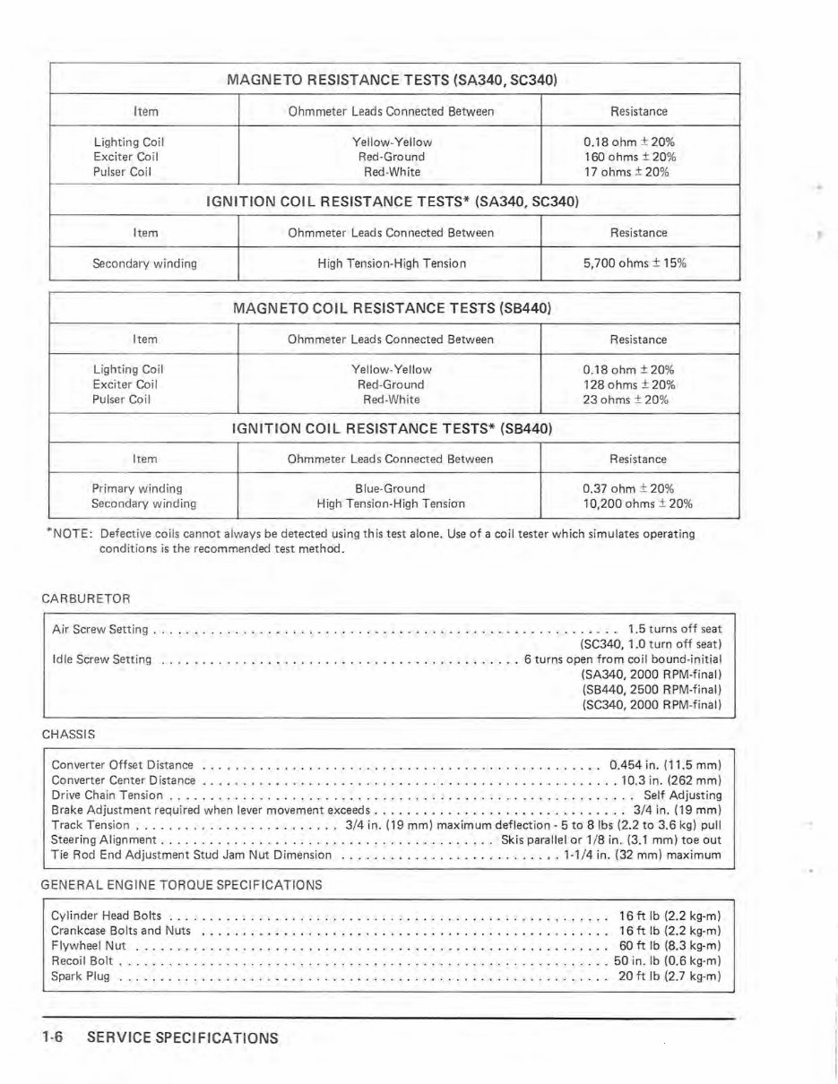
MAGNETO RESISTANCE TESTS (SA340, SC340) Item Ohmmeter Leads Connected Between Resistance Lighting Co il Yellow- Yellow 0.18 ohm ± 20% Exci ter Coil Red -Ground 160 ohms ± 20% Pulser Co il Red-White 17 ohms ± 20% IGNITION COIL RESISTANCE TESTS* (SA340, SC340) Item Ohmmeter Lea ds Connected Between Resistance Sec ondary winding High Tension-High Tension 5,700 ohms ± 15% MAGNETO COIL RESISTANCE TESTS (S8440) Item Ohmmeter Leads Connected Between Resistance Lighting Co il Yellow-Yellow 0.18 ohm ± 20% Exciter Coi I Red-Ground 128 ohms ± 20% Pu lser Coil Red-White 23 ohms ± 20 % IGNITION COIL RESISTANCE TESTS* (S8440) Item Ohmmeter Leads Connected Between Resistance Primary winding Blue-Ground 0.37 ohm ± 20% Secondary winding High Tension-H igh Tension 10,200 ohms ± 20% *N OTE: Defective coils cannot always be detected using this test alone. Use of a coil tester which simulates operating conditions is the re commended test method. CARBURETOR Air Screw Setting . . ........ .... . .... ..... ........... . ............... . .... _ 1.5 turns off seat (SC340, 1.0 turn off seat) Idle Screw Sett ing ... .. .. .. .. .. ..... ... .. .................... . 6 turns open from coil bound-initial CHASSIS (SA340, 2000 RPM-final) (SB440, 2500 RPM-final) (SC340, 2000 RPM-fina l ) Converter Offset Distance ..... .. ... ... .. . ....... .. ... ... .. ..... ....... .. .. 0.454 in. (11.5 mm) Converter Center Distance .. . ............... . ........ .. .... .... .... .. .. .. .. . . 10.3 in. (262 mm) Drive Chain Tension . . . . . . . . . . . . . . . . . . . . . . . . . . . . . . . . . . . . . . . . . . . . . . . . . . . . . . . .. Self Adjusting Brake Adjustment requir ed when lever movement exceeds . .... . ................ .. ...... . 3/4 in. (19 mm) T rack Tension ... . ...... . .... .. ...... . . 3/4 in. (19 mm) maximum deflection -5 to 8 Ibs (2.2 to 3.6 kg) pull Steering Alignment . ......... . .. . ..... .. ... ... . ..... . .. ... .. Sk is parallel or 1/8 in. (3.1 mm) toe out Tie Rod End Adjustment Stud Jam Nut Dimension ........ .. ... . .......... . .. 1-1/4 in. (32 mm) maximum GENERAL ENGINE TORQUE SPEC IFI CATIONS Cylinder Head Bo lts . .. . . . . . . . . . . . . . . . . . . . . . . . . . . . . . . . . . . . . . . . . . . . . . . . . . . . 16 ft Ib (2.2 kg-m) Crankcase Bolts and Nuts ..... .. ................................... .. .. .... 16 ft Ib (2.2 kg-m) Flywheel Nut . . . . . . . . . . . . . . . . . . . . . . . . . . . . . . . . . . . . . . . . . . . . . . . . . . . . . . . . .. 60 ft Ib (8.3 kg-m) Recoil Bolt .. .. ...... . ....... .. ... ... .......... . ... .. ......... . .. ... ... 50 in. Ib (0.6 kg-m) Spark Plug ... . ... . . . . . . . . . . . . . . . . . . . . . . . . . . . . . . . . . . . . . . . . . . . . . . . . . . . . . 20 ft Ib (2.7 kg-m) 1-6 SERV IC E SPEC I FI CAT IO NS ..
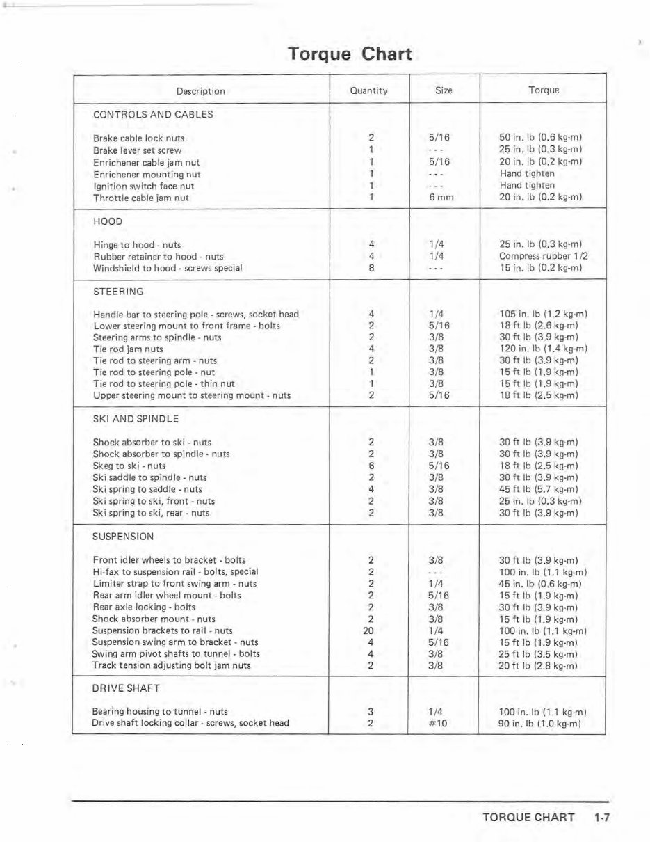
Torque Chart Descr i ption Quantity Size Torque CONTROLS AND CAB L ES Brake cable lock nuts 2 5/ 16 50 in. Ib (0 .6 kg-m) • Brake lever set screw 1 - -- 25 in. Ib (0.3 kg-m) Enrichenercable ja m nut 1 5 /1 6 20 in. Ib (0.2 kg-m) Enrichener mounting nut 1 - - - Hand tighten Ignition switch face nut 1 - - - Hand tighten T hrottle cable jam nut 1 6mm 20 in. Ib (0.2 kg-m) HOOD Hinge to hood - nuts 4 1/4 25 in. Ib (0.3 kg -m ) Rubber retainer to hood - nuts 4 1/4 Compress rubber 1/2 Windshield to hood - screws special 8 - - - 15 in. Ib (0.2 kg-m) STEERING Handle bar to steering pole - screws, socket head 4 1/4 105 in. Ib (1.2 kg-m) Lower steering mount to front frame - bolts 2 5 /16 18 ft Ib (2.6 kg-m) Steering arms to spindle - nuts 2 3/8 30 ft Ib (3.9 kg-m) Tie rod jam nuts 4 3 /8 120 in. Ib (1.4 kg-m) Tie rod to steering arm - nuts 2 3 /8 30 ft Ib (3.9 kg-m) Tie rod to steering pole - nut 1 3/8 15 ft Ib (1.9 kg-m) Tie rod to steering pole - thin nut 1 3/8 15 ft Ib (1.9 kg-m) Upper steering mount to steering mount - nuts 2 5/16 18 ft Ib (2.5 kg-m) SKI AND SP INDL E Shock absorber to ski - nuts 2 3/8 30 ft Ib (3.9 kg-m) Shock absorber to spindle - nuts 2 3/8 30 ft Ib (3.9 kg-m) Skeg to ski - nuts 6 5 /16 18 ft Ib (2.5 kg -m) Ski saddle to sp indle - nuts 2 3/8 30 ft Ib (3.9 kg-m) Ski spring to sadd le - nuts 4 3/8 45 ft Ib (5.7 kg -m) Ski spring to ski, front - nuts 2 3/8 25 in. Ib (0.3 kg -m) Sk i spring to ski, rear - nuts 2 3/8 30 ft Ib (3.9 kg-m) SUSPENSION Front idl er wheels to bracket - bolts 2 3/8 30 ft Ib (3.9 kg-m) Hi-fax to suspension rail - bolts, special 2 --- 100 in. Ib (1.1 kg-m) Limiter strap to front swing arm - nuts 2 1/4 45 in . Ib (0 .6 kg -m) Rear arm idler wheel mount - bolts 2 5/ 16 15 ft Ib (1.9 kg-m) Rear axle lo ck ing - bolts 2 3/8 30 ft Ib (3.9 kg-m) Shock absorber mount - nuts 2 3 /8 15 ft Ib (1.9 kg-m) Suspension brackets to rail - nuts 20 1/4 100 in. Ib (1.1 kg -m) Suspension swing arm to bracket - nuts 4 5 /16 15 ft Ib (1.9 kg-m) Swing arm pivot shafts to tunnel - bolts 4 3 /8 25 ft Ib (3.5 kg-m) Track ten s ion adjusting bolt jam nuts 2 3/8 20 ft Ib (2.8 kg-m) DRIVE SHAFT Bearing housing to tunnel - nuts 3 1/4 100 in. Ib (1.1 kg - m) Drive shaft locking collar - screws, socket head 2 #10 90 in. Ib (1.0 kg -m) TORQUE CHART 1-7
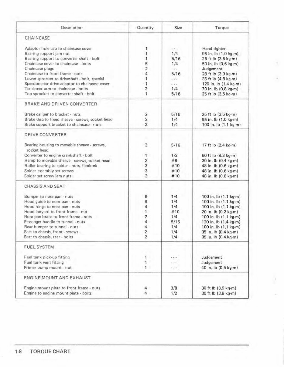
Description Quantity Size Tor que CHAINCASE Adaptor hole cap to chaincase cover 1 - -- Hand tighten Bearing support jam nut 1 1/ 4 95 in. Ib (1 .0 kg-m) Bearing support to converter shaft - bolt 1 5 /1 6 25 ft Ib (3.5 kg-m) Chaincase cover to chaincase - bolts 5 1/4 50 in. Ib (0.6 kg-m) Chaincase plugs 2 - -- Judgement Chaincase to front frame - nuts 4 5/1 6 28 ft Ib (3.9 kg-m) Lower sprocket to driveshaft - bolt, special 1 - -- 35 ft Ib (4.8 kg-m) Speedometer drive adaptor to ch aincase cover 1 - -- 120 in.lb (1.4 kg-m) Tensioner arm to chaincase - bolts 2 1/4 70 in. Ib (0.8 kg-m) Top sprocket to converter shaft - bolt 1 5 11 6 25 ft Ib (3.5 kg-m) BRAKE AND DR IV EN CONVERTER Brake ca liper to bracket - nuts 2 5/ 16 25 ft Ib (3.5 kg-m) Brake disc to fixed sheave - screws, so ck et head 3 1/4 95 in. Ib (1 .0 kg-m) Brake support bracket to chaincase - nuts 2 1/4 100 in.lb (1.1 kg-m) DRIVE CONVERTER Bearing housing to movable sheave - screws, 3 5/16 17 ft Ib (2.4 kg-m) socket head Converter to engine crankshaft - bolt 1 1/2 60 ft Ib (8.3 kg-m) Ramp to movable sheave - screws, soc ket head 3 #8 30 in. Ib (0.4 kg-m) Roller bearing to spider - nuts, flexlock 3 # 10 48 in. Ib (0.6 kg -m) Spider assembly set screws 3 # 10 48 in. Ib (0.6 kg-m) Spider set screw jam nuts 3 #10 48 in . Ib (0.6 kg-m) CHASSIS AND SEAT Bumper to nose pan - nuts 6 1/4 100 in. Ib (1.1 kg-m) Hood guide to nose pan - nuts 8 1/ 4 100 in. Ib (1.1 kg-m) Hood hinge to nose pan - nuts 4 1/4 100 in. Ib (1.1 kg-m) Hood lanyard to front frame - nut 1 #10 20 in. Ib (0.2 kg-m) Nose pan brace to front frame - nuts 2 1/4 100 in. Ib (1.1 kg-m) Passenger handle to tunnel - nuts 4 5/ 16 120 in. Ib (1.4 kg-m) Rear bumper to tunnel - nuts 4 1/ 4 100 in. Ib (1.1 kg-m) Seat to chassis, front - screws 2 1/ 4 35 in. Ib (0.4 kg -m) Seat to chassis, rear - bolts 2 1/4 35 in. Ib (0.4 kg-m) FU EL SYSTEM Fuel tank pick-up fitting 1 - -- Judgement Fuel tank vent fitting 1 - -- Judgement Primer pump mount - nut 1 - -- 40 in. Ib (0.5 kg-m) ENGINE MOUNT AND EXHAUST Engine mount plate to front frame - nuts 4 3/8 30 ft Ib (3.9 kg-m) Engine to engine mount plate - bolts 4 1/2 30 ft Ib (3.9 kg-m) 1-8 TORQUE CHART
This manual is a comprehensive guide for the 1980 KAWASAKI DRIFTER 440, providing detailed instructions for maintenance and repair tasks. It is suitable for both professional mechanics and DIY enthusiasts. With hundreds of pages, it covers a wide range of topics, from basic maintenance such as oil changes to more complex procedures like transmission swaps. The manual includes numerous illustrations and easy-to-understand text to assist you throughout the process. Additionally, it features a search function for easy navigation and the option to print specific pages. Whether you are looking to maintain or repair your machine, this Factory Service Repair Manual will equip you with the necessary knowledge. Visit www.johnsmanuals.com for more service manuals.