2003-2008 Yamaha Raptor 80 YFM80 Service & Repair Manual
What's Included?
Lifetime Access
Fast Download Speeds
Online & Offline Access
Access PDF Contents & Bookmarks
Full Search Facility
Print one or all pages of your manual
YFM80WP SUPPLEMENTARY SERVICE MANUAL LIT-11616-15-38 4EM-28197-22
FOREWORD This Supplementary Service Manual has been prepared to introduce new service and new data for the YFM80WP. For complete information on service procedures, it is necessary to use this Supple- mentary Service Manual together with the following manual. YFM80(D) SERVICE MANUAL: 4EM-28197-20 (LIT-11616-08-19) YFM80M/MC SUPPLEMENTARY SERVICE MANUAL: 4EM-28197-21 (LIT-11616-13-28) YFM80WP SUPPLEMENTARY SERVICE MANUAL 2001 by Yamaha Motor Corporation, U.S.A. First Edition, September 2001 All rights reserved. Any reproduction or unauthorized use without the written permission of Yamaha Motor Corporation, U.S.A. is expressly prohibited. Printed in U.S.A. LIT-11616-15-38
EB001000 NOTICE This manual was produced by the Yamaha Motor Company primarily for use by Yamaha dealers and their qualified mechanics. It is not possible to include all the knowledge of a mechanic in one manual, so it is assumed that anyone who uses this book to perform maintenance and repairs on Yamaha machine has a basic understanding of the mechanical ideas and the procedures of machine repair. Repairs attempted by anyone without this knowledge are likely to render the machine unsafe and unfit for use. Yamaha Motor Company, Ltd. is continually striving to improve all its models. Modifications and sig- nificant changes in specifications or procedures will be forwarded to all authorized Yamaha dealers and will appear in future editions of this manual where applicable. NOTE: Designs and specifications are subject to change without notice. IMPORTANT INFORMATION Particularly important information is distinguished in this manual by the following notations. The Safety Alert Symbol means ATTENTION! BECOME ALERT! YOUR SAFETY IS INVOLVED! Failure to follow WARNING instructions could result in severe injury or death to the machine operator, a bystander or a person inspecting or repairing the machine. A CAUTION indicates special precautions that must be taken to avoid dam- age to the machine. A NOTE provides key information to make procedures easier or clearer. WARNING CAUTION: NOTE:
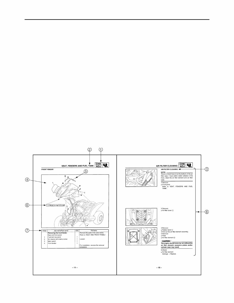
EB002000 HOW TO USE THIS MANUAL MANUAL ORGANIZATION This manual consists of chapters for the main categories of subjects. (See “Illustrated symbols”) 1st title 1: This is the title of the chapter with its symbol in the upper right corner of each page. 2nd title 2: This title indicates the section of the chapter and only appears on the first page of each section. It is located in the upper left corner of the page. 3rd title 3: This title indicates a sub-section that is followed by step-by-step procedures accompa- nied by corresponding illustrations. EXPLODED DIAGRAMS To help identify parts and clarify procedure steps, there are exploded diagrams at the start of each removal and disassembly section. 1. An easy-to-see exploded diagram 4 is provided for removal and disassembly jobs. 2. Numbers 5 are given in the order of the jobs in the exploded diagram. A number that is enclosed by a circle indicates a disassembly step. 3. An explanation of jobs and notes is presented in an easy-to-read way by the use of symbol marks 6. The meanings of the symbol marks are given on the next page. 4. A job instruction chart 7 accompanies the exploded diagram, providing the order of jobs, names of parts, notes in jobs, etc. 5. For jobs requiring more information, the step-by-step format supplements 8 are given in addition to the exploded diagram and the job instruction chart.
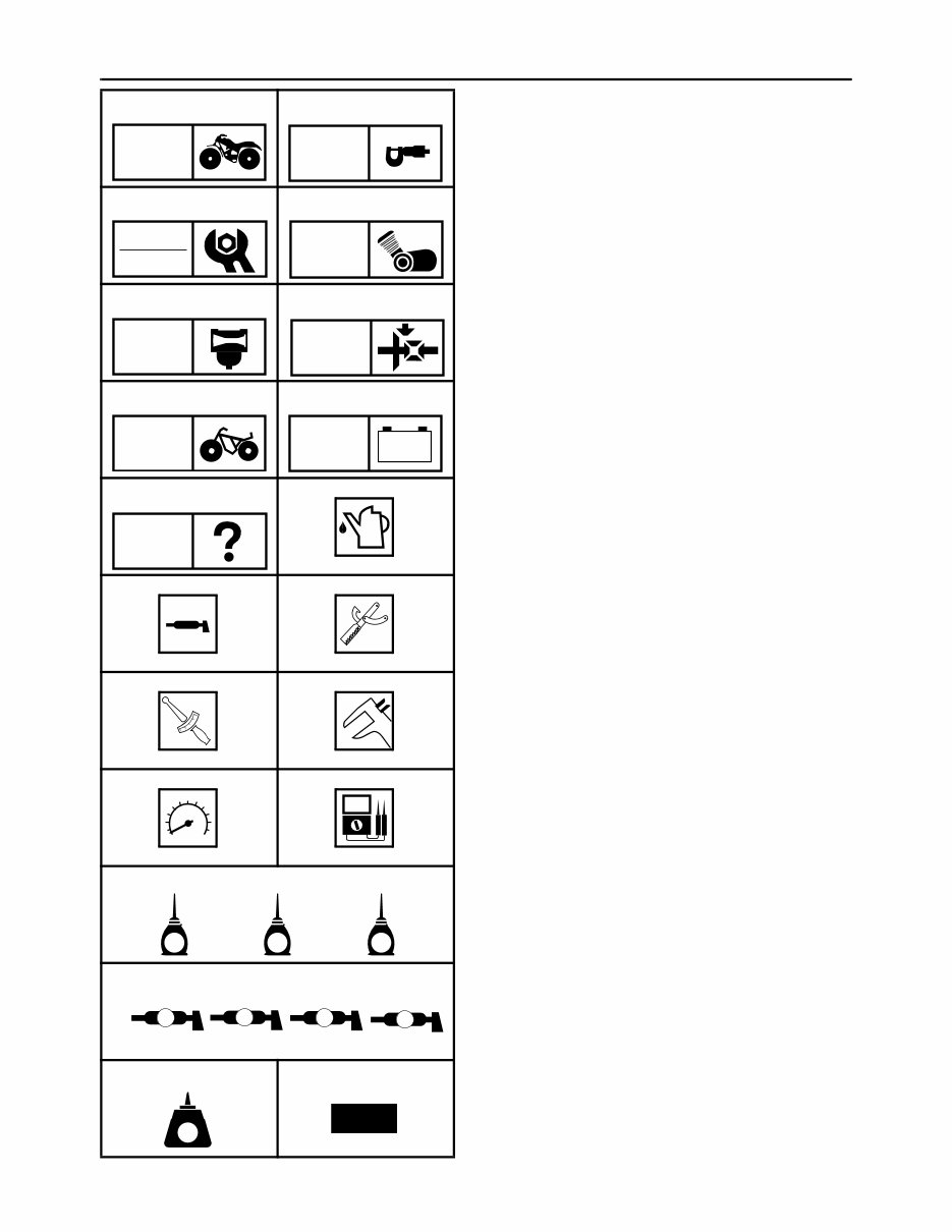
EB003000 ILLUSTRATED SYMBOLS Illustrated symbols 1 to 9 are printed on the top right of each page and indicate the subject of each chapter. 1 General information 2 Specifications 3 Periodic checks and adjustments 4 Engine 5 Carburetion 6 Drive train 7 Chassis 8 Electrical 9 Troubleshooting Illustrated symbols 0 to F are used to identify the specifications appearing in the text. 0 Filling fluid A Lubricant B Special tool C Torque D Wear limit, clearance E Engine speed F Ω, V, A Illustrated symbols G to M in the exploded diagrams indicate the types of lubricants and lubrication points. G Apply engine oil H Apply gear oil I Apply molybdenum disulfide oil J Apply wheel bearing grease K Apply lightweight lithium soap base grease L Apply molybdenum disulfide grease M Apply silicon grease Illustrated symbols N to O in the exploded diagrams indicate where to apply a locking agent N and when to install a new part O. N Apply the locking agent (LOCTITE ) O Replace 1 2 3 4 5 6 7 8 9 0 A B C D E F G H I J N O GEN INFO SPEC CHK ADJ ENG CARB DRIV CHAS – + ELEC TRBL SHTG T R . . E G M B LS M S K L M LT New
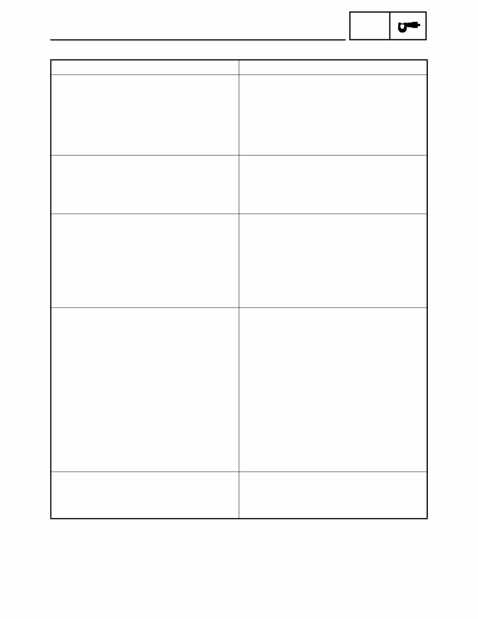
CONTENTS GENERAL INFORMATION .............................................................................. 1 MACHINE IDENTIFICATION ................................................................... 1 VEHICLE IDENTIFICATION NUMBER ................................................ 1 MODEL LABEL .................................................................................... 1 SPECIFICATIONS ........................................................................................... 2 GENERAL SPECIFICATIONS ................................................................. 2 MAINTENANCE SPECIFICATIONS ........................................................ 3 ENGINE ................................................................................................ 3 CHASSIS .............................................................................................. 3 ELECTRICAL ....................................................................................... 4 CABLE ROUTING .................................................................................... 5 PERIODIC CHECKS AND ADJUSTMENTS ................................................... 9 INTRODUCTION ...................................................................................... 9 PERIODIC MAINTENANCE/LUBRICATION INTERVALS ....................... 9 SEAT, FENDERS AND FUEL TANK ...................................................... 10 SEAT AND FRONT PANEL ............................................................... 10 FRONT FENDER ............................................................................... 11 REAR FENDER .................................................................................. 12 FUEL TANK ........................................................................................ 13 ENGINE .................................................................................................. 14 SPEED LIMITER ADJUSTMENT ....................................................... 14 AIR FILTER CLEANING ..................................................................... 15 SPARK ARRESTER CLEANING ....................................................... 17
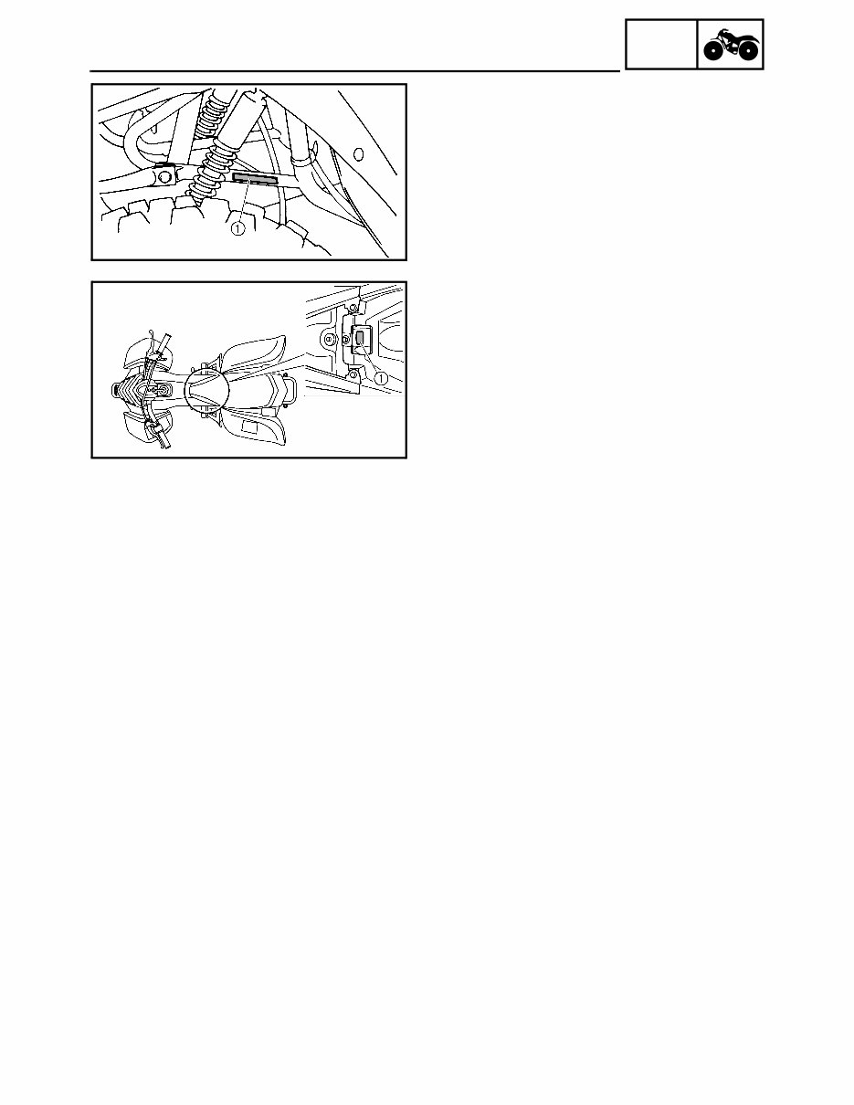
– 1 – GEN INFO MACHINE IDENTIFICATION GENERAL INFORMATION MACHINE IDENTIFICATION VEHICLE IDENTIFICATION NUMBER The vehicle identification number 1 is stamped into the left side of the frame. MODEL LABEL The model label 1 is affixed to the frame. This information will be needed to order spare parts.
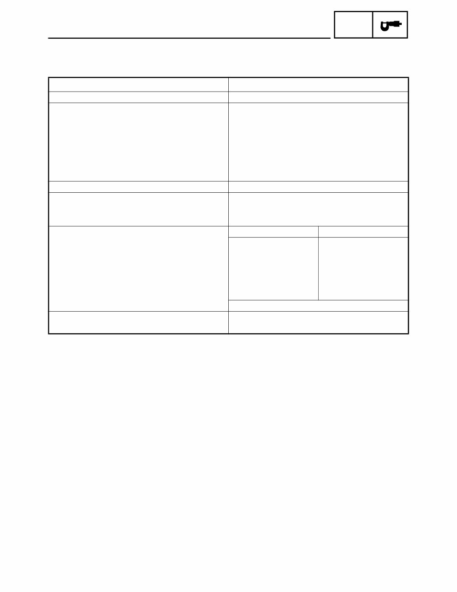
– 2 – SPEC GENERAL SPECIFICATIONS SPECIFICATIONS GENERAL SPECIFICATIONS Model YFM80WP Model code number: 5TH1 Dimensions: Overall length 1,537 mm (60.5 in) Overall width 841 mm (33.1 in) Overall height 940 mm (37 in) Seat height 669 mm (26.3 in) Wheelbase 1,030 mm (40.6 in) Minimum ground clearance 100 mm (3.9 in) Minimum turning radius: 2,400 mm (94.5 in) Spark plug: Type/Manufacturer CR7HS (NGK) Gap 0.6 ~ 0.7 mm (0.024 ~ 0.028 in) Tire pressure (cold tire): Front Rear Recommended 20 kPa (0.20 kg/cm 2 , 2.8 psi) 20 kPa (0.20 kg/cm 2 , 2.8 psi) Minimum 17 kPa (0.17 kg/cm 2 , 2.4 psi) 17 kPa (0.17 kg/cm 2 , 2.4 psi) Maximum 23 kPa (0.23 kg/cm 2 , 3.2 psi) 23 kPa (0.23 kg/cm 2 , 3.2 psi) Maximum load-except motorcycle 95 kg Indicator light wattage × quantity: “NEUTRAL” 12 V 1.7 W × 1
– 3 – SPEC MAINTENANCE SPECIFICATIONS MAINTENANCE SPECIFICATIONS ENGINE CHASSIS Model YFM80WP Carburetor: Type/manufacturer/quantity VM16SH/MIKUNI/1 I. D. mark 5TH1 00 Main jet (M.J.) #76.3 Main air jet (M.A.J.) ø1.2 Jet needle-clip position (J.N.) 3PZ 13-2 Needle jet (N.J.) D-8M Cutaway (C.A.) 3.5 Pilot jet (P.J.) #12.5 Pilot outlet (P.O.) ø0.7 Valve seat (V.S.) ø1.2 Fuel level (F.L.) 2.5 ~ 4.5 mm (0.10 ~ 0.18 in) Below carburetor body edge Float height (F.H.) 20.0 ~ 22.0 mm (0.79 ~ 0.87 in) Engine idling speed 1,750 ~ 1,850 r/min Intake vacuum 36 kPa (270 mmHg) Model YFM80WP Brake lever & brake pedal: Brake lever free play (front brake) 10 ~ 12 mm (0.4 ~ 0.5 in) at lever pivot Brake lever free play (rear brake) 5 ~ 8 mm (0.20 ~ 0.31 in) at lever pivot Brake pedal free play 20 ~ 30 mm (0.8 ~ 1.2 in)
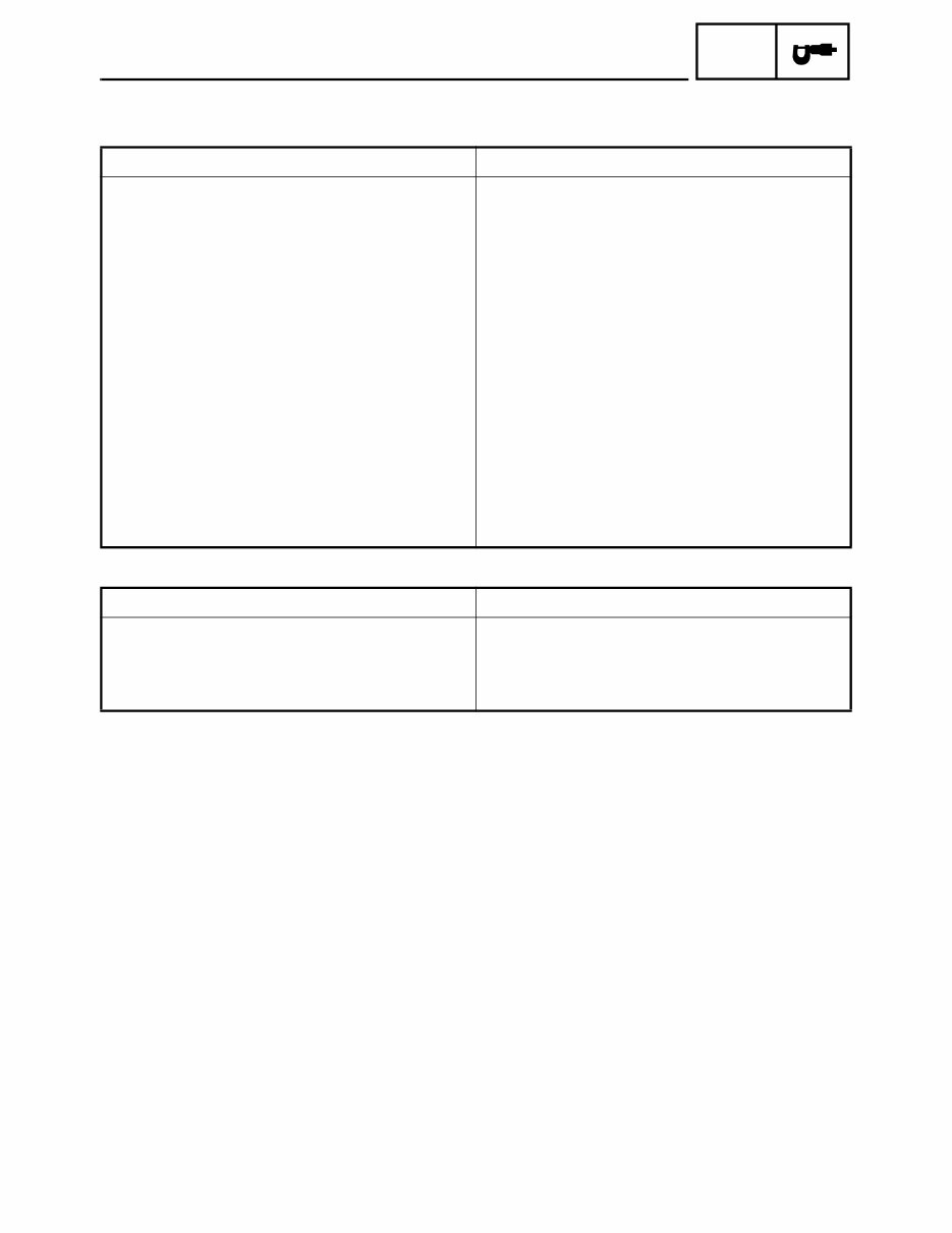
– 4 – SPEC MAINTENANCE SPECIFICATIONS ELECTRICAL Model YFM80WP CDI: Magneto model/manufacturer F2FM/MORIC Pickup coil resistance (color) 264 ~ 396 Ω at 20°C (68°F) (W/L–W/R) Source coil resistance (color) 304 ~ 456 Ω at 20°C (68°F) (G/W–B/R) Lighting coil resistance (color) 0.72 ~ 1.08 Ω B–W 0.32 ~ 0.48 Ω B–Y/R CDI unit model/manufacturer 4EM/MORIC Ignition coil: Model/manufacturer 2JN/MORIC Minimum spark gap 6 mm (0.24 in) Primary winding resistance 0.184 ~ 0.276 Ω at 20°C (68°F) Secondary winding resistance 6.32 ~ 9.48 Ω at 20°C (68°F) Rectifier/regulator: Type Semi conductor-short circuit Model/manufacturer SH704-12/SHINDENGEN No load regulated voltage (DC) 14 ~ 15 V (AC) 13 ~ 14 V Capacity (DC) 5 A (AC) 8 A Withstand voltage 200 V Electric starter system: Type Constant mesh type Starter motor: Model/manufacturer ADB4A5/DENSO Out put 0.2 kW Armature coil resistance 0.0288 ~ 0.0352 Ω at 20°C (68°F) Brush: Overall length 6 mm (0.24 in) <Limit> <3.5 mm (0.14 in)> Spring pressure 3.24 ~ 4.22 N (330 ~ 430 gf) Commutator: Diameter 16.5 mm (0.65 in) <Wear limit> <15.5 mm (0.61 in)> Mica undercut 1.0 mm (0.04 in) Starter relay: Model/manufacturer MS5D-611/JIDECO Amperage rating 100A Coil winding resistance 3.87 ~ 4.73 Ω at 20°C (68°F) Starting circuit cut-off relay: Model/manufacturer ACA12115-3/MATSUSHITA Coil winding resistance 72 ~ 88 Ω at 20°C (68°F) Diode Yes
This is the full Yamaha RAPTOR 80 YFM80 Workshop Service Manual for years 2003-2008. It includes the (156) page Owners manual detailing all normal Maintenance Procedures and ATV functions. The RAPTOR 80 SERVICE MANUAL is (244) pages of Detailed Pictures, Diagrams, and Procedures covering the RAPTOR 80 ATV comprehensively. This Repair Manual also includes the (2) individual Service Supplements to cover all years of the Yamaha RAPTOR 80 correctly. The RAPTOR 80 Service Manual is fully INDEXED and BOOKMARKED by topic, allowing for quick searches to find what you need. It is of Perfect Quality, and you can print the entire manual or select specific pages. Additionally, you can zoom in on any diagram or pictures to easily see every part.
Recently Viewed
5,521,897Happy Clients
2,594,462eManuals
1,120,453Trusted Sellers
15Years in Business
Price:
Actual Price:
2003-2008 Yamaha Raptor 80 YFM80 Service & Repair Manual