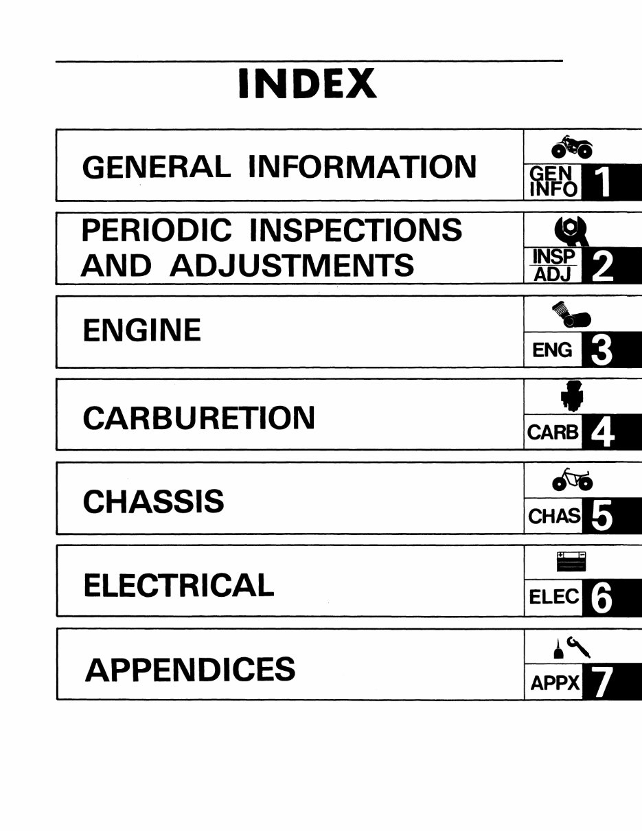
INDEX GENERAL INFORMATION PERIODIC INSPECTIONS AND ADJUSTMENTS ENGINE CARBURETION CHASSIS ELECTRICAL APPENDICES "- ENG ~ CH Iii ELEC ~, APPX
CHAPTER 1. GENERAL INFORMATION MACHINE IDENTIFiCATION .................................... 1-1 VEHICLE IDENTIFICATION NUMBER ......................... 1-1 ENGINE SERIAL NUMBER .................................. 1-1 IMPORTANT INFORMATION .................................... 1-2 ALL REPLACEMENT PARTS .............................. ' ... 1-2 GASKETS, OIL SEALS, AND O-RINGS ........................ 1-2 LOCK WASHERS/PLATES AND COTTER PINS .................. 1-2 BEARINGS AND OIL SEALS ................................ 1-2 CI RCLIPS ................................................. 1-3 SPECIAL TOOLS .............................................. 1-3 FOR TUNE-UP ............................................. 1-3 FOR ENGINE SERViCE ..................................... 1-4 FOR MIDDLE GEAR SERViCE ............................... 1-7 FOR FINAL GEAR SERVICE .................................. 1-8 FOR CHASSIS SERVICE ...................................... 1-8 FOR ELECTRICAL COMPONENTS ............................. 1-9
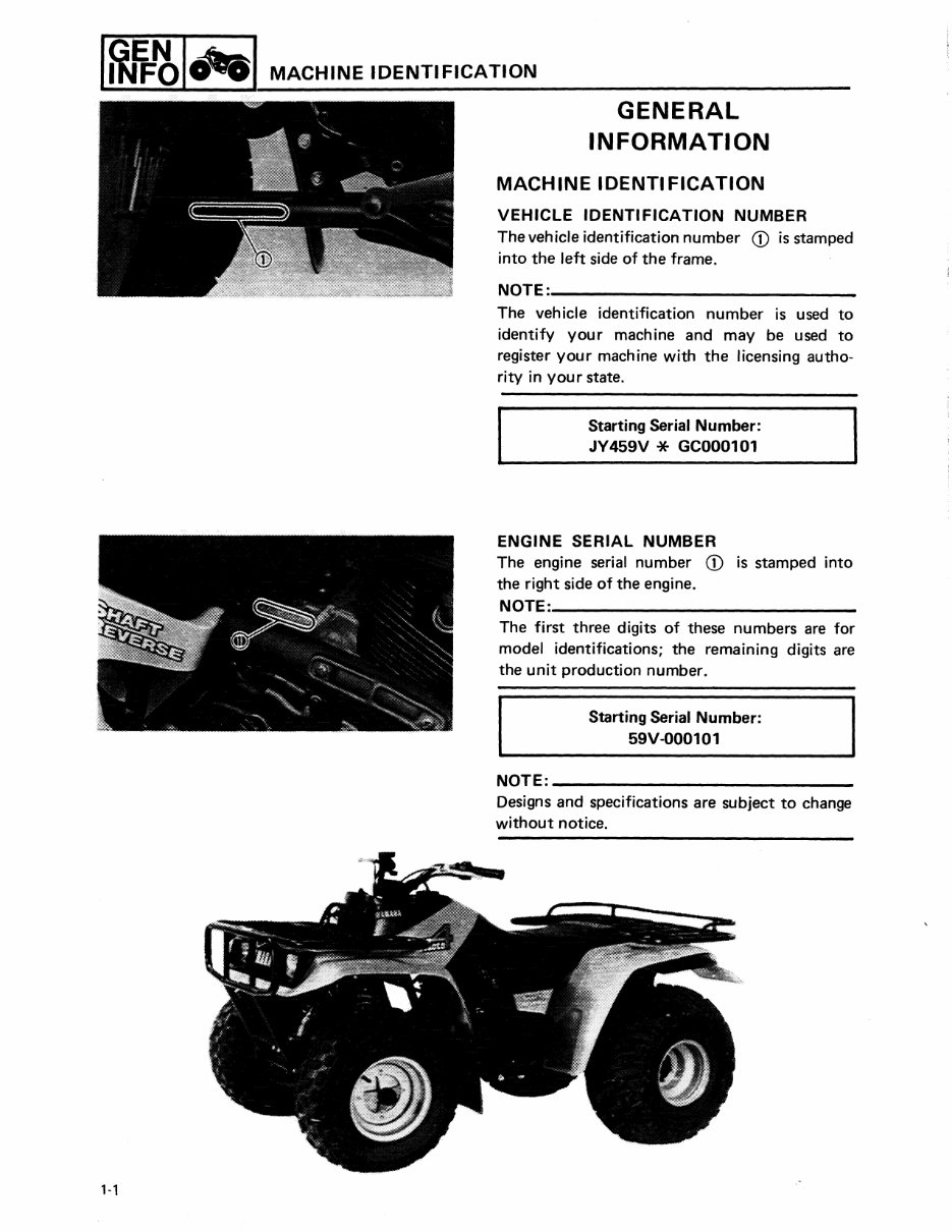
I~l-~I"'I MACHINE IDENTIFICATION 1-1 GENERAL INFORMATION MACHINE IDENTIFICATION VEHICLE IDENTI FICATION NUMBER The vehicle identification number CD is stamped into the left side of the frame. NOTE:; ________________________ ___ The vehicle identification number is used to identify your machine and may be used to register your machine with the licensing autho- rity in your state. Starting Serial Number: JY 459V * GC000101 ENGINE SERIAL NUMBER The engine serial number CD is stamped into the right side of the engine. NOTE:. _______________________ _ The first three digits of these numbers are for model identifications; the remaining digits are the unit production number. Starting Serial Number: 59V-000101 NOTE: ________________________ __ Designs and specifications are subject to change without notice.
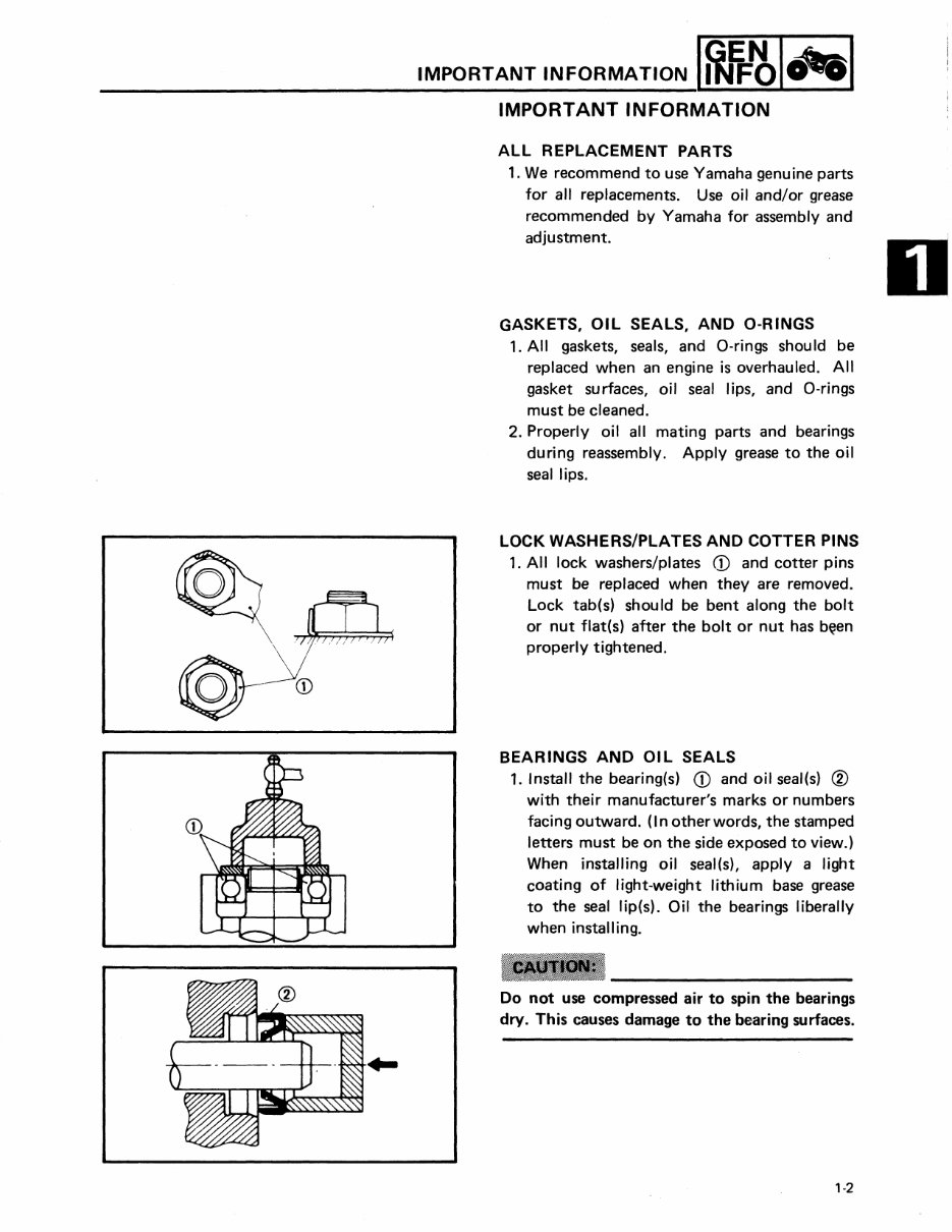
IMPORTANT INFORMATION I~IJ=~I .... I IMPORTANT INFORMATION ALL REPLACEMENT PARTS 1. We recommend to use Yamaha genuine parts for all replacements. Use oil and/or grease recommended by Yamaha for assembly and adjustment. GASKETS, OIL SEALS, AND a-RINGS 1. All gaskets, seals, and O-rings shou Id be replaced when an engine is overhauled. All gasket surfaces, oil seal lips, and O-rings must be cleaned. 2. Properly oil all mating parts and bearings during reassembly. Apply grease to the oil seal lips. LOCK WASHERS/PLATES AND COTTER PINS 1. All lock washers/plates CD and cotter pins must be replaced when they are removed. Lock tab(s) should be bent along the bolt or nut flat(s) after the bolt or nut has b~en properly tightened. BEARINGS AND OIL SEALS 1. Install the bearing(s) CD and oil seal(s) ® with their manufacturer's marks or numbers facing outward. (I n other words, the stamped letters must be on the side exposed to view.) When installing oil seal(s), apply a light coating of light-weight lithium base grease to the seal lip(s). Oil the bearings liberally when installing. Do not use compressed air to spin the bearings dry. This causes damage to the bearing surfaces. 1-2
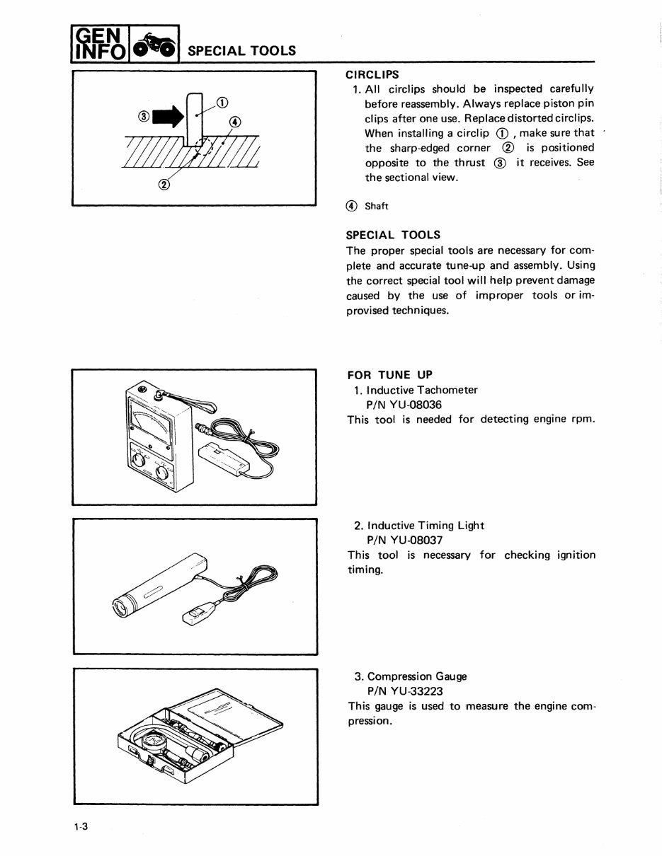
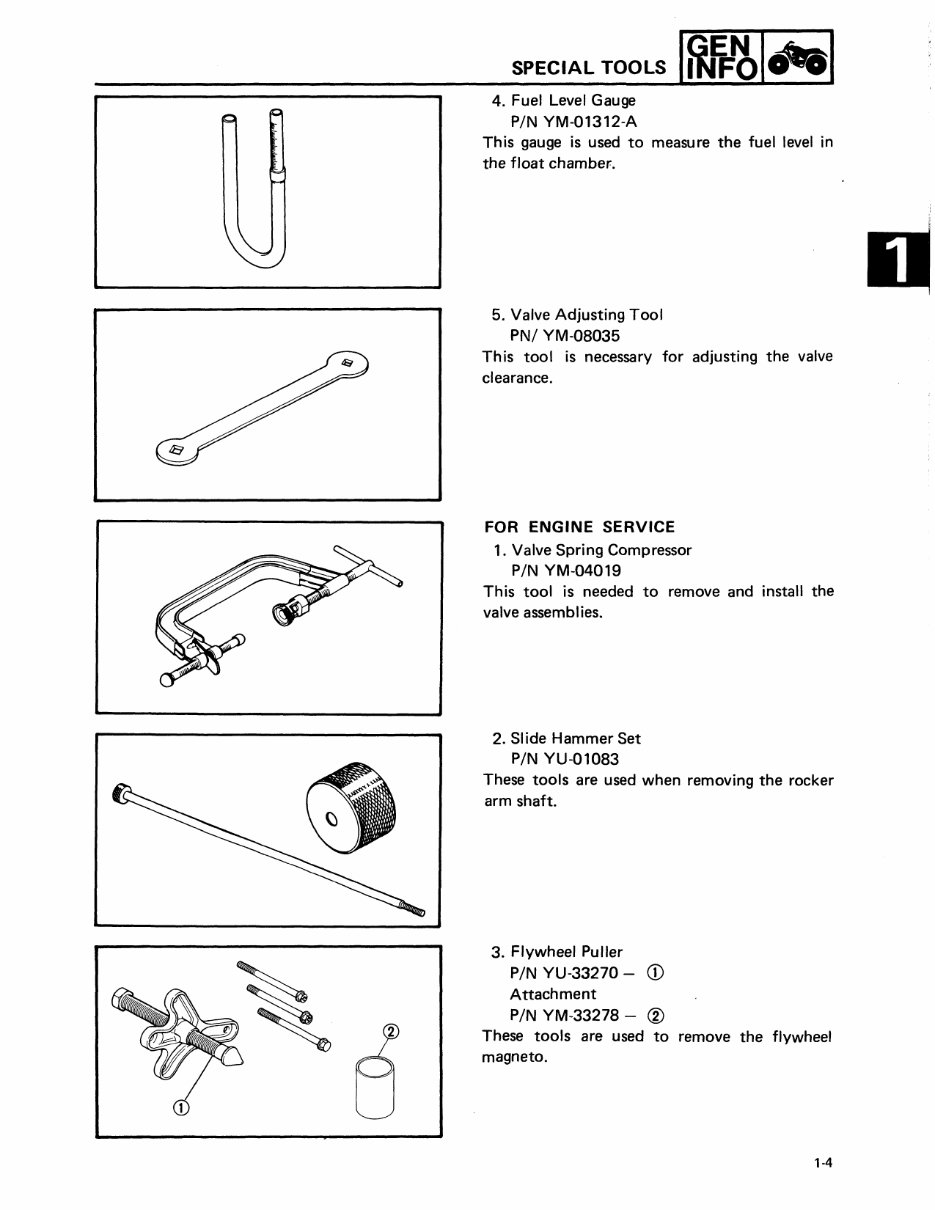
I~EJ=~I'-'I SPECIAL TOOLS 1-3 CIRCLIPS 1. All circlips should be inspected carefully before reassembly. Always replace piston pin clips after one use. Replacedistortedcirclips. When installing a circlip CD , make sure that the sharp-edged corner ® is positioned opposite to the thrust ® it receives. See the sectional view. ® Shaft SPECIAL TOOLS The proper special tools are necessary for com- plete and accurate tune-up and assembly. Using the correct special tool will help prevent damage caused by the use of improper tools or im- provised techniques. FOR TUNE UP 1. Inductive Tachometer PIN YU-08036 This tool is needed for detecting engine rpm. 2. Inductive Timing Light PIN YU-08037 This tool is necessary for checking ignition timing. 3. Compression Gauge PIN YU-33223 This gauge is used to measure the engine com- pression.
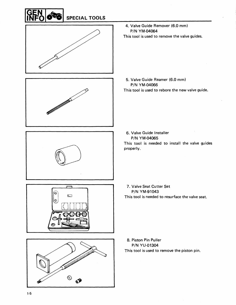
SPECIAL TOOLS 4. Fuel Level Gauge PIN YM-01312-A This gauge is used to measure the fuel level in the float chamber. 5. Valve Adjusting Tool PNI YM-08035 This tool is necessary for adjusting the valve clearance. FOR ENGINE SERVICE 1. Valve Spring Compressor PIN YM-04019 This tool is needed to remove and install the valve assemblies. 2. Slide Hammer Set PIN YU-01083 These tools are used when removing the rocker arm shaft. 3. Flywheel Puller PIN YU-33270 - CD Attachment PIN YM-33278 - @ These tools are used to remove the flywheel magneto. '-4
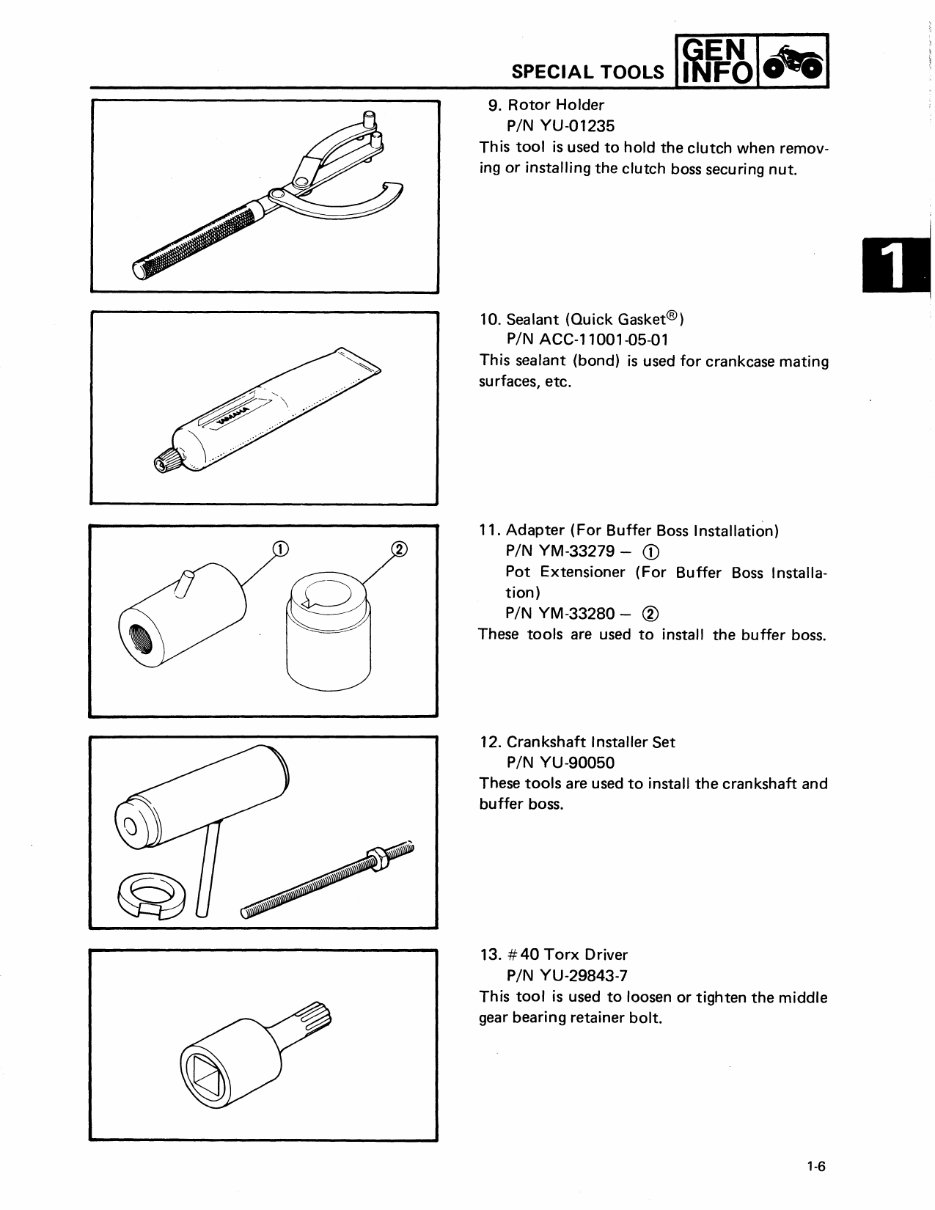
1~1j:.~1""1 SPECIAL TOOLS , ...... , ~ rn7mn /~O@O@ ~~ 1-5 4. Valve Guide Remover (6.0 mm) PIN YM-04064 This tool is used to remove the valve guides. 5. Valve Guide Reamer (6.0 mm) PIN YM-04066 This tool is used to rebore the new valve guide. 6. Valve Guide Installer PIN YM-04065 This tool is needed to install the valve guides properly. 7. Valve Seat Cutter Set PIN YM-91043 This tool is needed to resurface the valve seat. 8. Piston Pin Puller PIN YU-Q1304 This tool is used to remove the piston pin.
SPECIAL TOOLS I~IJ=~I"I 9. Rotor Holder PIN YU-01235 This tool is used to hold the clutch when remov- ing or installing the clutch boss securing nut. 10. Sealant (Quick Gasket®) PIN ACC-ll00l-05-01 This sealant (bond) is used for crankcase mating surfaces, etc. 11. Adapter (For Buffer Boss Installation) 2 PIN YM-33279 - CD Pot Extensioner (For Buffer Boss I nstalla- tion) PIN YM-33280 - ® These tools are used to install the buffer boss. 12. Crankshaft Installer Set PIN YU-90050 These tools are used to install the crankshaft and buffer boss. 13. #40 Torx Driver PIN YU-29843-7 This tool is used to loosen or tighten the middle gear bearing retainer bolt. '·6
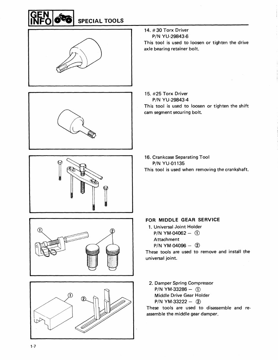
1~1j:~1"'1 SPECIAL TOOLS 1·7 14. #30 Torx Driver PIN YU-29843-6 This tool is used to loosen or tighten the drive axle bearing retainer bolt. 15. #25 Torx Driver PIN YU-29843-4 This tool is used .to loosen or tighten the shift cam segment securing bolt. 16. Crankcase Separating Tool PIN YU-01135 This tool is used when removing the crankshaft. FOR MIDDLE GEAR SERVICE 1. Universal Joint Holder PIN YM-04062 - CD Attachment PIN YM-04096 - @ These tools are used to remove and install the universal joint. 2. Damper Spring Compressor PIN YM-33286 - CD Middle Drive Gear Holder PIN YM-33222 - @ These tools are used to disassemble and re- assemble the middle gear damper.
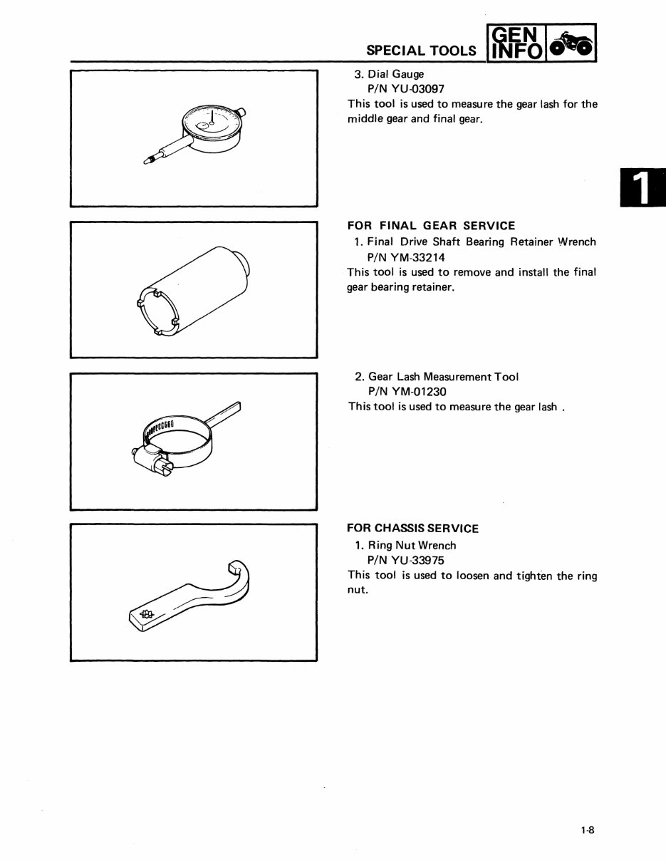
SPECIAL TOOLS 3. Dial Gauge PIN YU-03097 This tool is used to measure the gear lash for the middle gear and final gear. FOR FINAL GEAR SERVICE 1. Final Drive Shaft Bearing Retainer Wrench PIN YM-33214 This tool is used to remove and install the final gear bearing retainer. 2. Gear Lash Measurement Tool PIN YM-01230 This tool is used to measure the gear lash. FOR CHASSIS SERVICE 1. Ring Nut Wrench PIN YU-33975 This tool is used to loosen and tighten the ring nut. 1·8
Get the improved repair manual for the 1986-1988 Yamaha Moto 4 225 ATV. This service manual is essential for professional mechanics and DIY enthusiasts alike. It includes bookmarks, searchable text, and an index for the best organization.
It covers general information, periodic inspections and adjustments, engine overhaul, carburetion, chassis, electrical, appendices, and wiring diagrams. The manual is in PDF format, consists of 249 pages, and is printable without any restrictions. It requires Adobe Reader for access.
Investing in the right repair manual for your motorcycle will save you money and provide in-depth knowledge. By choosing instant download, you can save on repair and maintenance costs without waiting for shipping. Take advantage of this manual to complete all your repairs today and get full value for your money.
General Information
Periodic Inspections And Adjustments
Engine Overhaul
Carburetion
Chassis
Electrical
Appendices
Wiring Diagram
Customer satisfaction is guaranteed. Don't hesitate, get this manual now and empower yourself with the knowledge to maintain and repair your motorcycle.

")