EB001000 NOTICE This manual was produced by the Yamaha Motor Company primarily for use by Yamaha dealers and their qualified mechanics. It is not possible to include all the knowledge of a mechanic in one manual, so it is assumed that anyone who uses this book to perform main- tenance and repairs on Yamaha machine has a basic understanding of the mechanical ideas and the procedures of machine repair. Repairs attempted by anyone without this knowledge are likely to render the machine unsafe and unfit for use. Yamaha Motor Company, Ltd. is continually striving to improve all its models. Modifications and significant changes in. specifications or procedures will be forwarded to all authorized Yamaha dealers and will appear in future editions of this manual where applicable. NOTE: ______________________________________________________ ___ Designs and specifications are subject to change without notice. IMPORTANT INFORMATION Particularly important information is distinguished in this manual by the following notations. A WARNING NOTE: The Safety Alert Symbol means ATTENTION! BECOME ALERT! YOUR SAFETY IS INVOLVED! Failure to follow WARNING instructions could result in severe injury or death to the machine operator, a bystander or a person inspecting or repairing the machine. A CAUTION indicates special precautions that must be taken to avoid damage to the machine. A NOTE provides key information to make procedures easier or clearer.
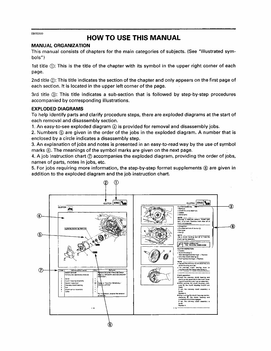
EB002000 HOW TO USE THIS MANUAL MANUAL ORGANIZATION This manual consists of chapters for the main categories of subjects. (See "illustrated sym- bols") 1st title CD: This is the title of the chapter with its symbol in the upper right corner of each page. 2nd title ®: This title indicates the section of the chapter and only appears on the first page of each section. It is located in the upper left corner of the page. 3rd title @: This title indicates a sub-section that is followed by step-by-step procedures accompanied by corresponding illustrations. EXPLODED DIAGRAMS To help identify parts and clarify procedure steps, there are exploded diagrams at the start of each removal and disassembly section. 1. An easy-to-see exploded diagram @ is provided for removal and disassembly jobs. 2. Numbers ® are given in the order of the jobs in the exploded diagram. A number that is enclosed by a circle indicates a disassembly step. 3. An explanation of jobs and notes is presented in an easy-to-read way by the use of symbol marks @. The meanings of the symbol marks are given on the next page. . 4. A job instruction chart (j) accompanies the exploded diagram, providing the order of jobs, names of parts, notes in jobs, etc. 5. For jobs requiring more information, the step-by-step format supplements @ are given in addition to the exploded diagram and the job instruction chart. CLUTCH ~ A / /1 1-:; 1 Pr,maryandsecond3ryshellyes CLUTCH CLUTCH REMOVAl 'Remove: • Clu!chhousong,S&embly .G.Pet • Qowelpms :'~~Il~~·"7i"-=C;$5(:='~-' ,.= ... -'-,.,. J'-~M-" • ...,,- .. , bolt 1/. of lurn. Remove them .fter att 01 2.Straighten • Punched porttonof Ihenul(i) 3.Remove: eNut(D ~~T~: c=lutC:C-::"=Oldin=, '=~'-;;;-(j) ,::-":, ,=".=", clutchcarrie,assem\)ly ~Clutc:hhcUdlngt~: I ~ P/N.YM-"042,90890-04086 . CLUTCH INSPECTION lln~ec:t· • Clutch housil'lg(D He&tdamage/wearJdamage ..... Replace . • One-way clutCh bearing(i) Chafong/we,rfdamage ... Replace ~~:~~="'=""="='''=Iutch= .. = .. m=blya=". clutch housing asa sel. .The one-way Clutch bearing must be installe<!w'th the ftanges!delacino in Clutchopef.tlon: .In$l.lt the one·way clutch bearing .ntl cluo::thcaHierassemblytothaclucthhous· ,ng and hold Iheclutch carner assembly . • When tum,ng the Clutch hOUSIng clock· w,se @. the Clutch housing should tum trealy II not, the one-way clutch assembly,s laulty Replace,!. .When lurn,ng the clutCh housing counter· clockwiH' !Il. the clutch houSIng and crank$halt Should beengllged II not, the one,wllY Clutch assembly,s faullY Repllce,!
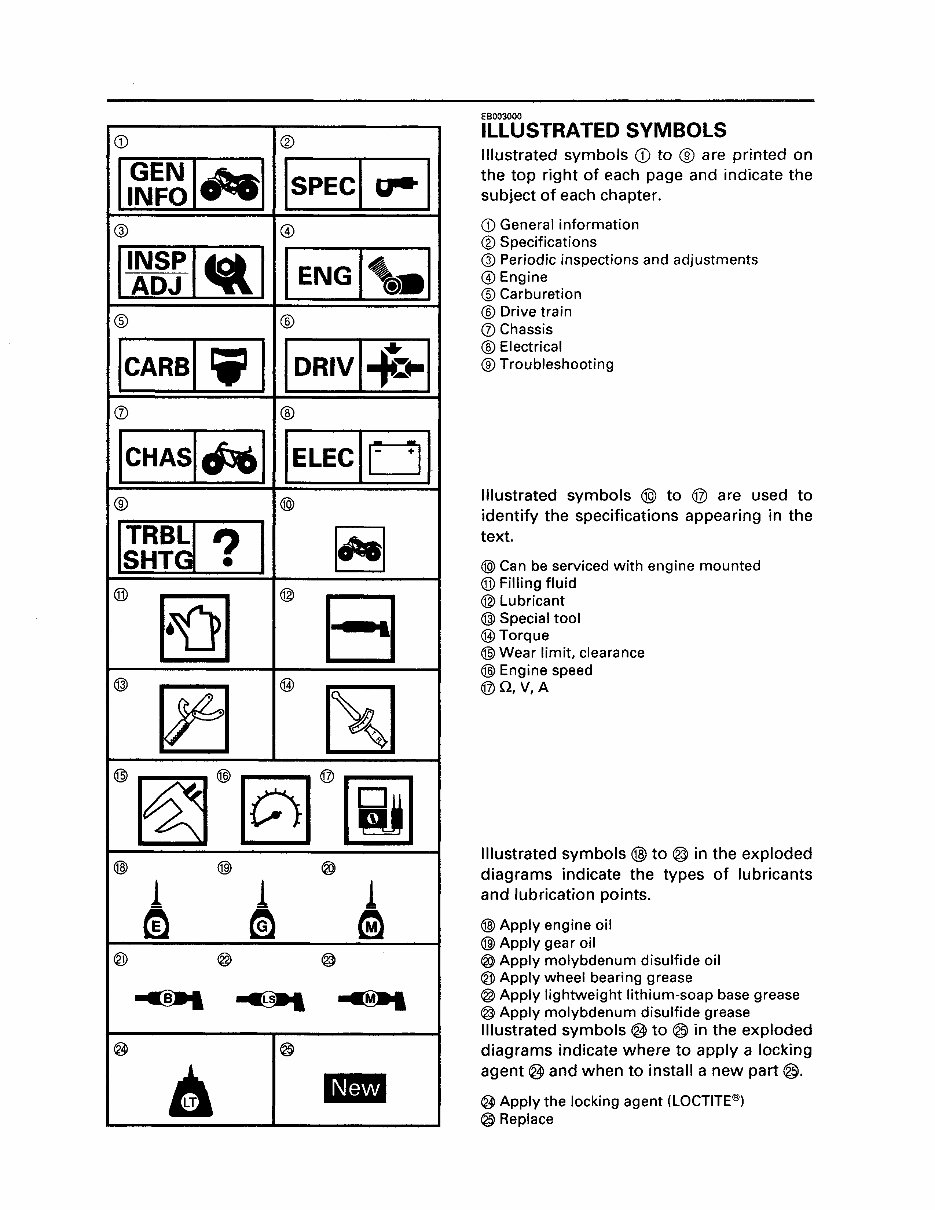
CD ® 11~~~14te1 ISPECI ~ I @ @ II:gs 14fil1 ENG <I '®. ® ® ICARBI Ii' I IDRIVI*~1 (j) ® ICHASldsOl IELECIOI ® @ IJ~~~ ? I ~ ® ro1 @ El @ ~ @) ~ @~@§@~ @) @) ® 1 1 1 m ~ Gl ® @ @ ~ ..... ~ @ ® A ~ EB003000 ILLUSTRATED SYMBOLS Illustrated symbols CD to ® are printed on the top right of each page and indicate the subject of each chapter. CD General information ® Specifications @ Periodic inspections and adjustments @Engine ® Carburetion ® Drive train (j) Chassis ® Electrical ® Troubleshooting Illustrated symbols ® to ® are used to identify the specifications appearing in the text. @ Can be serviced with engine mounted ® Filling fluid @ Lubricant @ Special tool @)Torque @ Wear limit, clearance @) Engine speed @Q,V,A Illustrated symbols (j]) to ® in the exploded diagrams indicate the types of lubricants and lubrication points. @) Apply engine oil @) Apply gear oil ® Apply molybdenum disulfide oil ® Apply wheel bearing grease @ Apply lightweight lithium-soap base grease @ Apply molybdenum disulfide grease Illustrated symbols ~ to @ in the exploded diagrams indicate where to apply a locking agent ® and when to install a new part @. @ Apply the locking agent (LOCTITE@) ® Replace
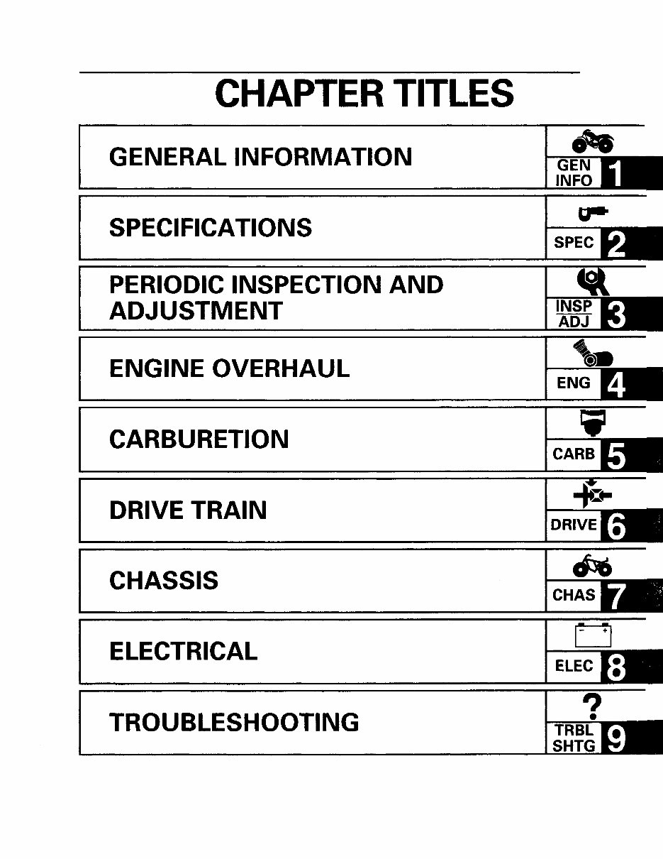
CHAPTER TITLES GENERAL INFORMATION SPECIFICATIONS PERIODIC INSPECTION AND ADJUSTMENT ENGINE OVERHAUL CARBURETION DRIVE TRAIN CHASSIS ELECTRICAL TROUBLESHOOTING CHAS o ELEC ?
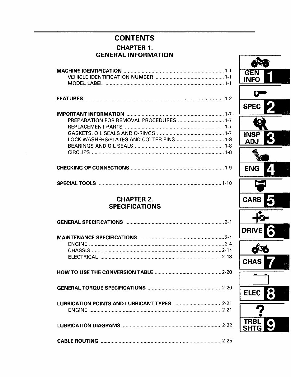
CONTENTS CHAPTER 1. GENERAL INFORMATION MACHINE IDENTIFICATION ........................................................................ 1-1 VEHICLE IDENTIFICATION NUMBER ................................................. 1-1 MODEL LABEL ..................................................................................... 1-1 FEATURES .................................................................................................... 1-2 IMPORTANT INFORMATION ...................................................................... 1-7 PREPARATION FOR REMOVAL PROCEDURES ................................. 1-7 REPLACEMENT PARTS ....................................................................... 1-7 GASKETS, OIL SEALS AND O-RINGS ................................................ 1-7 LOCK WASHERS/PLATES AND COTTER PINS .................................. 1-8 BEARINGS AND OIL SEALS ................................................................ 1-8 CIRCLIPS ............................................................................................... 1-8 CHECKING OF CONNECTIONS ................................................................... 1-9 SPECIAL TOOLS ........................................................................................ 1-10 CHAPTER 2. SPECIFICATIONS GENERAL SPECIFICATIONS ....................................................................... 2-1 MAINTENANCE SPECIFICATIONS ............................................................. 2-4 ENGINE ................................................................................................. 2-4 CHASSIS ............................................................................................. 2-14 ELECTRICAL ....................................................................................... 2-18 HOW TO USE THE CONVERSION TABLE ................................................ 2-20 GENERAL TORQUE SPECIFICATIONS ..................................................... 2-20 LUBRICATION POINTS AND LUBRICANT TYPES ................................... 2-21 ENGINE ............................................................................................... 2-21 LUBRICATION DIAGRAMS ....................................................................... 2-22 CABLE ROUTING ....................................................................................... 2-25 CHAS o ELEC
CHAPTER 3. PERIODIC INSPECTIONS AND ADJUSTMENTS INTRODUCTION ........................................................................................... 3-1 PERIODIC MAINTENANCE/LUBRICATION INTERVALS ........................... 3-1 SEAT, CARRIERS, FENDERS AND FUEL TANK ......................................... 3-3 SEAT ..................................................................................................... 3-3 FRONT CARRIER, FRONT BUMPER AND FRONT FENDER .............. 3-4 REAR CARRIER AND REAR FENDER .................................................. 3-5 FUEL TANK ........................................................................................... 3-6 ENGINE ......................................................................................................... 3-7 VALVE CLEARANCE ADJUSTMENT .................................................. 3-7 TIMING CHAIN ADJUSTMENT ......................................................... 3-10 IDLING SPEED ADJUSTMENT .......................................................... 3-10 THROTILE LEVER FREE PLAY ADJUSTMENT ................................ 3-11 SPEED LIMITER ADJUSTMENT ........................................................ 3-13 SPARK PLUG INSPECTION .................................................... :.......... 3-14 IGNITION TIMING CHECK ................................................................. 3-15 COMPRESSION PRESSURE MEASUREMENT ................................ 3-16 ENGINE OIL LEVEL INSPECTION ..................................................... 3-17 OIL TEMP WARNING LIGHT CHECK ................................................ 3-18 ENGINE OIL REPLACEMENT ............................................................ 3-19 AIR FILTER CLEANING ...................................................................... 3-20· V-BELT INSPECTION ......................................................................... 3-22 CHASSIS ..................................................................................................... 3-24 FRONT BRAKE ADJUSTMENT ......................................................... 3-24 REAR BRAKE LEVER AND PEDAL ADJUSTMENT .......................... 3-24 FRONT BRAKE FLUID LEVEL INSPECTION ..................................... 3-26 FRONT BRAKE PAD INSPECTION .................................................... 3-27 REAR BRAKE SHOE INSPECTION .................................................... 3-27 BRAKE HOSE INSPECTION ............................................................... 3-28 AIR BLEEDING (HYDRAULIC BRAKE SYSTEM) .............................. 3-28 SELECT LEVER CONTROL CABLE AND SHIFT ROD ADJUSTMENT ................................................................................ 3-30 FINAL GEAR OIL LEVEL INSPECTION .............................................. 3-31 FINAL GEAR REPLACEMENT ............................................................ 3-31 DIFFERENTIAL GEAR OIL REPLACEMENT ...................................... 3-32 CONSTANT VELOCITY JOINT DUST BOOT INSPECTION ............. 3-33 STEERING SYSTEM INSPECTION .................................................... 3-33 TOE-IN ADJUSTMENT ...................................................................... 3-34 REAR SHOCK ABSORBER ADJUSTMENT ....................................... 3-36 TIRE INSPECTION .............................................................................. 3-36 WHEEL INSPECTION ......................................................................... 3-38 CABLE INSPECTION AND LUBRICATION ........................................ 3-39 LEVERS, PEDAL, ETC. LUBRICATION .............................................. 3-39
ELECTRICAL ............................................................................................... 3-40 BATTERY INSPECTION ..................................................................... 3-40 FUSE INSPECTION ............................................................................ 3-45 HEADLIGHT BEAM ADJUSTMENT .................................................. 3-47 HEADLIGHT BULB REPLACEMENT .................................................. 3-47 CHAPTER 4. ENGINE ENGINE REMOVAL ...................................................................................... 4-1 AIR DUCTS, MUFFLER, EXHAUST PIPE, AND FOOTLEST BOARD (right) .................................................................................... 4-1 SELECT LEVER UNIT AND FOOTREST BOARD (left) ......................... 4-2 HOSES AND LEADS ............................................................................ 4-3 ENGINE MOUNTING BOLTS .............................................................. 4-4 CYLINDER HEAD COVER ............................................................................ 4-6 CYLINDER HEAD COVER REMOVAL .................................................. 4-7 CYLINDER HEAD COVER INSPECTION .............................................. 4-7 TAPPET COVER INSPECTION ............................................................. 4-7 CYLINDER HEAD COVER INSTALLATION ......................................... 4-8 ROCKER ARMS ............................................................................................ 4-9 ROCKER ARM REMOVAL .................................................................. 4-10 ROCKER ARM AND CAMSHAFT INSPECTION ................................ 4-10 ROCKER ARM INSTALLATION ......................................................... 4-11 CAMSHAFT AND CYLINDER HEAD .......................................................... 4-12 CAMSHAFT AND CYLINDER HEAD REMOVAL .............................. .4-14 CAMSHAFT INSPECTION .................................................................. 4-15 CAMSHAFT SPROCKET INSPECTION .............................................. 4-15 DECOMPRESSION SYSTEM INSPECTION ...................................... 4-15 TIMING CHAIN GUIDE INSPECTION ................................................ 4-16 TIMING CHAIN TENTIONER INSPECTION ....................................... 4-16 CYLINDER HEAD INSPECTION ......................................................... 4-16 CAMSHAFT AND CYLINDER HEAD INSTALLATION ..................... .4-17 VALVES AND VALVE SPRINGS ............................................................... 4-20 VALVE AND VALVE SPRING REMOVAL .......................................... 4-21 VALVE AND VALVE SPRING INSPECTION ...................................... 4-21 VALVE AND VALVE SPRING INSTALLATION ................................. 4-26 CYLINDER AND PISTON ........................................................................... 4-27 PISTON REMOVAL ............................................................................ 4-28 CYLINDER AND PISTON INSPECTION ............................................. 4-28 PISTON RING INSPECTION .............................................................. 4-30 PISTON PIN INSPECTION ................................................................. 4-31 CHAS o ELEC ? • TRBL SHTG
This workshop service manual is designed for the 1998-2001 Yamaha Grizzly 600 (YFM600/YFM600FWAK) ATV OEM Service & Repair Manual. It is intended for professional mechanics and DIY enthusiasts who are familiar with general automobile practices.
The manual covers repair and overhaul procedures specific to the Yamaha Grizzly 600 models from 1998 to 2001, including detailed instructions on components manufactured for these models. It incorporates manufacturer guidelines to ensure technicians understand component functions and evaluate overall vehicle performance.
The content provides reliable information, with important details underscored by the symbols and wording: WARNING, CAUTION, NOTE. It offers diagnostic and repair procedures for routine maintenance and servicing, enabling users to perform many simpler tasks themselves and save on expenses.
For those planning maintenance and repair on their Yamaha Grizzly 600, the manual advises the use of proper safety equipment and precautions. It also identifies and illustrates any special tools recommended or required for adjustments or repairs.
Owning and referring to this manual will empower Yamaha Grizzly 600 owners to undertake repairs with professional-level expertise. The manual includes all essential instructions needed for any repair the vehicle may require.
The guide includes specifications and procedures that are available in an authorized Yamaha dealer service department, covering tune-ups, maintenance, removal & installation procedures, assemblies & disassemblies, fuel system, ignition, lubrication system, exhaust, electrical system, body, and more extensive repairs involving engine and transmission disassembly.
This is delivered electronically via email in English as a .PDF file. The content depicts parts and procedures applicable to the product as of the time of writing.
General Information
Maintenance
Lubrication
Heating
Ventilation
Air Conditioning
Suspension
Front Suspension
Rear Suspension
Wheel
Tire System
Differential
Driveline
Drive Shaft
Transfer Case
Brakes
Engine
Engine Mechanical
Engine Cooling
Engine Fuel
Engine Electrical
Ignition System
Starting
Charging System
Emissions
Engine Exhaust
Engine Lubrication
Engine Speed Control System
Clutch
Cooling
Electronic Control Modules
Engine Systems
Heated Systems
Horn
Ignition Control
Instrument Cluster
Lamps
Power Systems
Restraints
Speed Control
Transmission
Exhaust System
Body Structure
Seats
Security and Locks
Air Bag System
Exterior Trim
Interior Trim
Frame
Bumpers
Fuel System
Steering
Transmission and Transfer Case
Tires
Wheels
Body
Heating
Air Conditioning
Emissions Control
Engine Removal
Engine Installation
Final Drive
Electrical System
Air cleaner element renewal
Air cleaner temperature control check
Auxiliary drivebelt check
Battery electrolyte level check
Battery terminal check
Brake hydraulic fluid renewal
Brake hydraulic system seal and hose renewal
Brake pipe and hose check
Choke adjustment check
Contact breaker point renewal and distributor lubrication