

2000-2006 Yamaha Big Bear 400 ATV Service & Repair Manual
What's Included?
Fast Download Speeds
Online & Offline Access
Access PDF Contents & Bookmarks
Full Search Facility
Print one or all pages of your manual

YFM400FWNP
SUPPLEMENTARY
SERVICE MANUAL
LIT-11616-15-22 5FU-F8197-E1

FOREWORD
This Supplementary Service Manual has been prepared to introduce new service and new data for
the YFM400FWNP. For complete information on service procedures, it is necessary to use this Sup-
plementary Service Manual together with the following manual.
YFM400FWNM/YFM400FWNMC SERVICE MANUAL: LIT-11616-13-22 (5FU-F8197-E0)
YFM400FWNP
SUPPLEMENTARY
SERVICE MANUAL
2001 by Yamaha Motor Corporation, U.S.A.
First Edition, June 2001
All rights reserved.
Any reproduction or unauthorized use
without the written permission of
Yamaha Motor Corporation, U.S.A.
is expressly prohibited.
Printed in U.S.A.
LIT-11616-15-22

EB001000
NOTICE
This manual was produced by the Yamaha Motor Company primarily for use by Yamaha dealers
and their qualified mechanics. It is not possible to include all the knowledge of a mechanic in one
manual, so it is assumed that anyone who uses this book to perform maintenance and repairs on
Yamaha machine has a basic understanding of the mechanical ideas and the procedures of
machine repair. Repairs attempted by anyone without this knowledge are likely to render the
machine unsafe and unfit for use.
Yamaha Motor Company, Ltd. is continually striving to improve all its models. Modifications and sig-
nificant changes in specifications or procedures will be forwarded to all authorized Yamaha dealers
and will appear in future editions of this manual where applicable.
NOTE:
Designs and specifications are subject to change without notice.
IMPORTANT INFORMATION
Particularly important information is distinguished in this manual by the following notations.
The Safety Alert Symbol means ATTENTION! BECOME ALERT! YOUR
SAFETY IS INVOLVED!
Failure to follow WARNING instructions could result in severe injury or death
to the machine operator, a bystander or a person inspecting or repairing the
machine.
A CAUTION indicates special precautions that must be taken to avoid dam-
age to the machine.
A NOTE provides key information to make procedures easier or clearer.
WARNING
CAUTION:
NOTE:
HOW TO USE THIS MANUAL
CONSTRUCTION OF THIS MANUAL
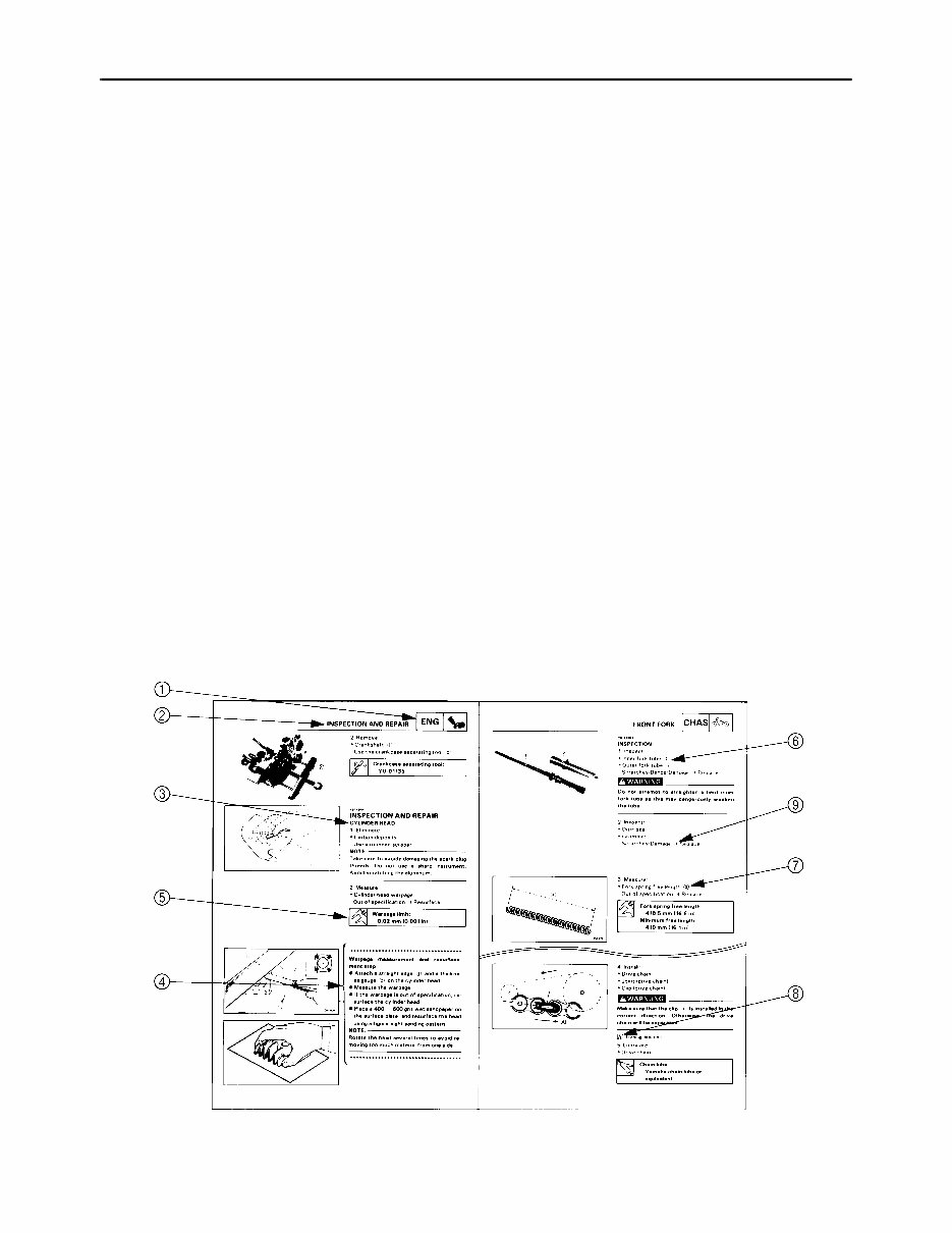
This manual consists of chapters for the main categories of subjects. (See “Illustrated symbols”)
1st title 1: This is a chapter with its symbol on the upper right of each page.
2nd title 2: This title appears on the upper of each page on the left of the chapter sym-
bol. (For the chapter “Periodic inspection and adjustment” the 3rd title
appears.)
3rd title 3: This is a final title.
MANUAL FORMAT
All of the procedures in this manual are organized in a sequential, step-by-step format. The informa-
tion has been compiled to provide the mechanic with an easy to read, handy reference that contains
comprehensive explanations of all disassembly, repair, assembly, and inspections.
A set of particularly important procedure 4 is placed between a line of asterisks “*” with each proce-
dure preceded by “●”.
IMPORTANT FEATURES
● Data and a special tool are framed in a box preceded by a relevant symbol 5.
● An encircled numeral 6 indicates a part name, and an encircled alphabetical letter data or an
alignment mark 7, the others being indicated by an alphabetical letter in a box 8.
● A condition of a faulty component will precede an arrow symbol 9 and the course of action will fol-
low it.
EXPLODED DIAGRAM
Each chapter provides exploded diagrams before each disassembly section for ease in identifying
correct disassembly and assembly procedures.
EB003000
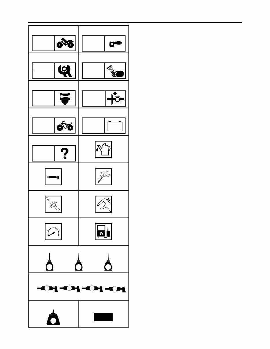
ILLUSTRATED SYMBOLS
Illustrated symbols 1 to 9 are printed on the
top right of each page and indicate the subject
of each chapter.
1 General information
2 Specifications
3 Periodic checks and adjustments
4 Engine
5 Carburetion
6 Drive train
7 Chassis
8 Electrical
9 Troubleshooting
Illustrated symbols 0 to F are used to identify
the specifications appearing in the text.
0 Filling fluid
A Lubricant
B Special tool
C Torque
D Wear limit, clearance
E Engine speed
F Ω, V, A
Illustrated symbols G to M in the exploded
diagrams indicate the types of lubricants and
lubrication points.
G Apply engine oil
H Apply gear oil
I Apply molybdenum disulfide oil
J Apply wheel bearing grease
K Apply lightweight lithium soap base grease
L Apply molybdenum disulfide grease
M Apply silicon grease
Illustrated symbols N to O in the exploded
diagrams indicate where to apply a locking
agent N and when to install a new part O.
N Apply the locking agent (LOCTITE
)
O Replace
1 2
3 4
5 6
7 8
9 0
A B
C D
E F
G H I
J
N O
GEN
INFO
SPEC
CHK
ADJ
ENG
CARB DRIV
CHAS
– +
ELEC
TRBL
SHTG
T
R
.
.
E G M
B LS M
S
K L M
LT
New

CONTENTS
SPECIFICATIONS ........................................................................................... 1
GENERAL SPECIFICATIONS ................................................................. 1
MAINTENANCE SPECIFICATIONS ........................................................ 2
ENGINE................................................................................................ 2
CHASSIS.............................................................................................. 3
ELECTRICAL ....................................................................................... 4
CABLE ROUTING .................................................................................... 5
PERIODIC CHECKS AND ADJUSTMENTS ................................................. 16
INTRODUCTION .................................................................................... 16
PERIODIC MAINTENANCE/LUBRICATION INTERVALS ..................... 16
CHASSIS ................................................................................................ 18
ADJUSTING THE FRONT BRAKE .................................................... 18
ADJUSTING THE REAR BRAKE LIGHT SWITCH ............................ 18
DRIVE TRAIN ................................................................................................. 19
CONSTANT VELOCITY JOINTS AND DIFFERENTIAL GEAR ............. 19
ASSEMBLING THE DIFFERENTIAL GEAR ...................................... 21
MEASURING AND ADJUSTING
THE DIFFERENTIAL GEAR LASH .................................................... 22
ELECTRICAL ................................................................................................. 24
CHECKING THE SWITCH ..................................................................... 24
CHECKING THE SWITCH ................................................................. 24
CHECKING A SWITCH SHOWN IN THE MANUAL .......................... 24
IGNITION SYSTEM ................................................................................ 25
CIRCUIT DIAGRAM ........................................................................... 25
TROUBLESHOOTING ....................................................................... 26
ELECTRIC STARTING SYSTEM ........................................................... 31
CIRCUIT DIAGRAM ........................................................................... 31
TROUBLESHOOTING ....................................................................... 32
LIGHTING SYSTEM ............................................................................... 35
CIRCUIT DIAGRAM ........................................................................... 35
CHECKING THE LIGHTING SYSTEM .............................................. 36
SIGNAL SYSTEM ................................................................................... 37
CIRCUIT DIAGRAM ........................................................................... 37
TROUBLESHOOTING ....................................................................... 38
CHECKING THE SIGNAL SYSTEM .................................................. 40
2WD/4WD SELECTING SYSTEM ......................................................... 42
CIRCUIT DIAGRAM ........................................................................... 42
TROUBLESHOOTING ....................................................................... 43
YFM400FWNP WIRING DIAGRAM
– 1 –
SPEC
GENERAL SPECIFICATIONS
SPECIFICATIONS
GENERAL SPECIFICATIONS
Model YFM400FWNP
Model code: 5FUA (USA)
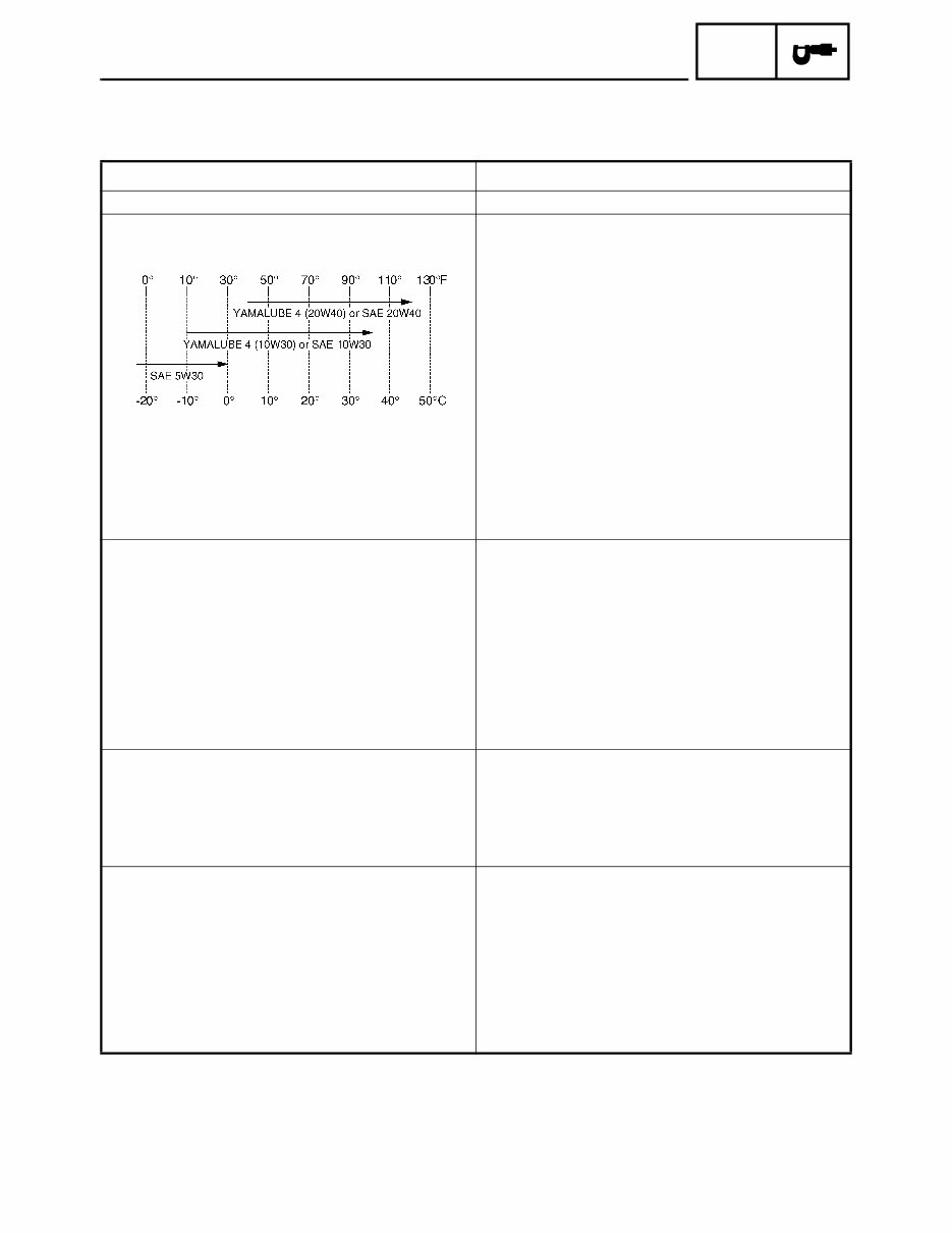
Oil type or grade:
Engine oil
API service SE, SF, SG type or higher
Final gear oil SAE 80 API “GL-4” Hypoid gear oil
Differential gear oil SAE 80 API “GL-4” Hypoid gear oil
Differential gear case oil
Periodic oil change 0.35 L (0.31 Imp qt, 0.37 US qt)
Total amount 0.4 L (0.35 Imp qt, 0.42 US qt)
Chassis:
Frame type Steel tube frame
Caster angle 4°
Camber angle 1°
Kingpin angle 13°
Trail 21 mm (0.83 in)
Tread (STD) front 860 mm (33.86 in)
Tread (STD) rear 820 mm (32.28 in)
Toe-in 5 ~ 15 mm (0.20 ~ 0.59 in)
Brake:
Front brake type Dual disc brake
operation Right hand operation
Rear brake type Drum brake
operation Left hand and right foot operation
Bulb wattage × quantity:
Headlight 12 V 30 W/30 W × 2
Tail/brake light 12 V 5 W/21 W × 1
Meter light 12 V 3.4 W × 1
Neutral indicator light 12 V 1.7 W × 1
Reverse indicator light 12 V 1.7 W × 1
Oil temperature warning light 12 V 1.7 W × 1
Four-wheel drive indicator light 12 V 1.7 W × 1
– 2 –
SPEC
MAINTENANCE SPECIFICATIONS
MAINTENANCE SPECIFICATIONS
ENGINE
Model YFM400FWNP
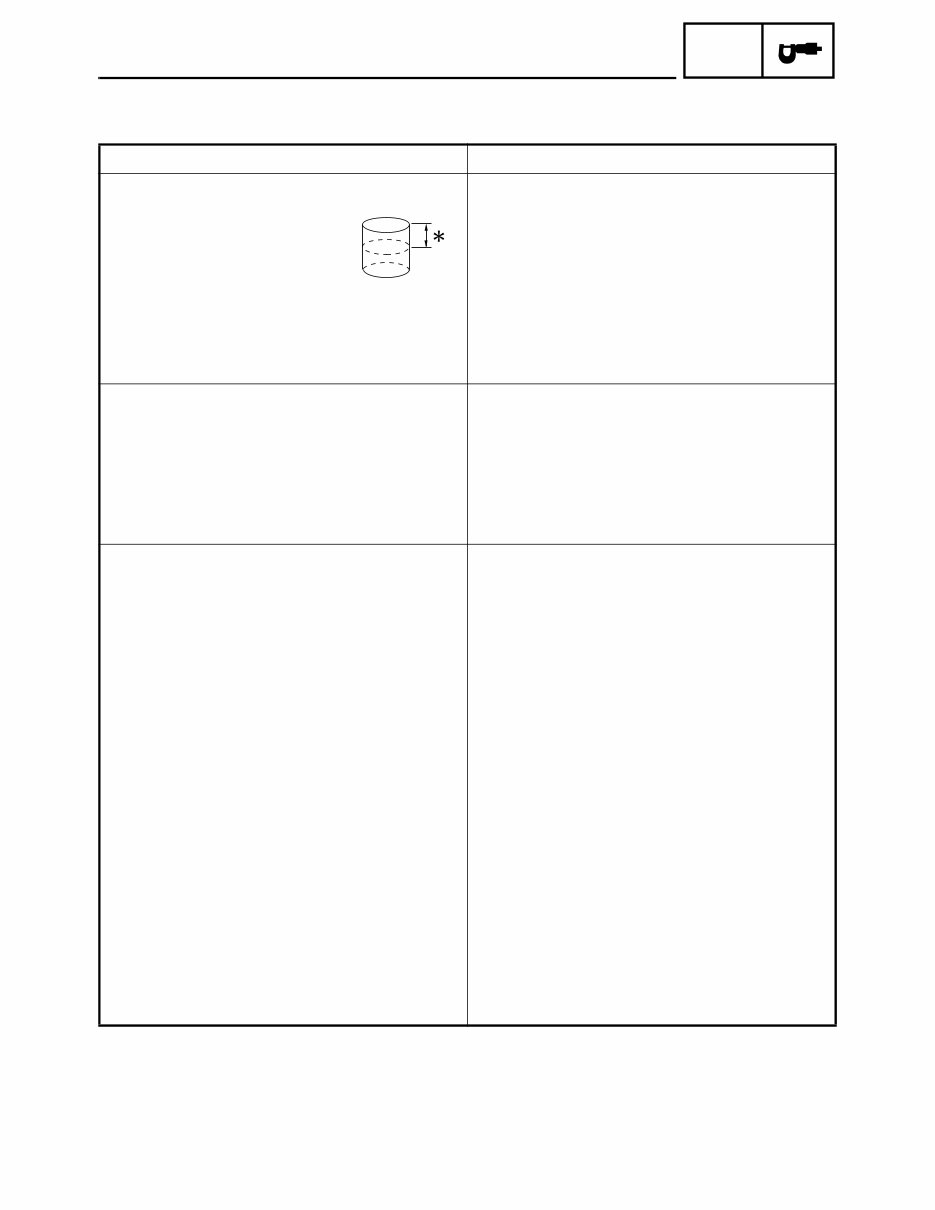
Cylinder:
Bore size 82.97 ~ 83.02 mm (3.267 ~ 3.269 in)
Out of round limit 0.05 mm (0.0020 in)
*
Measuring point 40 mm (1.57 in)
<Wear limit> <83.15 mm (3.274 in)>
Rocker arm/rocker arm shaft:
Bearing inside diameter 11.980 ~ 11.998 mm (0.4717 ~ 0.4724 in)
<Limit> <12.058 mm (0.4747 in)>
Shaft outside diameter 11.961 ~ 11.971 mm (0.4709 ~ 0.4713 in)
<Limit> <11.931 mm (0.4697 in)>
Arm-to-shaft clearance 0.009 ~ 0.037 mm (0.0004 ~ 0.0015 in)
<Limit> <0.08 mm (0.0031 in)>
Carburetor:
I. D. mark 5FUA 12
Main jet (M.J.) #112.5
Main air jet (M.A.J.) #70
Jet needle (J.N.) 5EP4-55-3
Needle jet (N.J.) P-0M (#826)
Pilot air jet (P.A.J.1) #80
Pilot air jet (P.A.J.2) 1.3
Pilot outlet (P.O.) 0.8
Pilot jet (P.J.) #17.5
Bypass 1 (B.P.1) 0.8
Bypass 2 (B.P.2) 0.8
Bypass 3 (B.P.3) 0.8
Valve seat size (V.S.) 2.0
Starter jet (G.S.1) #70
Starter jet (G.S.2) 0.9
Throttle valve size (Th.V.) #100
Float height (F.H.) 12 ~ 14 mm (0.47 ~ 0.55 in)
Fuel level (F.L.) 3 ~ 4 mm (0.12 ~ 0.16 in)
Engine idle speed 1,450 ~ 1,550 r/min
Intake vacuum 33.3 kPa (250 mmHg, 10 inHg)
– 3 –
SPEC
MAINTENANCE SPECIFICATIONS
CHASSIS
Tightening torques
Model YFM400FWNP
Front suspension:
Shock absorber travel 102 mm (4.02 in)
Fork spring free length 318.4 mm (12.5 in)
Spring rate (K1) 12.3 N/mm (1.25 kg/mm, 70.2 lb/in)
Stroke (K1) 0 ~ 102 mm (0.00 ~ 4.02 in)
Optional spring No
Rear suspension:
Shock absorber travel 100 mm (3.94 in)
Spring free length 296 mm (11.7 in)
Fitting length 253 mm (9.96 in)
Spring rate (K1) 30.4 N/mm (3.10 kg/mm, 174 lb/in)
Stroke (K1) 0 ~ 100 mm (0.00 ~ 3.94 in)
Optional spring No
Brake lever & brake pedal:
Brake lever free play (at lever end) 0 mm (0 in)
Brake lever free play (left) 5 ~ 8 mm (0.20 ~ 0.31 in)
Brake pedal position 5 mm (0.2 in)
Brake pedal free play 20 ~ 30 mm (0.8 ~ 1.2 in)
Throttle lever free play 3 ~ 5 mm (0.1 ~ 0.2 in)
Part to be tightened Thread size
Tightening torque
Remarks
Nm m·kg ft·lb
Engine stay (front-upper) and frame M8 34 3.4 24
Engine stay (front-lower) and frame M8 34 3.4 24
Engine stay (front-upper) and engine M8 34 3.4 24
Engine stay (front-lower) and engine M10 69 6.9 50
Engine and frame (rear-upper) M10 69 6.9 50
Engine and frame (rear-under) M10 69 6.9 50
Differential gear case and frame M10 64 6.4 46
Steering knuckle and front arm M12 30 3.0 22
– 4 –
SPEC
MAINTENANCE SPECIFICATIONS
ELECTRICAL
Model YFM400FWNP
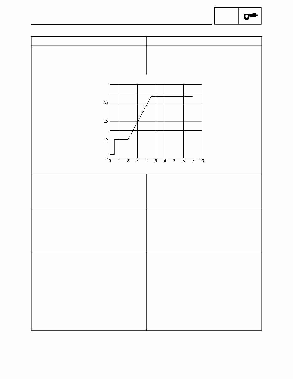
Ignition system:
Ignition timing (B.T.D.C.) 10° at 1,000 r/min
Advanced timing (B.T.D.C.) 33° at 5,000 r/min
Advancer type Digital type
C.D.I.:
Magneto model/manufacturer F4T423/MITSUBISHI
Pickup coil resistance/color 459 ~ 561 Ω at 20 °C (68 °F)/White/Red –
White/Green
C.D.I. unit model/manufacturer F8T38673/MITSUBISHI
Rectifier:
Regulator type Semi conductor-short circuit
Model/manufacturer SH640E-11/SHINDENGEN
No load regulated voltage 14.1 ~ 14.9 V
Capacity 14 A
Withstand voltage 200 V
Circuit breaker:
Type Fuse
Amperage for individual circuit
Main fuse 30 A × 1
Headlight fuse 15 A × 1
Ignition fuse 10 A × 1
Auxiliary DC jack fuse 10 A × 1
Carburetor warmer fuse 10 A × 1
Reserve fuse 30 A × 1
15 A × 1
10 A × 1
Engine speed (× 10³ r/min)
Ignition timing
(B.T.D.C.)
You're Reading a Preview
What's Included?
Fast Download Speeds
Online & Offline Access
Access PDF Contents & Bookmarks
Full Search Facility
Print one or all pages of your manual
$31.99
$41.99
Viewed 84 Times Today


Secure transaction
What's Included?
Fast Download Speeds
Online & Offline Access
Access PDF Contents & Bookmarks
Full Search Facility
Print one or all pages of your manual
$31.99
$41.99
- This complete factory service repair workshop manual is available for instant access on your computer, tablet, or smartphone.
- It covers all repairs, servicing, and troubleshooting procedures with detailed photos and diagrams.
- Professional mechanics and technicians use this manual, which contains step-by-step instructions and highly detailed exploded diagrams and pictures.
- You have the option to print out a single page or the entire manual.
- This manual can be used on multiple computers without any limitations or trial periods.
- There is no expiry date or renewal fee; you can use this manual for life.
- It is fully compatible with Windows and MAC computers.
For more information, please click on the button.


