

1997-1999 Yamaha Big Bear 350 4x4 ATV Service & Repair Manual
What's Included?
Fast Download Speeds
Online & Offline Access
Access PDF Contents & Bookmarks
Full Search Facility
Print one or all pages of your manual
.YAMAHA
YF 350F B
330
YAMAHA
LIT-11616·1 0·58

YFM350FWBJ
SERVICE MANUAL
© 1996 by Yamaha Motor Corporation, U.S.A.
First edition, November 1996
All rights reserved. Any reproduction or
unauthorized use without the written
permission of Yamaha Motor Corporation, U.S.A.
is expressly prohibited.
Printed in U.S.A.
LIT-11616-10-58
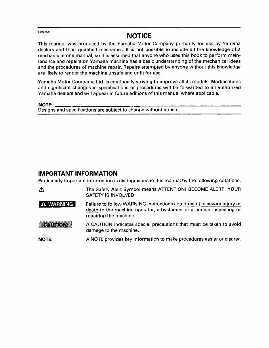
EB001000
NOTICE
This manual was produced by the Yamaha Motor Company primarily for use by Yamaha
dealers and their qualified mechanics. It is not possible to include all the knowledge of a
mechanic in one manual, so it is assumed that anyone who uses this book to perform main-
tenance and repairs on Yamaha machine has a basic understanding of the mechanical ideas
and the procedures of machine repair. Repairs attempted by anyone without this knowledge
are likely to render the machine unsafe and unfit for use.
Yamaha Motor Company, Ltd. is continually striving to improve all its models. Modifications
and significant changes in specifications or procedures will be forwarded to all authorized
Yamaha dealers and will appear in future editions of this manual where applicable.
NOTE: -------------------------------------------------------
Designs and specifications are subject to change without notice.
IMPORTANT INFORMATION
Particularly important information is distinguished in this manual by the following notations.
A WARNING
NOTE:
The Safety Alert Symbol means ATTENTION! BECOME ALERT! YOUR
SAFETY IS INVOLVED!
Failure to follow WARNING instructions could result in severe injury or
death to the machine operator, a bystander or a person inspecting or
repairing the machine.
A CAUTION indicates special precautions that must be taken to avoid
damage to the machine.
A NOTE provides key information to make procedures easier or clearer.
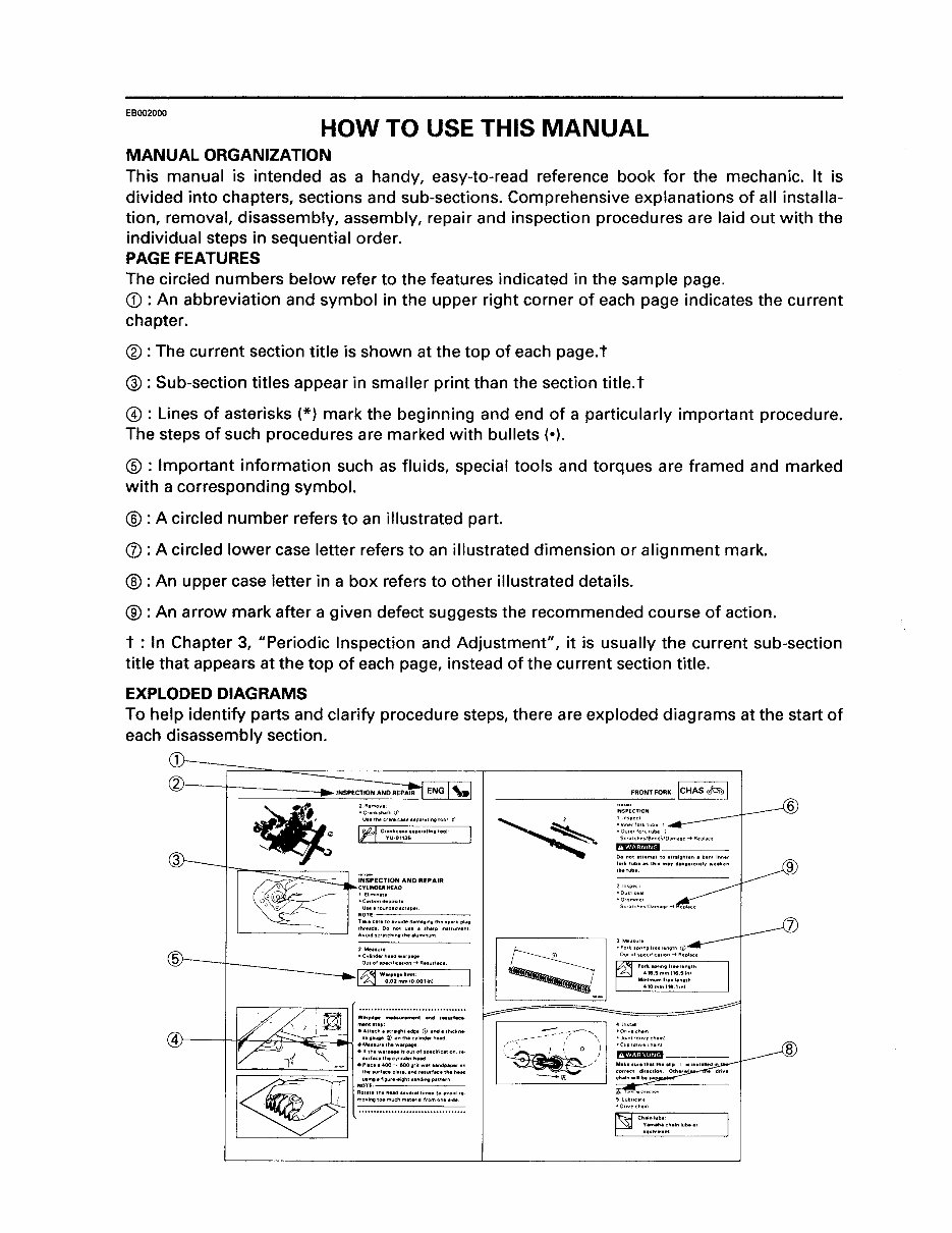
EB002000
HOW TO USE THIS MANUAL
MANUAL ORGANIZATION
This manual is intended as a handy, easy-to-read reference book for the mechanic. It is
divided into chapters, sections and sub-sections. Comprehensive explanations of all installa-
tion, removal, disassembly, assembly, repair and inspection procedures are laid out with the
individual steps in sequential order.
PAGE FEATURES
The circled numbers below refer to the features indicated in the sample page.
CD : An abbreviation and symbol in the upper right corner of each page indicates the current
chapter.
®:The current section title is shown at the top of each page.t
®:Sub-section titles appear in smaller print than the section title.t
@ : Lines of asterisks (*) mark the beginning and end of a particularly important procedure.
The steps of such procedures are marked with bullets (•).
®: Important information such as fluids, special tools and torques are framed and marked
with a corresponding symbol.
® :A circled number refers to an illustrated part.
(j) : A circled lower case letter refers to an illustrated dimension or alignment mark.
® : An upper case letter in a box refers to other illustrated details.
®:An arrow mark after a given defect suggests the recommended course of action.
t : In Chapter 3, "Periodic Inspection and Adjustment", it is usually the current sub-section
title that appears at the top of each page, instead of the current section title.
EXPLODED DIAGRAMS
To help identify parts and clarify procedure steps, there are exploded diagrams at the start of
each disassembly section.
1,-~===--=~------------~-------------------.
2r---T-------~~-------~--~'
• Cran~JI>Ift lJ
Usethecrenkcnesepatl!,ngtool i'
11:1 Cr~~~~~~;:•P.,Itlno tool
•C•rbondeJ)OI•U
Uu•roundedsc,.per
NOTE-----
Tekece<etoevou:ledema;ongtheap•rkplug
thrudt Oo not ute 1 thlrp onsllument
'----------' AvoodiCffttllongthtll<unonum
Warp41 .. me11urement end ttlurfiiCI
mentllep:
eAnechlltraogMadgt <D endathockne
)---H~~ub::::;~;_t;w .:.:.",',':,~.:,:::;:hnde• "'..,
~
etlthtWifPIIgeiiOutOIIC"'CIIocltoon,rl·
- turllctthtcylondarhud
'----'=--=-'-------'':=..J'"" e PIICI I 400 - &00 Qfll wtl Ul'ldplper on
- -. - :~IE~::::::.;:.:::::::::::.:·.~
movongtoomuchmattflllfromonts•dt
····································
_______ FRO_NT_Fo_RK ICHAS~~0~
,~----' -~-( 0 ~\1
' ' I
'
-"'
9
CD ®
1~~~~ I cttel
lsPEcl ~~
®
@
1~:gs1-.1
ENG
~.
~
® ®
lcARBI iii loRivi-F:+-1
(j)
®
lcHAslcfJOI IELEclol
®
@)
~
IJn~~? I
®
E1
@
~
@)
~
@
~
@
§
@
~
®
@) @)
1
l l
m ~ ~
® ®
@
~ ~
......
@
~
A
·~r:ml
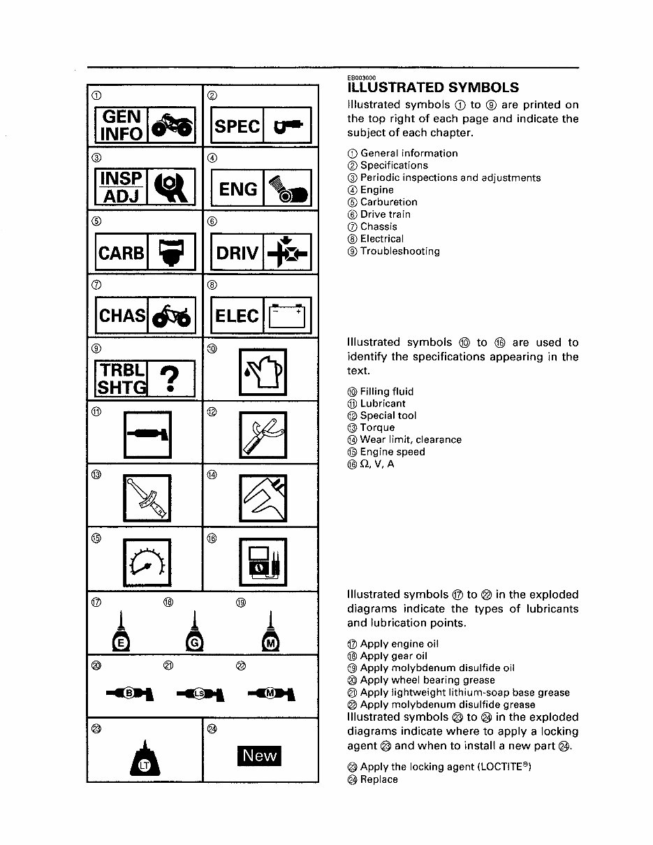
EB003000
ILLUSTRATED SYMBOLS
Illustrated symbols CD to ® are printed on
the top right of each page and indicate the
subject of each chapter.
CD General information
® Specifications
@Periodic inspections and adjustments
@Engine
® Carburetion
®Drive train
(j) Chassis
® Electrical
®Troubleshooting
Illustrated symbols ® to @ are used to
identify the specifications appearing in the
text.
@)Filling fluid
®Lubricant
@Special tool
@)Torque
@Wear limit, clearance
@Engine speed
@Q,V,A
Illustrated symbols @ to @ in the exploded
diagrams indicate the types of lubricants
and lubrication points.
®Apply engine oil
@)Apply gear oil
@)Apply molybdenum disulfide oil
®Apply wheel bearing grease
<@Apply lightweight lithium-soap base grease
@Apply molybdenum disulfide grease
Illustrated symbols® to® in the exploded
diagrams indicate where to apply a locking
agent® and when to install a new part(§.
@Apply the locking agent (LOCTITE®)
~Replace
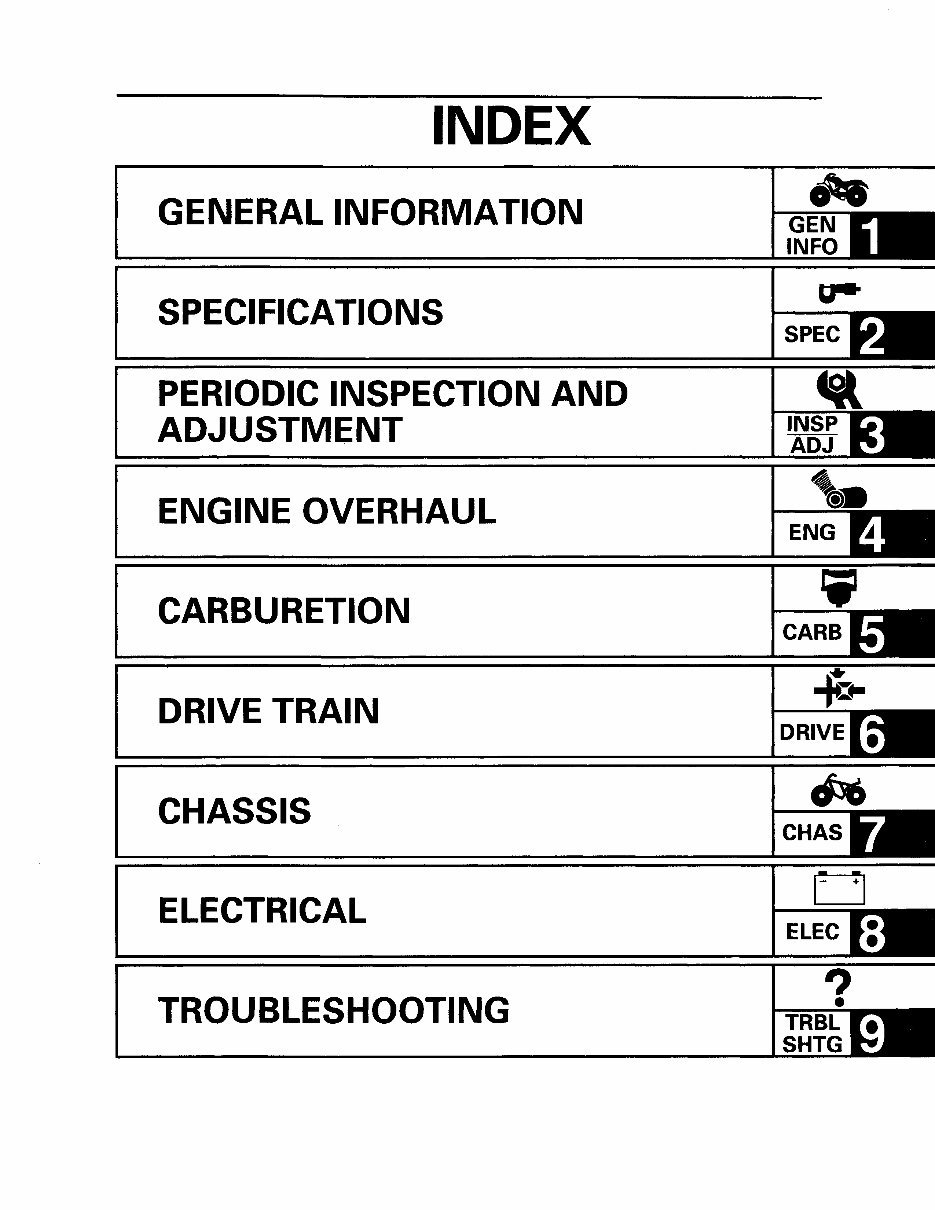
INDEX
GENERAL INFORMATION
SPECIFICATIONS
PERIODIC INSPECTION AND
ADJUSTMENT
ENGINE OVERHAUL
CARBURETION
DRIVE TRAIN
CHASSIS
ELECTRICAL
TROUBLESHOOTING
CHAS
ELEC
TRBL
SHTG
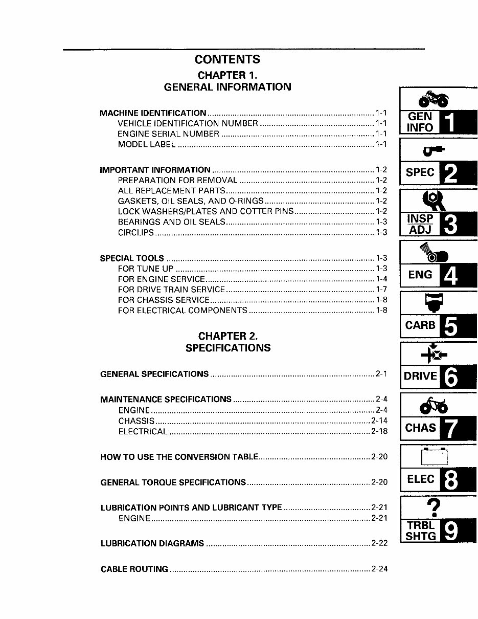
CONTENTS
CHAPTER 1.
GENERAL INFORMATION
MACHINE IDENTIFICATION ......................................................................... 1-1
VEHICLE IDENTIFICATION NUMBER .................................................. 1-1
ENGINE SERIAL NUMBER ................................................................... 1-1
MODEL LABEL ...................................................................................... 1-1
IMPORTANT INFORMATION ....................................................................... 1-2
PREPARATION FOR REMOVAL ........................................................... 1-2
ALL REPLACEMENT PARTS ................................................................. 1-2
GASKETS, OIL SEALS, AND 0-RINGS ................................................ 1-2
LOCK WASHERS/PLATES AND COTTER PINS ................................... 1-2
BEARINGS AND OIL SEALS ................................................................. 1-3
CIRCLIPS ................................................................................................ 1-3
SPECIAL TOOLS ........................................................................................... 1-3
FOR TUNE UP ....................................................................................... 1-3
FOR ENGINE SERVICE .......................................................................... 1-4
FOR DRIVE TRAIN SERVICE ................................................................. 1-7
FOR CHASSIS SERVICE ........................................................................ 1-8
FOR ELECTRICAL COMPONENTS ....................................................... 1-8
CHAPTER 2.
SPECIFICATIONS
GENERAL SPECIFICATIONS ........................................................................ 2-1
MAINTENANCE SPECIFICATIONS .............................................................. 2-4
ENGINE .................................................................................................. 2-4
CHASSIS .............................................................................................. 2-14
ELECTRICAL···························································· ............................ 2-18 CHAS
HOW TO USE THE CONVERSION TABLE ................................................. 2-20 D
GENERAL TORQUE SPECIFICATIONS ...................................................... 2-20 ELEC
LUBRICATION POINTS AND LUBRICANT TYPE ...................................... 2-21
ENGINE ................................................................................................ 2-21
LUBRICATION DIAGRAMS ........................................................................ 2-22
CABLE ROUTING ........................................................................................ 2-24
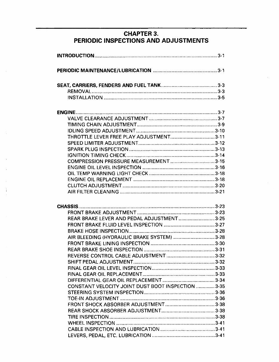
CHAPTER 3.
PERIODIC INSPECTIONS AND ADJUSTMENTS
INTRODUCTION ............................................................................................ 3-1
PERIODIC MAINTENANCE/LUBRICATION ................................................ 3-1
SEAT, CARRIERS, FENDERS AND FUEL TANK .......................................... 3-3
REMOVAL .............................................................................................. 3-3
INSTALLATION ..................................................................................... 3-5
ENGINE .......................................................................................................... 3-7
VALVE CLEARANCE ADJUSTMENT ................................................... 3-7
TIMING CHAIN ADJUSTMENT ............................................................ 3-9
IDLING SPEED ADJUSTMENT ........................................................... 3-10
THROTTLE LEVER FREE PLAY ADJUSTMENT ................................. 3-11
SPEED LIMITER ADJUSTMENT ......................................................... 3-12
SPARK PLUG INSPECTION ................................................................ 3-13
IGNITION TIMING CHECK .................................................................. 3-14
COMPRESSION PRESSURE MEASUREMENT ................................. 3-15
ENGINE OIL LEVEL INSPECTION ...................................................... 3-16
OIL TEMP WARNING LIGHT CHECK ................................................. 3-18
ENGINE OIL REPLACEMENT ............................................................. 3-18
CLUTCH ADJUSTMENT ..................................................................... 3-20
AIR FILTER CLEANING ....................................................................... 3-21
CHASSIS ...................................................................................................... 3-23
FRONT BRAKE ADJUSTMENT .......................................................... 3-23
REAR BRAKE LEVER AND PEDAL ADJUSTMENT ........................... 3-25
FRONT BRAKE FLUID LEVEL INSPECTION ...................................... 3-27
BRAKE HOSE INSPECTION ................................................................ 3-28
AIR BLEEDING (HYDRAULIC BRAKE SYSTEM) ............................... 3-28
FRONT BRAKE LINING INSPECTION ................................................ 3-30
REAR BRAKE SHOE INSPECTION ..................................................... 3-31
REVERSE CONTROL CABLE ADJUSTMENT .................................... 3-32
SHIFT PEDAL ADJUSTMENT ............................................................. 3-32
FINAL GEAR OIL LEVEL INSPECTION ............................................... 3-33
FINAL GEAR OIL REPLACEMENT ...................................................... 3-33
DIFFERENTIAL GEAR OIL REPLACEMENT ....................................... 3-34
CONSTANT VELOCITY JOINT DUST BOOT INSPECTION .............. 3-35
STEERING SYSTEM INSPECTION ..................................................... 3-36
TOE-IN ADJUSTMENT ....................................................................... 3-36
FRONT SHOCK ABSORBER ADJUSTMENT ..................................... 3-38
REAR SHOCK ABSORBER ADJUSTMENT ........................................ 3-38
TIRE INSPECTION ............................................................................... 3-38
WHEEL INSPECTION .......................................................................... 3-41
CABLE INSPECTION AND LUBRICATION ......................................... 3-41
LEVERS, PEDAL, ETC. LUBRICATION ............................................... 3-41
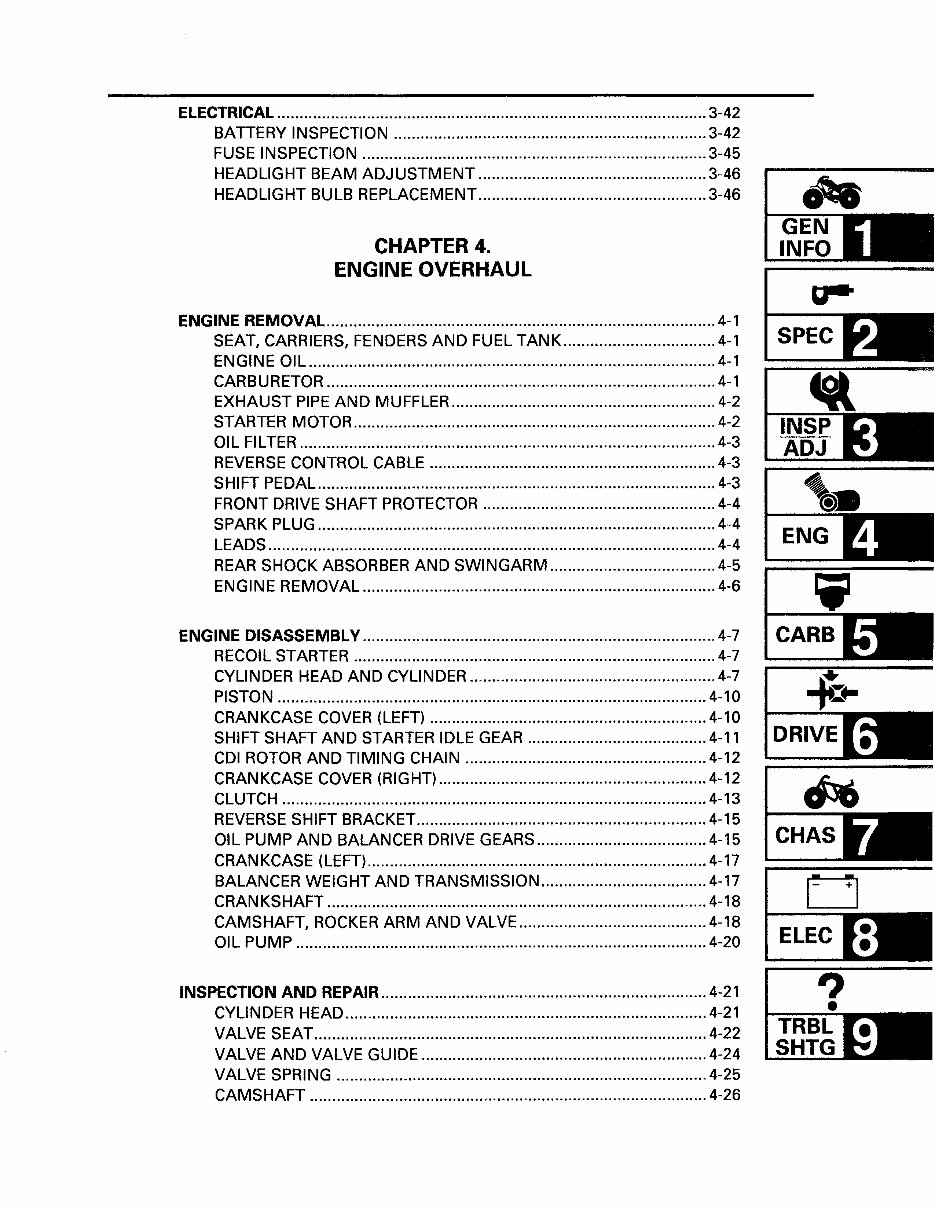
ELECTRICAL ................................................................................................ 3-42
BATTERY INSPECTION ...................................................................... 3-42
FUSE INSPECTION ............................................................................. 3-45
HEADLIGHT BEAM ADJUSTMENT ................................................... 3-46
HEADLIGHT BULB REPLACEMENT ................................................... 3-46
CHAPTER 4.
ENGINE OVERHAUL
ENGINE REMOVAL ....................................................................................... 4-1
SEAT, CARRIERS, FENDERS AND FUEL TANK .................................. 4-1
ENGINE OIL ........................................................................................... 4-1
CARBURETOR ....................................................................................... 4-1
EXHAUST PIPE AND MUFFLER ........................................................... 4-2
STARTER MOTOR ................................................................................. 4-2
OIL FILTER ............................................................................................. 4-3
REVERSE CONTROL CABLE ................................................................ 4-3
SHIFT PEDAL ......................................................................................... 4-3
FRONT DRIVE SHAFT PROTECTOR .................................................... 4-4
SPARK PLUG ......................................................................................... 4-4
LEADS .................................................................................................... 4-4
REAR SHOCK ABSORBER AND SWINGARM ..................................... 4-5
ENGINE REMOVAL ............................................................................... 4-6
ENGINE DISASSEMBLY ............................................................................... 4-7
RECOIL STARTER ................................................................................. 4-7
CYLINDER HEAD AND CYLINDER ....................................................... 4-7
PISTON ................................................................................................ 4-10
CRANKCASE COVER (LEFT) .............................................................. 4-10
SHIFT SHAFT AND STARTER IDLE GEAR ....................................... .4-11
CDI ROTOR AND TIMING CHAIN ...................................................... 4-12
CRANKCASE COVER (RIGHT) ............................................................ 4-12
CLUTCH ............................................................................................... 4-13
REVERSE SHIFT BRACKET ................................................................. 4-15
OIL PUMP AND BALANCER DRIVE GEARS ...................................... 4-15
CRANKCASE (LEFT) ............................................................................ 4-17
BALANCER WEIGHT AND TRANSMISSION ..................................... 4-17
CRANKSHAFT ..................................................................................... 4-18
CAMSHAFT, ROCKER ARM AND VALVE .......................................... 4-18
OIL PUMP ............................................................................................ 4-20
INSPECTION AND REPAIR ......................................................................... 4-21
CYLINDER HEAD ................................................................................. 4-21
VALVE SEAT ........................................................................................ 4-22
VALVE AND VALVE GUIDE ................................................................ 4-24
VALVE SPRING ................................................................................... 4-25
CAMSHAFT ......................................................................................... 4-26
~
~-
ENG
CHAS
D
ELEC
?
You're Reading a Preview
What's Included?
Fast Download Speeds
Online & Offline Access
Access PDF Contents & Bookmarks
Full Search Facility
Print one or all pages of your manual
$31.99
$41.99
Viewed 82 Times Today


Secure transaction
What's Included?
Fast Download Speeds
Online & Offline Access
Access PDF Contents & Bookmarks
Full Search Facility
Print one or all pages of your manual
$31.99
$41.99
- This complete factory service repair workshop manual is available for instant access on your computer, tablet, or smartphone.
- It covers all repairs, servicing, and troubleshooting procedures with detailed photos and diagrams.
- Professional mechanics and technicians use this manual, which contains step-by-step instructions and highly detailed exploded diagrams and pictures.
- You have the option to print out a single page or the entire manual.
- This manual can be used on multiple computers without any limitations or trial periods.
- There is no expiry date or renewal fee; you can use this manual for life.
- It is fully compatible with Windows and MAC computers.
For more information, please click on the button.


