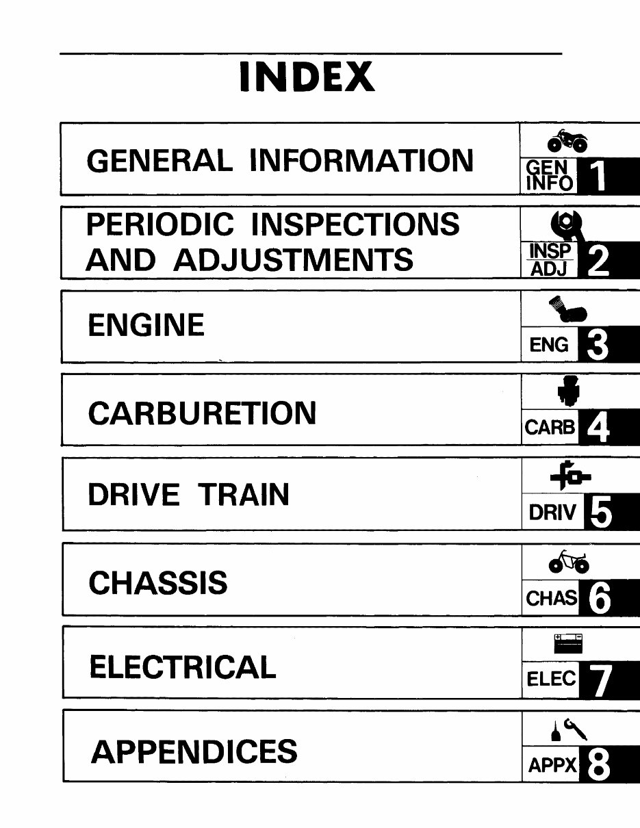
INDEX GENERAL INFORMATION PERIODIC INSPECTIONS AND ADJUSTMENTS ENGINE CARBURETION DRIVE TRAIN CHASSIS ELECTRICAL APPENDICES "- ENG .(D. DR IV iii ELEC ~, APPX
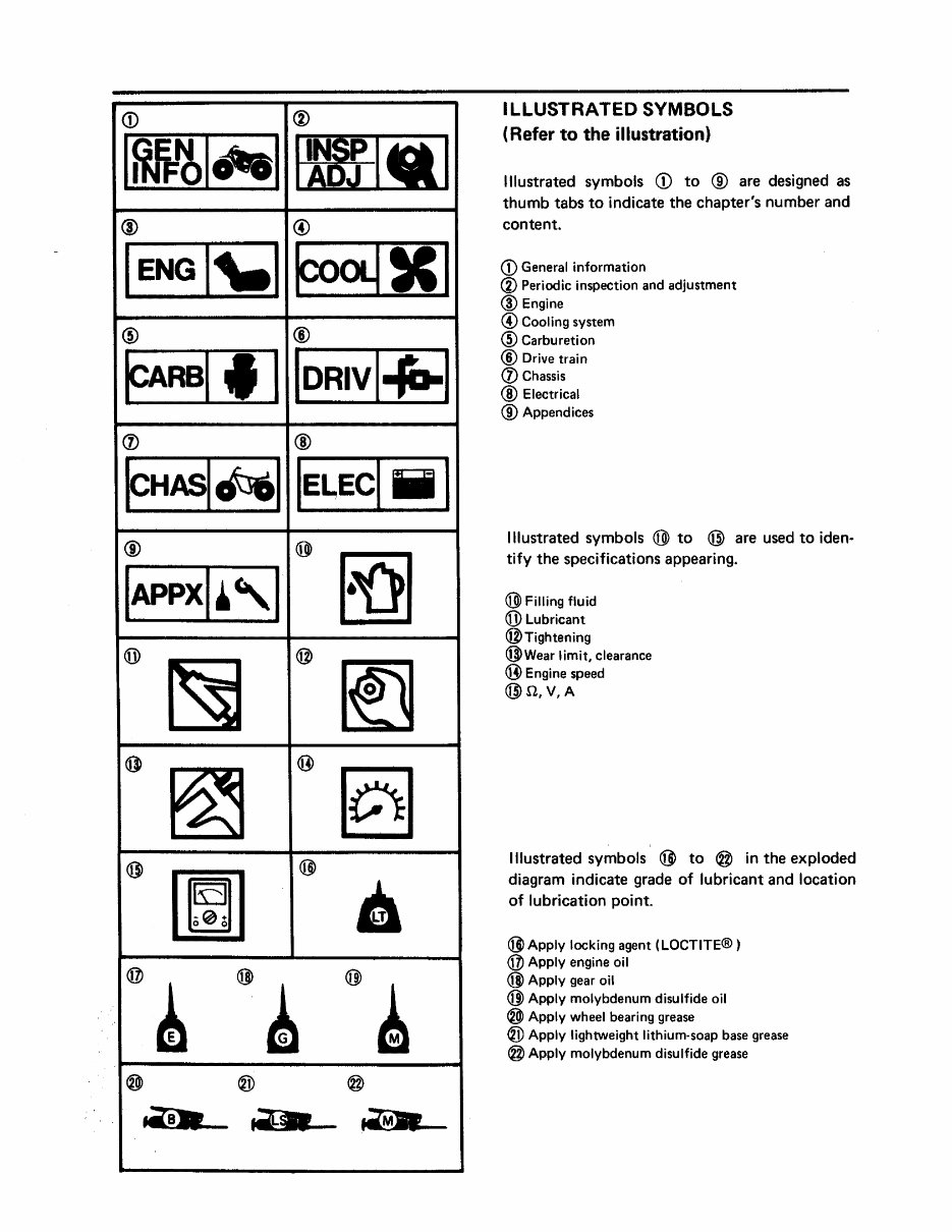
<D (j) 1fm!b1~1 I~I.I ® @ I ENG 1'-1 ~.I @ ® ~RBI f 1 I DRIV 1-1&-1 (j) ® FH~~I IE~ECI iii 1 @ @) ~ IAPPXI~'1 CO) ~ @ If] @ ~ ® § @ [mJ @ • @, @ • @~ ® ® @ _8 .... .--§l1 ~ ILLUSTRATED SYMBOLS (Refer to the illustration) Illustrated symbols CD to ® are designed as thumb tabs to indicate the chapter's number and content. <D General information <i) Periodic inspection and adjustment @ Engine ® Cooling system ® Carburetion ® Drive train (j) Chassis @ Electrical ® Appendices Illustrated symbols @ to @) are used to iden .. tify the specifications appearing. @ Filling fluid CO) Lubricant @Tightening @Wear limit, clearance ® Engine speed @n,V,A Illustrated symbols @ to @ in the exploded diagram indicate grade of lubricant and location of lubrication point. @ Apply locking agent (LOCTITE® ) @ Apply engine oil @ Apply gear oil @ Apply molybdenum disulfide oil ® Apply wheel bearing grease ® Apply lightweight lithium-soap base grease @ Apply molybdenum disulfide grease
CHAPTER 1. GENERAL INFORMATION MACHINE IDENTIFiCATION .................................... 1-1 VEHICLE IDENTIFICATION NUMBER ......................... 1-1 ENGINE SERIAL NUMBER .................................. 1-1 IMPORTANT INFORMATION .................................... 1-2 ALL REPLACEMENT PARTS ................................. 1-2 GASKETS, OIL SEALS, AND O-RINGS ........................ 1-2 LOCK WASHERS/PLATES AND COTTER PINS .................. 1-2 BEARINGS AND OIL SEALS ................................ 1-2 CI RCLIPS ................................................. 1-3 SPECIAL TOOLS .............................................. 1-3 FOR TUNE-UP ............................................. 1-3 FOR ENGINE SERViCE ..................................... 1-4 FOR MIDDLE GEAR SERViCE ............................... 1-7 FOR FINAL GEAR SERVICE .................................. 1-8 FOR DIFFERENTIAL GEAR SERVICE ......................... • 1-8 FOR CHASSIS SERVICE ....................... • ............. • 1-9 FOR ELECTRICAL COMPONENTS ............................. 1-9
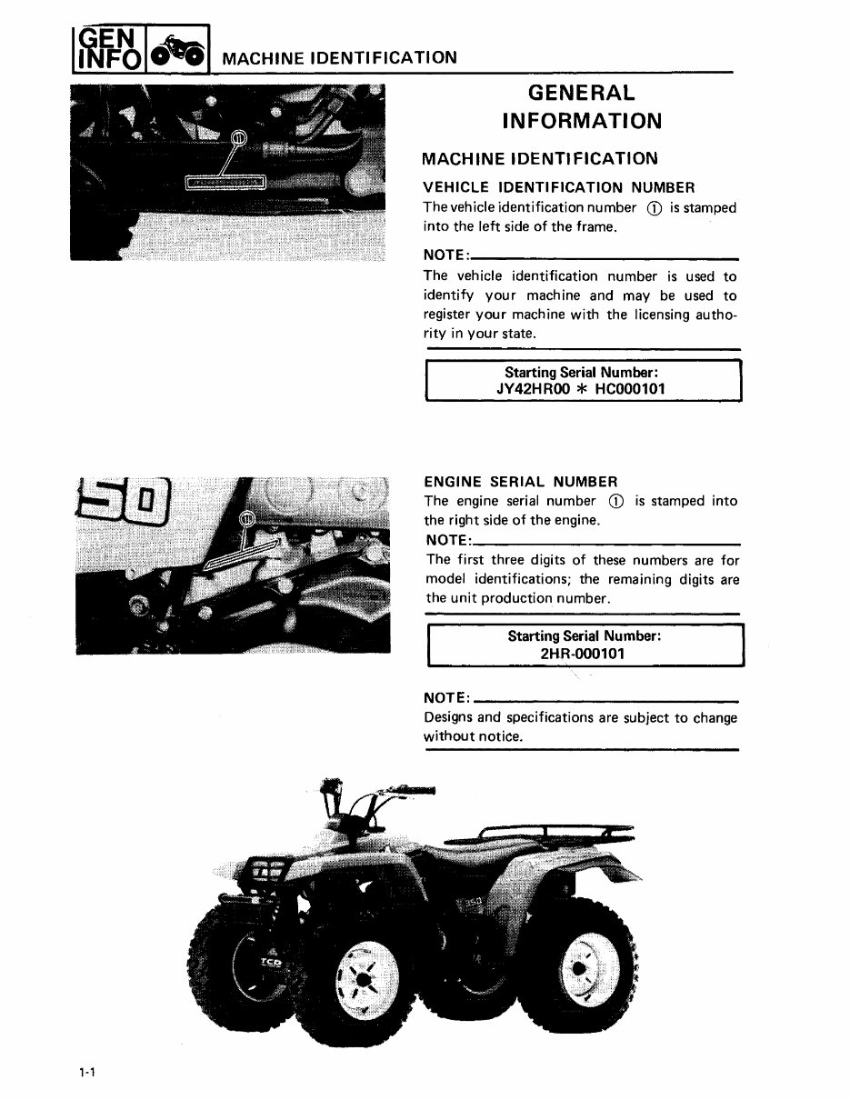
I~l-'bl'-'I MACHINE IDENTIFICATION ,-, GENERAL INFORMATION MACHINE IDENTIFICATION VEHICLE IDENTIFICATION NUMBER The vehicle identification number CD is stamped into the left side of the frame. NOTE: ____________ _ The vehicle identification number is used to identify your machine and may be used to register you r mach ine with the licensing autho- rity in your state. Starting Serial Number: JV42HROO * HC000101 ENGINE SERIAL NUMBER The engine serial number CD is stamped into the right side of the engine. NOTE: __________________________ _ The first three digits of these numbers are for model identifications; the remaining digits are the unit production number. Starting Serial Number: 2HR-000101 " NOTE: ________________________ __ Designs and specifications are subject to change without notice.
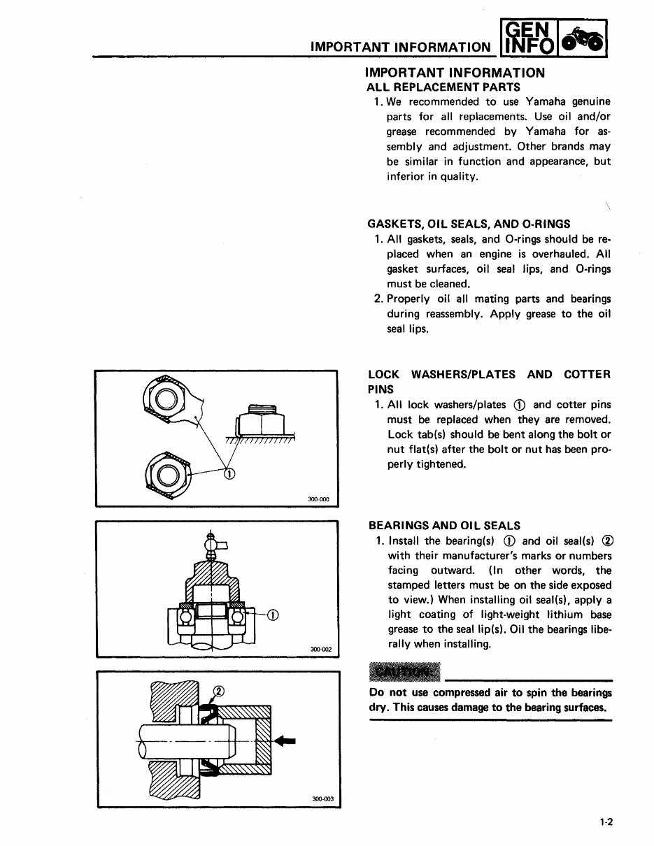
IMPORTANT INFORMATION 1~1J=~lcfeal IMPORTANT INFORMATION 300-000 300-002 300-003 ALL REPLACEMENT PARTS 1. We recommended to use Yamaha genuine parts for all replacements. Use oil and/or grease recommended by Yamaha for as- sembly and adjustment. Other brands may be similar in function and appearance, but inferior in quality. \ GASKETS, Oil SEALS, AND O·RINGS 1. All gaskets, seals, and O-rings should be re- placed when an engine is overhauled. All gasket surfaces, oil seal lips, and a-rings must be cleaned. 2. Properly oil all mating parts and bearings during reassembly. Apply grease to the oil seal lips. LOCK WASHERS/PLATES AND COTTER PINS 1. All lock washers/plates CD and cotter pins must be replaced when they are removed. Lock tab(s) should be bent along the bolt or nut flat(s) after the bolt or nut has been pro- perly tightened. BEARINGS AND OIL SEALS 1. Install the bearing(s) CD and oil seal(s) @ with their manufacturer's marks or numbers facing outward. (In other words, the stamped letters must be on the side exposed to view.) When installing oil seal(s), apply a light coating of light-weight lithium base grease to the seal lip(s). Oil the bearings libe- rally when installing. Do not use compressed air to spin the bearings dry. This causes damage to the bearing surfaces. '-2
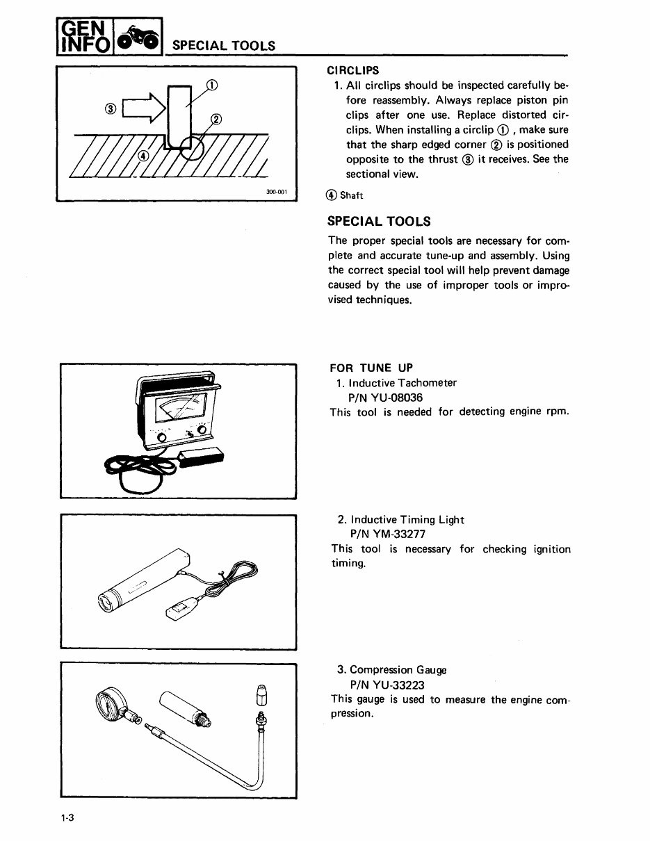
I~~I"'I SPECIAL TOOLS 300·001 '·3 CIRCLIPS 1. All circlips should be inspected carefully be- fore reassembly. Always replace piston pin clips after one use. Replace distorted cir- clips. When installing a circlip CD , make sure that the sharp edged corner ® is positioned opposite to the thrust @ it receives. See the sectional view. @Shaft SPECIAL TOOLS The proper special tools are necessary for com- plete and accurate tune-up and assembly. Using the correct special tool will help prevent damage caused by the use of improper tools or impro- vised techniques. FOR TUNE UP 1. I nductive Tachometer PIN YU-08036 This tool is needed for detecting engine rpm. 2. Inductive Timing Light PIN YM-33277 This tool is necessary for checking ignition timing. 3. Compression Gauge PIN YU-33223 This gauge is used to measure the engine com- pression.
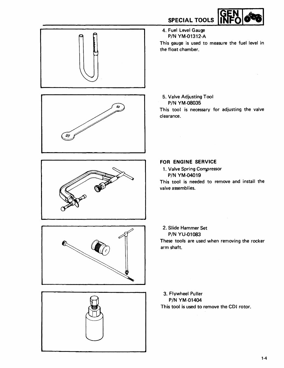
SPECIAL TOOLS 4. Fuel Level Gauge PIN YM·01312·A This gauge is used to measure the fuel level in the float chamber. 5. Valve Adjusting Tool PIN YM-08035 This tool is necessary for adjusting the valve clearance. FOR ENGINE SERVICE 1. Valve Spring Co")pressor PIN YM·04019 This tool is needed to remove and install the valve assembl ies. 2. Slide Hammer Set PIN YU-Ol083 These tools are used when removing the rocker arm shaft. 3. Flywheel Puller PIN YM-01404 This tool is used to remove the CDI rotor. 1-4
Get your hands on a comprehensive Workshop Service and Repair Manual for the 1987-1997 Yamaha Big Bear 350 ATV, covering both 2wd and 4x4 models. This improved manual comes with bookmarks, searchable text, and an index for the best organization.
Whether you're a professional mechanic or a DIY enthusiast, this manual contains all the information you need to repair, maintain, rebuild, refurbish, or restore your motorcycle. It includes detailed instructions for complete tear down and rebuild, along with pictures, part diagrams, torque specs, maintenance procedures, and troubleshooting guidelines.
The manual covers a wide range of topics including general information, periodic maintenance, engine, shaft drive and differential, fuel and lubrication system, cooling system, chassis, electrical system, service information, index, and wiring diagrams. Additionally, it includes supplement manuals for the 1989, 1990, 1991, 1994, 1996, and 1997 Big Bear 350 4x4 models.
With a total of 438 pages, this manual is available in a printable file format without any restrictions. Upon completing the payment, you will receive a download link on the checkout page. The only requirement for accessing the manual is Adobe Reader.
Investing in the right repair manual for your motorcycle can save you a significant amount of money and provide you with valuable insights into your vehicle. Take advantage of the preview option to see some sample pages before making your decision.
Customer satisfaction is guaranteed, and by opting for instant download, you can save on repair and maintenance costs without the need for shipping or waiting for a physical textbook to arrive. Don't hesitate any longer – get this manual now and complete all your repairs today for full value for your money!
File Format: PDF
Total Pages: 438 pages
Printable: Yes
Delivery: Instant download link
Requirements: Adobe Reader
Recently Viewed
5,521,897Happy Clients
2,594,462eManuals
1,120,453Trusted Sellers
15Years in Business
Price:
Actual Price:
19987-1997 Yamaha Big Bear 350 Service Repair Manual YFM350 (Highly Detailed FSM, Preview)

")