

Kawasaki Tecate 4 service manual repair 1987-1988 KXF250
What's Included?
Fast Download Speeds
Online & Offline Access
Access PDF Contents & Bookmarks
Full Search Facility
Print one or all pages of your manual
KXF250
Kawa ki CATE 4
All Terrain Vehic e
Service Manual
First Editi on CD: p r. 24, 1987 CD
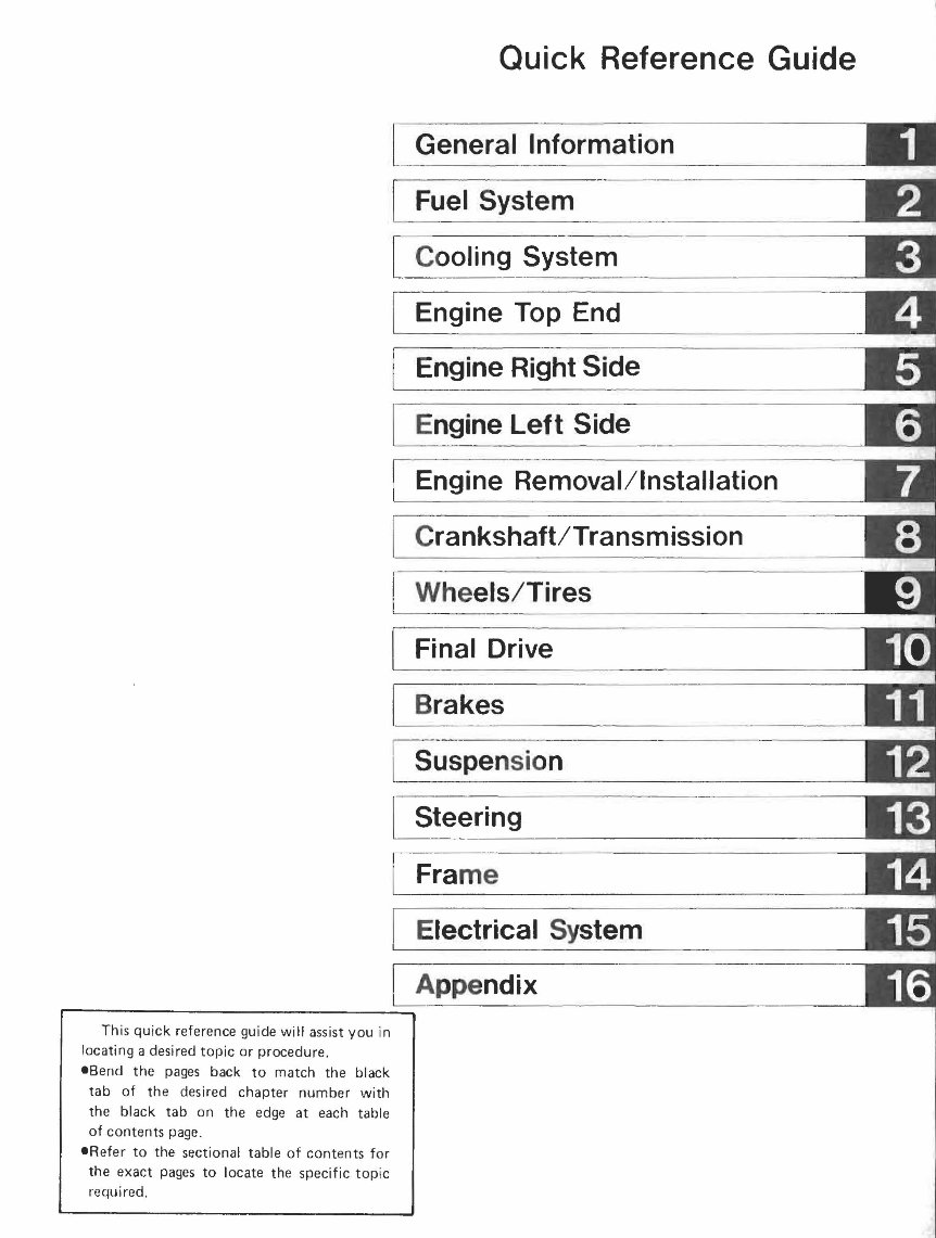
This qu ick reference guide will assist you in
locating a desired topic or procedure .
eBend the pages back to match the black
tab of the desired chapter number with
the black tab on the edge at each table
of contents page.
eR e fer to the sectional table of contents for
the exact pages to locate the specific top ic
required .
Quick Reference Guide
General Information
Fuel System
Cooling System
Engine Top End
Engine Right Side
Engine Left Side
Engine Removal/Installation
Cra nkshaft/Tra nsm ission
Whe els/Tires
Final Drive
Brakes
Suspension
Steering
Fra me
Electrical System
Appendix
... , ",.,. .. .
• •• .' ••• • .... 1
:7r:
· ...
· ..
...
· ..
· . . .
· .
III.
........ -
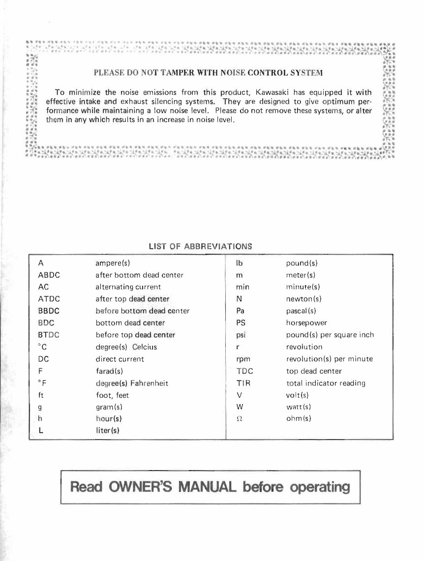
PLEASE 00 NO T TAMPER WITH NOISE CONTROL SY STEM
To mi n im ize the noise emissions from this prod uct, Kawasaki has equipped it with
effective intake and exhaust silencing sys te ms. They are designed to give op timum per-
fo rma nce while maintaining a low noise level. Please do not remove these systems , or alter
the m in any which results in an increase in noise level.
LI ST OF ABBREVIATI ONS
A ampere(s) Ib pound(s)
ABDC after bottom dead center m meter(s)
AC alternating current min minute(s)
ATDC after top dead center N newton(s)
BBDC before bottom dead center Pa pascal (s)
BDC bottom dead center PS horsepower
BT DC before top dead center psi pound(s) per square inch
°C degree(s) Celcius r revolution
DC direct current rpm revolution(s) per minute
F farad(s) TD C top dead center
OF
degr ee(s) Fah ren heit TIR to tal indicator reading
ft foot, feet V volt(s)
g gram(s) W watt(s)
h ho u r(s) n ohm(s)
L liter(s)
Read OWNER'S MANUAL before operating
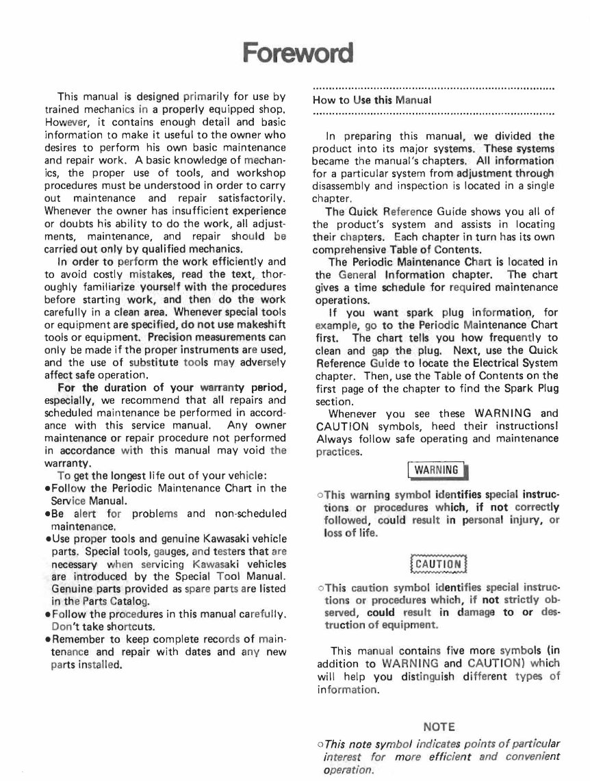
Foreword
This manual is designed primarily for use by
trained mechanics in a properly equipped shop.
Howeve r, it contains enough detail and basic
information to make it useful to the owner who
desires to perform his own basic maintenance
and repair work. A basic knowledge of mechan-
ics, the proper use of tools, and workshop
procedures must be understood in order to carry
out maintenance and repair satisfactorily.
Whenever the owner has insufficient experience
or doubts his ability to do the work, all adjust-
ments, maintenance, and repair should be
carried out onlv by qualified mechanics.
In order to perform the work efficiently and
to avoid costly mistakes, read the text, thor-
oughly familiarize yoursel~ with the procedures
before starting work, and then do the work
carefully in a clean area. Whenever special tools
or equipment are specified, do not use makeshift
tools or equ ipment. Precision measurements can
only be made if the proper instruments ar e used,
and the use of substitute too ls may adversely
affect safe operation.
For the duration of your warran ty period,
especially, we recommend that all repairs and
scheduled maintenance be performed in accord-
ance with this service manual. Any owner
maintenance or repair procedure not performed
in accordance wi th this manual may void the
warranty.
To get the longest life out of your veh ic le:
eFoliow the Periodic Maintenance Chart in the
Serv ice Manual.
eBe alert for problems and non-scheduled
maintenanc e.
eUse proper tools and genuine Kawasaki vehicle
parts. Special to ols, gauges, and testers that are
necessary when serv icing Kawasa ki vehicles
are introduced by the Special Tool Manual.
Genuine parts provided as spare par ts are listed
in th e Part s Catalog.
e Follow the procedures in this manual carefully.
Don 't take shortcuts.
eRemember to keep complete records of ma in-
ten ance and repair with dates and any new
parts in stalle d.
How to Use this Manual
In preparing this manual, we divided the
product into its major systems. These !i)'st,ems
became the manual's chapters. All information
for a particular system from adjustment through
disassembly and inspection is located in a single
chapter.
Th e Quick Reference Guide shows you all of
the product's system and assists in locating
their chapters. Each chapter in turn has its own
comprehensive Table of Contents.
The Periodic Maintenance Ch art is located in
the General Informati· on chapter. The chart
gives a time schedule for requ ired maintenance
operations.
If you want spark plug infor mation, for
exa mp le, go to the Periodic Ma intenance Chart
first. The chart tells you how frequ ent ly to
clean and ga p the plug. Next, use the Quick
Reference Guide to locate the Electrical System
chapter. Then, use the Table of Contents on the
first page of the chapter to find the Spark Plug
section.
Whenever you see these WARNING and
CAUTION symbols, heed their instructionsl
Always follow safe operating and maintenance
pract ices.
C WA RN ING '
oThis warning symbol i dentifies special instruc-
tions or procedures wh ich, if not correctly
followed , co uld result in personal injury, or
loss of life.
o This caution symbol id ent ifies special instruc-
tions or procedures which, if not strictly ob-
served, could result in damage to or des-
tru ct ion of equipment.
This manual contains five more symbo ls (in
addition to WARN I NG and CAUT ION) which
will help you distinguish different types of
in format ion.
NOTE
o This note symbol indicates points of particular
interest for more effi cient and convenient
operation.
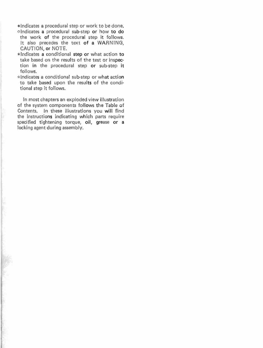
elndicates 8 procedural step or work to be done .
o Indicates a procedural sub- step or how to do
the work of the procedural step it fo ll ows.
It also precedes the text of a WARNING,
CAUTION, or NOTE.
*Indicates a conditional step or what action to
take based on the results of the test or inspec-
tion in the procedural step or sub- step it
follows.
*Indicates a conditional sub-step or wh at actio n
to take based upon the resu lts of the condi-
tional step it follows.
In most chapters an exploded view ill us tr ation
of the system components fo llo ws t he Ta bl e of
Contents_ In these illustrations you will find
the instructions indicating which parts require
specified tightening torque, oil, grease or a
locking agent during assembly.
GENERAL INFORMATION 1-1
General Information
Ta ble of Contents
Before Servicing . . . . . . . . . . . . . . . . . . . . . . . . . . . . . . . . . . . . . . . . . . . 1-2
Model Identification . . . . . . . . . . . . . . . . . . . . . . . . . . . . . . . . . . . . . . . . 1·4
General Specifications ... .. ........... . ..................... 1-5
Cable and Harness Routing. . . . . . . . . . . . . . . . . . . . . . . . . . . . . . . . . . . 1·10
Periodic Maintenance Chart ... . . . . . . . . . . . . . . . . . . . . . . . . . . . . . .. 1- 12
1-2 GE NERAL INFOR MATION
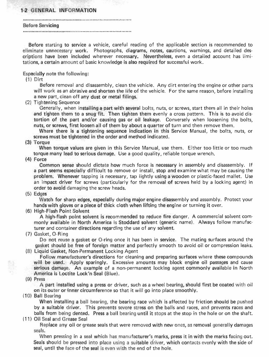
Before Servicing
Before startin g to service a vehicle, careful reading of the applicable section is recommended to
eliminate unnecessary work. Photographs, diagrams, no,tes, cautions, warnings, and detailed des-
cripti ons have been included wherever necessary. Nevertheless, even a detailed account has limi-
tations, a certain amount of basic knowledge is also requir ed for successful work.
Especially note the following:
( 1) Di rt
Before removal and disassembly, clean the vehicle. Any dirt entering the engine or other parts
will work as an abrasive and shorten the life of the vehicle. For the same reason, before install ing
a new part, clean off any dust or meta l filings.
(2) Tightening Sequence
Generally, when installing a part with several bo lts, nuts, or screws, start them all in their holes
and tig hten them to a snug fit. Then tighten them evenly a cross pattern. This is to avoid dis-
t ortion of the p' art and/or causing gas or o, il 'leakage. Conversely when loosening the bolts,
nuts, or screws, 1irst loosen all of them by about a qu art er of turn and then remove them.
Where there is a tightening sequence Indication in this Service Manual, the bolts, nuts, or
screws must be tight ened in the order and method indicated.
(3.) Torque
When to rque values are given in this Service Manual, use them. Either too little or too much
torque many ll ead to serious damage. Use a good qual ity, reliable torque wrench.
(4) Fo rce
Common sense should dict at e how much force is necessary in assembly and disassembly. If
a part seems e·specially dif f ic ult to remove or install , stop and examine what may be causing the
problem. Whenever tapping is necessary, tap lightly using a wooden or plastic-faced mallet. Use
an Impact driver for screws (particularly for the removal of screws held by a locking agent) in
order to avoid damaging the screw heads.
(5) Edges
Wa tch for sharp edges" especially during major engine disassembly and assembly. Protect your
hands" with gloves or a piece of t bick cloth whe n lifting the engine or turning it over.
(6) High-Flash Point So lvent
A high-flash pOl int ,solvent is recommended to reduce fire danger. A commercial solvent com-
monly available in North America is St oddard solvent (generic name). Always follow manufac-
turer and container direct ions regarding the use of any solvent.
(7) Gask et, O-Ring
Do not reuse a gask et or O-ring once it has been in service. The mating surfaces around the
gask et should be free of for e ign matt er and perfectly smooth to avoid oil or compression leaks.
(8) Liquid Gasket, Non-Pe rmanent Locking Agent
Fo llow manufac turer's directions for cleaning and preparing surfaces wher e these compounds
will be used. Apply sparingly. Excessive amounts may block engine oil passages and cause
serious dam age. An ex ample of a non-permanent lOCki ng age nt commonly available in North
America is L octite Lock'n Seal (Blue).
(9) Press
A part installed using a press or driver, such as a wheel bearing, should first be coated with oil
on i ts ou ter or inner circumference so that it will go into place smoothly.
(10) Ball Beari ng
When installing a ball bearing, t he bearing race whic h is affected by friction should be pushed
by a suitable driver. Th is prev ent s severe stress on the balls and races, and preve nts races and
balls from being dented. Press a ba ll bear ing until it stops at the stop in the hole or on the shaft.
(11) Oil Seal and Grease Seal
Replace an y oil or grease seals that were removed with new ones , as remo val gen erall y dam ages
seals.
When pressing in a seal which has manufacturer' s marks, press it in with the marks facing out.
Seals should be pressed into place using a su itable d'river, which con tacts evenly with the side of
seal, until the face of the seal is even wit h the end of the hole.
GENERAL INFORMATION 1-3
(12) Seal Guide
A seal guide is required for certain oil or grease seals during installation to avoid damage to the
seal lips. Before a shaft passes through a seal, apply a little high temperature grease on the lips to
reduce rubber to metal friction.
(13) Circlip, Retaining Ring
Replace any circlips and retaining rings that were removed with new ones, as removal weakens
and deforms them. When installing circlips and retaining rings, take care to compress or expand
them only enough to install them and no more.
(14) Lubrication
Engine wear is generally at its maximum while the engine is warming up and before all the
rubbing surfaces have an adequate lubricative film. During assembly, oil or grease (whichever is
more suitable) should be applied to any rubbing surface which has lost its lubricative film. Old
grease and dirty oil should be cleaned off . Deteriorated grease has lost its lubricative quality and
may contain abrasive foreign particles.
Don't use just any oil or grease. Some oils and greases in particular should be used only in
certain applications and may be harmful if used in an application for which they are not intended.
This manual makes reference to molybdenum disulfide grease (MoS
2
) in the assembly of certain
engine and chassis parts. Always check manufacturer recommendations before using such special
lubricants.
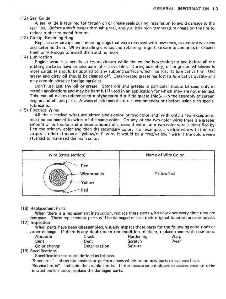
(15) Electrical Wires
All the electrical wires are either single~Qlor or two - color and, with only a few exceptions,
must be connected to wires of the same co'lor. On any of the two-color wires there is a greater
amount of one color and a lesser amount of a second color, so a two-color wire is identified by
first the primary color and then the secondary color. For example, a yellow wire with thin red
stripes is referred to as a "y , ellow/red" wire; it would be a "red/yellow" wire if the colors were
reversed to make red the main color.
Wire (cross-section) Name of Wire Color
~~!d"":--r- Wire strands
Yellow/red
Yellow
(16) Replacement Parts
When there is a replacement instruction, rep lace these parts with new ones every time they are
removed. These replacement parts will be damaged or lose their original function once removed.
(17) Inspection
When parts have been disassembled, visual1 ly inspect these parts f or the following con ditions or
other damage. If there is any doubt as to tile condition of them, replace them with new ones.
Abrasion Crack Hardening Warp
Bent Dent Scratch Wear
Color change Det erior ation Seizure
(18) Specifications
Specification term s are defined as follows.
"Standards" show dimensi ons or p erformances which brand-new parts or systems have.
"Service limits" indicate the usable limits. If the measurement shows excessive wear or dete-
riorated performan ce, rep lace the damaged parts .
1-4 GE NE RAL INFO RM ATION
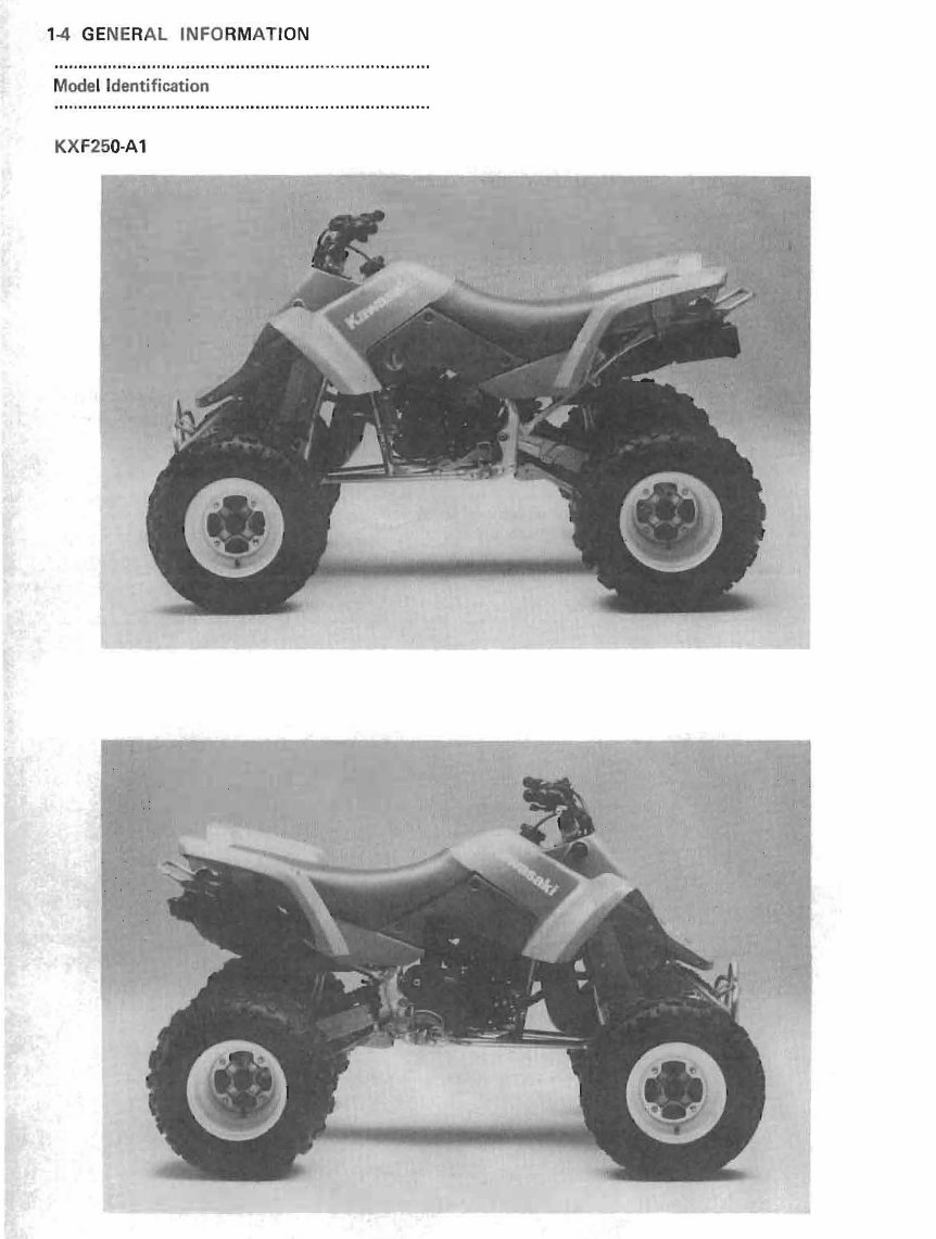
Model Identification
KXF250-A1
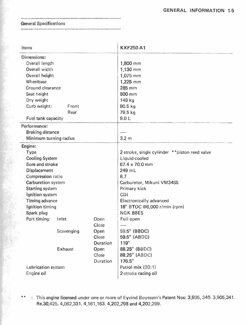
Gen era l Spec ifi cations
Items
Dimensions:
Overall length
Overall width
Overall height
Wheelbase
Grou nd clearance
Seat height
Dry weight
Curb weight: Front
Rear
Fue l tank capacity
Performan ce:
Braking distance
Minimum turning radius
I KXF2 50 -A1
1 1.800 mm
1,130 mm
1,075 mm
1,225 mm
285mm
800mm
149 kg
80.5 kg
79.5 kg
9.0 L
3.2 m
GENERAL INFORMATION 1-5
-- -------- ------+--- ----- ------ -------- -- -------- -- -
Engine:
**
Type
Cooling System
Bo re and stroke
Displacement
Co mpression ratio
Carburetion system
Starting system
Ignition system
Timing advance
Ignition timing
Spark plug
P ort timing: Inlet
Scavenging
Exhaust
Lubrication system
Eng ine oil
Op en
Cl ose
Open
Cl ose
Duration
Open
Close
Duration
2-strok e, single cylinder **piston reed valve
Liqu id-cooled
67.4 x 70.0 mm
249 mL
8.7
Carburetor, Mikuni VM34SS
Primary kick
CDI
Electronically advanced
18° BTDC @6,000 r/min (rpm)
NGK B8ES
Full open
59.5
0
(BBDC)
59.5° (ABDC)
119
0
88.25° (B BDC)
88.25° (ABDe l
176.5°
Petrol mix (20: 1)
2-stroke racing oil
This engine licensed under one or more of Eyvind Boyessen's Patent Nos: 3,9 05 , 340.3,905,341.
Re.30,425. 4,062,331. 4,161,163. 4,2 02 ,298 and 4,202/299.
You're Reading a Preview
What's Included?
Fast Download Speeds
Online & Offline Access
Access PDF Contents & Bookmarks
Full Search Facility
Print one or all pages of your manual
$31.99
Viewed 34 Times Today


Secure transaction
What's Included?
Fast Download Speeds
Online & Offline Access
Access PDF Contents & Bookmarks
Full Search Facility
Print one or all pages of your manual
$31.99
Get your hands on the comprehensive repair manual for the 1987-1988 Kawasaki Tecate 4 two-stroke ATV. This manual covers a complete tear down and rebuild, including detailed pictures and part diagrams, torque specifications, maintenance procedures, troubleshooting guides, and much more. With 203 pages of valuable information, this manual is a must-have for professional mechanics and DIY enthusiasts alike.
Featuring clickable chapters and a searchable interface, finding the information you need has never been easier. There are no restrictions on printing or saving/burning to disc, providing you with the flexibility to access the manual in the way that suits you best.
- Complete tear down and rebuild
- Detailed pictures and part diagrams
- Torque specifications
- Maintenance procedures
- Troubleshooting guides
- Clickable chapters
- Searchable interface
- No restrictions on printing or saving/burning to disc


