

CFMOTO Z8 (CF800) Service & Repair Manual
What's Included?
Fast Download Speeds
Offline Viewing
Access Contents & Bookmarks
Full Search Facility
Print one or all pages of your manual
07 INTAKE MANIFOLD, CYLINDER HEAD AND CYLINDER
07-4

01-1
01 GENERAL INFORMATION
Maintenance information…………..............
1-1
Tightening torque table........................
1-12
Location of VIN /EIN…………………...........
1-3
Lubricants and service products..........
1-19
General specifications………………...........
1-4
MIL/ EVAP system...............................
1-20
Maintenance specifications………..............
1-6
MAINTENANCE INFORMATION
Operation cautions
1. Engine exhaust fumes are poisonous and can result in loss of consciousness or death. Do not run
the engine in an enclosed or poorly ventilated area.
2. Do not touch the engine or muffler with bare hands after the engine has been just stopped to avoid
burns. Wear long-sleeve work clothes and gloves for operation.
3. Battery electrolyte (dilute sulfuric acid) is highly caustic and can result in burns from contact with
skin and eyes. If you spill electrolyte on skin, flush with water and seek for medical attention imme-
diately. If you spill electrolyte on clothes, flush with water to avoid burns. Keep battery and electro-
lyte out of reach of children.
4. Coolant is poisonous. Do not drink or spill it on skin, eyes or clothes. If you spill coolant on skin, im-
mediately wash with soap and water. If you spill coolant on eyes, flush with water and seek prompt
medical attention. If you swallow coolant, induce vomit and see the doctor. Keep coolant out of
reach of children.
5. Wear proper work clothes, cap and boots. If necessary, wear dust-glass, gloves and mask.
6. Gasoline is highly flammable. No smoking or fire. Also keep gasoline away from sparks. Vaporized
gasoline is also explosive. Operate in a well-ventilated area.
7. When the battery is being charged, it produces explosive gases. Charge the battery in a well-venti-
lated area.
8. Be careful not to get pinched by the turning parts like wheels and clutch.
9. When more than two people are operating, keep reminding each other for safety purpose.
Cautions for removal and installation
1. Use genuine CFMOTO parts, lubricants and service products.
2. Clean mud, dust before servicing.
3. Store the removed components separately in order for correct installation.
4. Replace the removed washers, o-rings, piston pin retainers, cotter pins with new ones.
5. Elastic retainers might get distorted after disassembled. Do not use the loosened retainers.
6. Clean and blow off the detergent after removal. Apply lubricants on the surface of moving parts.
Measure the data during removal for correct installation.
7. If you do not know the length of screws, install the screws one by one and make sure they are
screwed in with the same depth.
8. Check if the removed rubber parts are aged and replace if necessary. Keep the rubber parts away
from grease.
9. Pre-tighten the bolts, nuts and screws, then torque to specification. The basic sequence is from big
to small, from inner side to outer side and criss-cross.
10. Replace aged rubber parts when assembling. Do not splash gasoline, grease onto the surface,as
this could cause damage.
11. Apply or inject recommended lubricant to the specified lubrication points.
12. Use special tools when necessary.
13. When ball bearing is removed by pressing steel balls, it can not be reused.
14. Finger turn the inner and outer rings of ball bearing to make sure the bearing will turn smoothly.
• Replace if the axial or radial play is too big.
• If the surface is uneven, clean with oil and replace, if the cleaning does not work.
• When pressing the bearing into the machine or onto the shaft,if the bearing can not be securely
seated, replace it.

01-2
01 GENERAL INFORMATION
15.Install the one-side dust-proof bearing in the right direction. When assembling the open type or
double-side dust-proof bearing, install with manufacturer’s mark outward.
16. Keep the bearing block still when blowing dry the bearing after washing clean. Apply oil or lubricant
before installation.
17. Install the elastic circlip properly. Turn the circlip after assembling to make sure is has been in-
stalled into the slot.
18. After assembling, check if all the tightened parts are properly tightened and can move smoothly.
19. Brake fluid and coolant may damage painting, plastic and rubber parts. Flush with water if splashed
on these parts.
20. Install oil seal with the side of manufacturer’s mark outward.
• Do not fold or scratch the oil seal lip.
• Apply grease to the oil seal lip before assembling.
21. When installing pipes, insert the pipe till the end of joint. Fit the pipe clip, if any, into the groove. Re-
place the pipes or hoses that cannot be tightened.
22. Do not mix mud or dust into engine and/or the hydraulic brake system.
23. Clean the gaskets and washers of the engine casing before assembling. Remove the scratches on
the joint faces by polishing evenly with an oilstone.
24. Do not twist or bend the cables too much. Distorted or damaged cables may cause poor operation
and damage.
25. When assembling the parts of protection caps, insert the caps to the grooves, if any.
ENGINE BREAK-IN
There are many movable components inside the engine, such as piston, piston ring, cylinder,
crankshaft, gears and so on. During initial use period, proper run-in for every critical component
is necessary. Break-in can help engine components match each other better and adjust working
condition. Careful treatment of a new engine will result in more efficient performance and a longer
service life.
Recommended break-in period: First 20 hours
Operation guide:
0~10 Hours
Do not operate continuously at more than 50% throttle position.
Cool down the engine for every 5~10 minutes after every 1 hour operation.
Avoid sudden acceleration. Vary the throttle position slowly and smoothly. Do not vary the throttle
position rapidly.
10~20 Hours
Avoid long-time run at more than 75% throttle position. Do not open throttle completely during the
period.
ATTENTION:
1. Maintain and repair as regular procedures during break-in period.
2. After break-in, do not forget to check and maintain the engine before normal use.
01-3
01 GENERAL INFORMATION
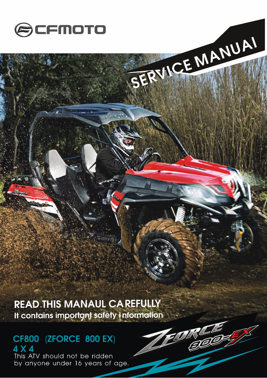
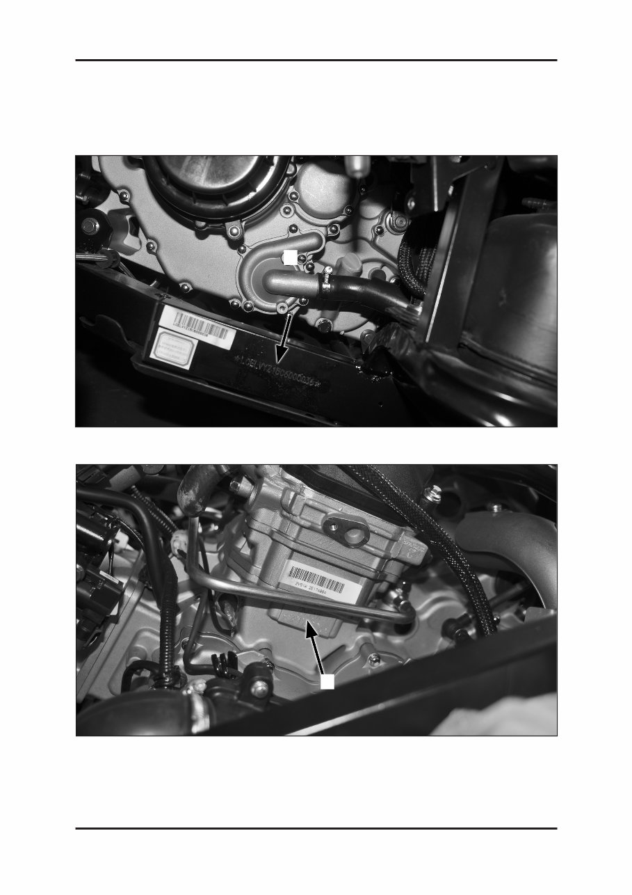
LOCATION OF VIN/EIN
Model Number CF800
1. Vehicle identification number(VIN): LCELVYZ4 ~
2. Engine identification number(EIN): 2V91W ~
1
2

01-4
01 GENERAL INFORMATION
Item Specifications
Model type CF800
Overall length 2870mm
Overall width 1510mm
Overall height 1830mm
Wheelbase 2040mm
Engine type 2V91W
Displacement 800ml
Fuel type and Octane No. RQ-93 or higher unleaded gasoline
Dry weight 552kg ± 15Kg
Passengers 2 persons (including driver)
Total vehicle load allowed 505 kg
Tire
Front
26× 9.00—12 65K or 26 × 9.00R12 65K
or 26 × 9.00—14 52J or 26 × 9.00—14 64K
Rear
26× 11.00—12 72K or 26 × 11.00R12 72K
or 26 × 11.00—14 66J or 26 × 11.00—14 71K
Min. ground clearance 300mm
Min. turning radius 9500mm
Engine
Starting Electric start
Type V-twin cylinder,4-stroke,liquid-cooled,8 valves,SOHC
Valves SOHC /Timing chain drive
Bore× Stroke 91mm×61. 5mm
Compression ratio 10.3:1
Lubrication Wet sump, replaceable oil filter
Oil pump Rotor drive
Oil filter Paper type, replaceable
Engine oil type SAE15W-40/SG or higher
Cooling system Liquid-cooled/close-loop cooling
Coolant type -30
o
C anti-corrosion and anti-freezing
You're Reading a Preview
What's Included?
Fast Download Speeds
Offline Viewing
Access Contents & Bookmarks
Full Search Facility
Print one or all pages of your manual
$35.99
Viewed 59 Times Today


Secure transaction
What's Included?
Fast Download Speeds
Offline Viewing
Access Contents & Bookmarks
Full Search Facility
Print one or all pages of your manual
$35.99
- Get the complete guide for servicing and repairing your CFMOTO Z8 (CF800) UTV with this comprehensive manual.
- Includes troubleshooting and replacement procedures recommended by the manufacturer, along with step-by-step instructions, clear images, and exploded-view illustrations.
- Essential for maintaining the durability of your UTV and ensuring its reliability through regular maintenance.
- Provides manufacturer-recommended troubleshooting charts and replacement procedures to help you save on repairs and increase your UTV’s reliability.
- Convenient digital format allows easy access, search, and bookmarking, making it more practical than a traditional bound manual.
- Can be printed for those who prefer a physical copy.
- Format: PDF manual
- Language: English
- Compatibility: Works on various electronic devices including PC, Mac, Android, and Apple smartphones and tablets.
- Requirements: Adobe Reader (free)


