2008-2015 Can Am Outlander 400 Efi ATV Service & Repair Manual
What's Included?
Lifetime Access
Fast Download Speeds
Online & Offline Access
Access PDF Contents & Bookmarks
Full Search Facility
Print one or all pages of your manual
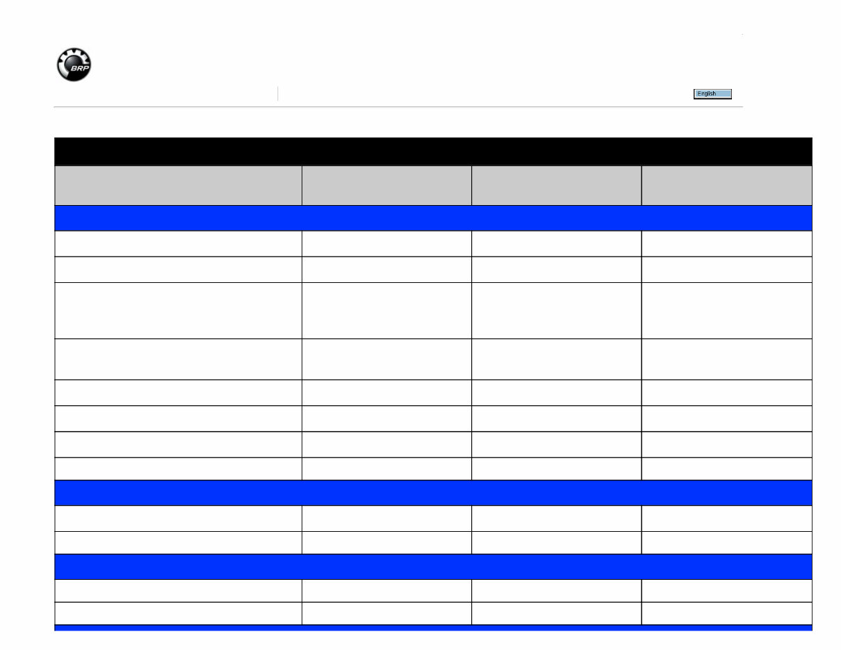
ATV 2013-2015 - Publication Directory 000047829_PUB51Y013_en PAC Information Detail: 2015 DESCRIPTION LANGUAGE PART NUMBER KNOWLEDGE CENTER ARTICLE NUMBER Shop Manual Outlander L - Outlander L MAX English 219100782 Not Available Outlander 6X6 (650-1000) English 219100786 Not Available Outlander-Xmr-MAX (500/650/800R/1000) Renegade (500/800R/1000) (Same as 2013) English 219100651 Not Available DS 70/ DS 90/ DS 90 X (same as 2008) English 219100278 Not Available DS 250 (same as 2006) English 219100236 Not Available DS 450/ 450 X (same as 2008) English 219100264 Not Available Outlander 400EFI (same as 2008) English 219100311 Not Available Flat Rate ATV 2015 Bilingual Not Available Not Available Wiring Diagram Booklet Rate This Article (Average Rating: No Rating)
Yellow Book Last Modified By: on 2014-07-14
SAFETY NOTICE SAFETY NOTICE This manual has been prepared as a guide to correctly service and repair 2008/2009 Outlander™ 400 EFI Series ATVs as describe in the model list in the INTRODUCTION. This edition was primarily published to be used by mechanical technicians who are already familiar with all service procedures relating to BRP products. Mechanical technicians should attend training courses given by B.R.P.T.I. Please note that the instructions will apply only if proper hand tools and special service tools are used. This shop manual uses technical terms which may be slightly different from the ones used in the PARTS CATALOG. It is understood that this manual may be translated into another language. In the event of any discrepan- cy, the English version shall prevail. The content depicts parts and/or procedures applicable to the particular product at time of writing. Ser- vice and Warranty Bulletins may be published to update the content of this manual. Make sure to read and understand these. It does not include dealer modifications, whether authorized or not by BRP, after manufacturing the product. In addition, the sole purpose of the illustrations throughout the manual, is to assist identification of the general configuration of the parts. They are not to be interpreted as technical drawings or exact replicas of the parts. The use of BRP parts is most strongly recommended when considering replacement of any component. Dealer and/or distributor assistance should be sought in case of doubt. The engines and the corresponding components identified in this document should not be utilized on product(s) other than those for which it was designed. WARNING Unless otherwise specified, engine should be turned OFF and cold for all maintenance and repair procedures. This manual emphasizes particular information denoted by the wording and symbols: WARNING Identifies an instruction which, if not followed, could cause serious personal injury including pos- sibility of death. CAUTION: Denotes an instruction which, if not followed, could severely damage vehicle compo- nents. NOTE: Indicates supplementary information needed to fully complete an instruction. Although the mere reading of such information does not eliminate the hazard, your understanding of the information will promote its correct use. Always use common shop safety practice. BRP disclaims liability for all damages and/or injuries resulting from the improper use of the contents. We strongly recommend that any services be carried out and/or verified by a highly skilled professional mechanic. It is understood that certain modifications may render use of the vehicle illegal under existing federal, provincial and state regulations. VIII vmr2008-113
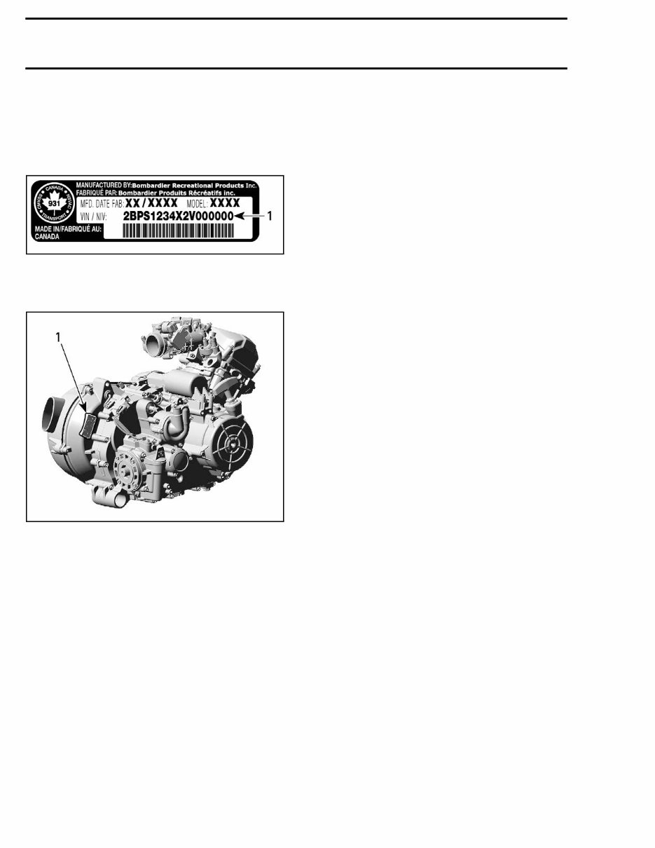
INTRODUCTION Vehicle Serial Number The Vehicle Identification Number (V.I.N.) is scribed on vehicle description decal. See above. It is also engraved on frame near vehicle descrip- tion decal. vmr2007-011-001_c 1. Vehicle serial number Engine Serial Number vmo2008-019-010_a 1. Engine serial number ENGINE EMISSIONS INFORMATION Manufacturer's Responsibility Manufacturers of engines must determine the ex- haust emission levels for each engine horsepower family and certify these engines with the United States of America ENVIRONMENTAL PROTEC- TION AGENCY (EPA). An emissions control infor- mation label, showing emission levels and engine specifications, must be placed on each vehicle at the time of manufacture. Dealer Responsibility When performing service on ATVs that carry an emissions control information label, adjustments must be kept within published factory specifica- tions. Replacement or repair of any emission related component must be executed in a manner that maintains emission levels within the prescribed certification standards. Dealers are not to modify the engine in any man- ner that would alter the horsepower or allow emis- sion levels to exceed their predetermined factory specifications. Exceptions include manufacturer's prescribed changes, such as altitude adjustments for exam- ple. Owner Responsibility The owner/operator is required to have engine maintenance performed to maintain emission levels within prescribed certification standards. The owner/operator is not to, and should not al- low anyone to modify the engine in any manner that would alter the horsepower or allow emis- sions levels to exceed their predetermined factory specifications. EPA Emission Regulations Some ATVs manufactured by BRP are certified to the EPA as conforming to the requirements of the regulations for the control of air pollution from new ATV engines. This certification is con- tingent on certain adjustments being set to factory standards. For this reason, the factory procedure for servicing the product must be strictly followed and, whenever practicable, returned to the origi- nal intent of the design. The responsibilities listed above are general and in no way a complete listing of the rules and regu- lations pertaining to the EPA requirements on ex- haust emissions for ATVs products. For more de- tailed information on this subject, you may contact the following locations: FOR ALL COURIER SERVICES: U.S. Environmental Protection Agency Office of Transportation and Air Quality 1310 L Street NW Washington D.C. 20005 REGULAR US POSTAL MAIL: 1200 Pennsylvania Ave. NW Mail Code 6403J Washington D.C. 20460 INTERNET: http://www.epa.gov/otaq/ E-MAIL: otaqpublicweb@epa.gov X vmr2008-113
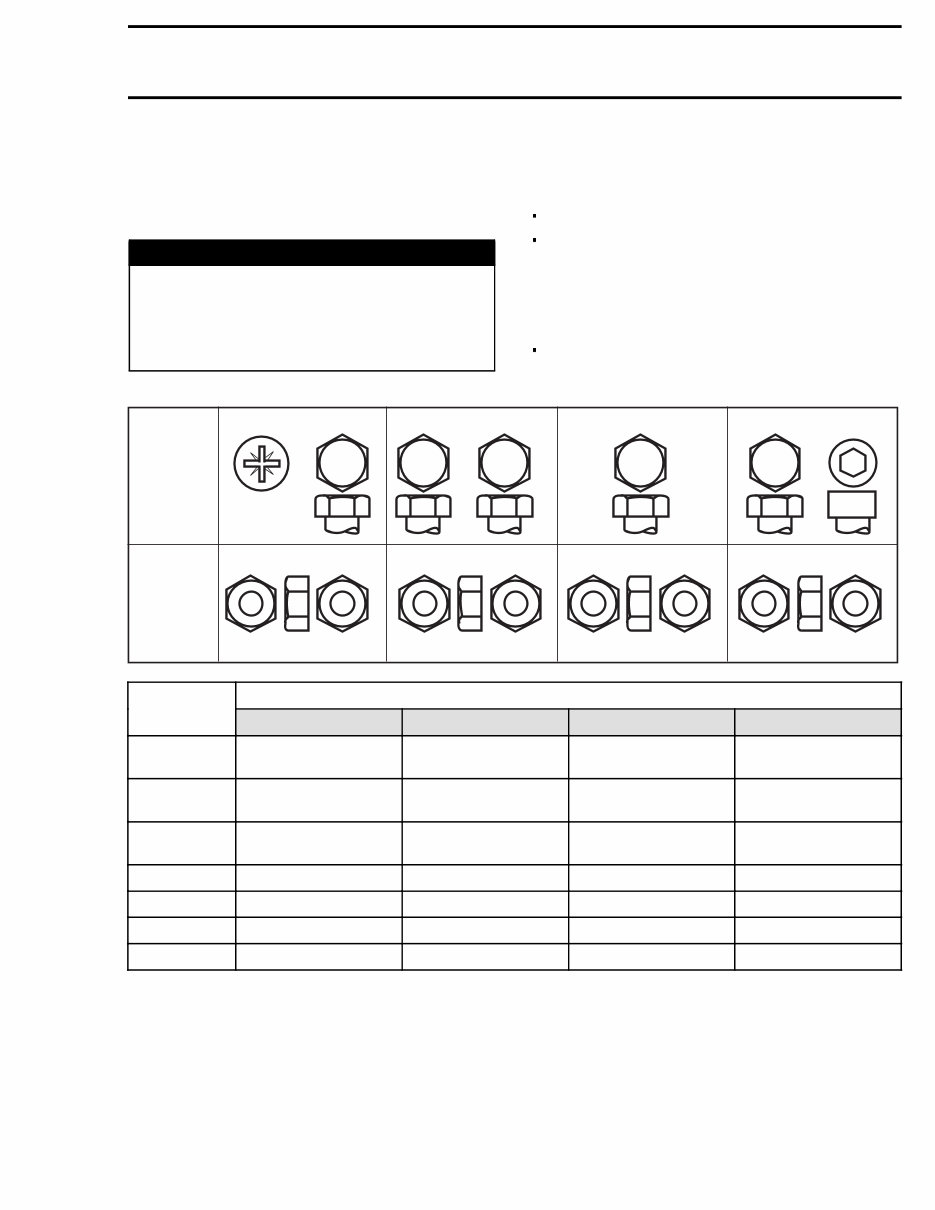
INTRODUCTION TIGHTENING TORQUE Tighten fasteners to torque mentioned in explod- ed views and/or text, When they are not specified, refer to following table. WARNING Torque wrench tightening specifications must strictly be adhered to. Locking devices (e.g.: locking tabs, elastic stop nuts, self-locking fasteners, cotter pins, etc.) must be replaced with new ones. In order to avoid a poor assembling, tighten screws, bolts or nuts in accordance with the following procedure: Manually screw all screws, bolts and/or nuts. Apply the half of the recommended torque value. CAUTION: Be sure to use proper tightening torque for the proper strength grade. NOTE: When possible, always apply torque on the nut. Torque at the recommended torque value. NOTE: Always torque screws, bolts and/or nuts in a crisscross sequence. FASTENER GRADE/TORQUE FASTENER SIZE 5.8 Grade 8.8 Grade 10.9 Grade 12.9 Grade M4 1.5 – 2 N•m (13 – 18 lbf•in) 2.5 – 3 N•m (22 – 27 lbf•in) 3.5 – 4 N•m (31 – 35 lbf•in) 4 – 5 N•m (35 – 44 lbf•in) M5 3 – 3.5 N•m (27 – 31 lbf•in) 4.5 – 5.5 N•m (40 – 47 lbf•in) 7 – 8.5 N•m (62 – 75 lbf•in) 8 – 10 N•m (71 – 89 lbf•in) M6 6.5 – 8.5 N•m (58 – 75 lbf•in) 8 – 12 N•m (71 – 106 lbf•in) 10.5 – 15 N•m (93 – 133 lbf•in) 16 N•m (142 lbf•in) M8 15 N•m (133 lbf•in) 25 N•m (18 lbf•ft) 32 N•m (23 lbf•ft) 40 N•m (30 lbf•ft) M10 29 N•m (21 lbf•ft) 48 N•m (35 lbf•ft) 61 N•m (45 lbf•ft) 73 N•m (53 lbf•ft) M12 52 N•m (38 lbf•ft) 85 N•m (63 lbf•ft) 105 N•m (77 lbf•ft) 128 N•m (94 lbf•ft) M14 85 N•m (63 lbf•ft) 135 N•m (100 lbf•ft) 170 N•m (125 lbf•ft) 200 N•m (148 lbf•ft) vmr2008-113 XI
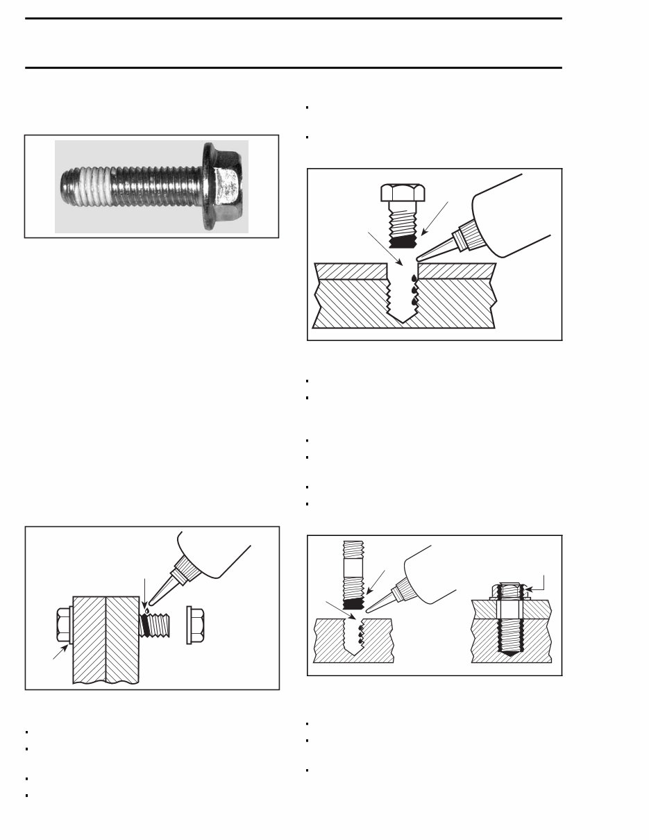
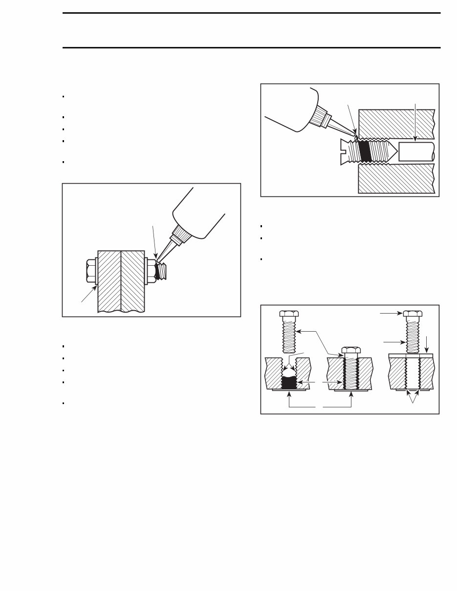
INTRODUCTION SELF-LOCKING FASTENERS PROCEDURE A00A6LA TYPICAL — SELF-LOCKING FASTENER The following describes the most common appli- cation procedures when working with self-locking fasteners. Use a metal brush or a tap to clean the hole prop- erly then use a solvent, let act during 30 minutes and wipe off. The solvent utilization is to ensure the adhesive works properly. LOCTITE ® APPLICATION PROCEDURE The following describes the most common ap- plication procedures when working with Loctite products. NOTE: Always use proper strength Loctite prod- uct as recommended in this shop manual. Threadlocker Uncovered Holes (bolts and nuts) 1. Apply here 2. Do not apply Clean threads (bolt and nut) with solvent. Apply Loctite Primer N (P/N 293 800 041) on threads and allow to dry. Choose proper strength Loctite threadlocker. Fit bolt in the hole. Apply a few drops of threadlocker at proposed tightened nut engagement area. Position nut and tighten as required. Blind Holes lmr2007-040-004_a 1. On threads 2. On threads and at the bottom of hole Clean threads (bolt and hole) with solvent. Apply Loctite Primer N (P/N 293 800 041) on threads (bolt and nut) and allow to dry for 30 sec- onds. Choose proper strength Loctite threadlocker. Apply several drops along the threaded hole and at the bottom of the hole. Apply several drops on bolt threads. Tighten as required. Stud in Blind Holes lmr2007-040-005_a 1. On threads 2. On threads and in the hole 3. Onto nut threads Clean threads (stud and hole) with solvent. Apply Loctite Primer N (P/N 293 800 041) on threads and allow to dry. Put 2 or 3 drops of proper strength Loctite threadlocker on female threads and in hole. XII vmr2008-113
INTRODUCTION NOTE: To avoid a hydro lock situation, do not apply too much Loctite. Apply several drops of proper strength Loctite on stud threads. Install stud. Install cover, etc. Apply drops of proper strength Loctite on uncov- ered threads. Tighten nuts as required. Pre-Assembled Parts A00A3OA 1 2 1. Apply here 2. Do not apply Clean bolts and nuts with solvent. Assemble components. Tighten nuts. Apply drops of proper strength Loctite on bolt/nut contact surfaces. Avoid touching metal with tip of flask. NOTE: For preventive maintenance on exist- ing equipment, retighten nuts and apply proper strength Loctite on bolt/nut contact surfaces. Adjusting Screw 1. Apply here 2. Plunger Adjust screw to proper setting. Apply drops of proper strength Loctite thread- locker on screw/body contact surfaces. Avoid touching metal with tip of flask. NOTE: If it is difficult to readjust, heat screw with a soldering iron (232°C (450°F)). Stripped Thread Repair 1. Release agent 2. Stripped threads 3. Form-A-Thread 4. Tapes 5. Cleaned bolt 6. Plate 7. New threads 8. Threadlocker Standard Thread Repair – Follow instructions on Loctite FORM-A- THREAD 81668 package. – If a plate is used to align bolt: a. Apply release agent on mating surfaces. b. Put waxed paper or similar film on the sur- faces. – Twist bolt when inserting it to improve thread conformation. NOTE: NOT intended for engine stud repairs. vmr2008-113 XIII
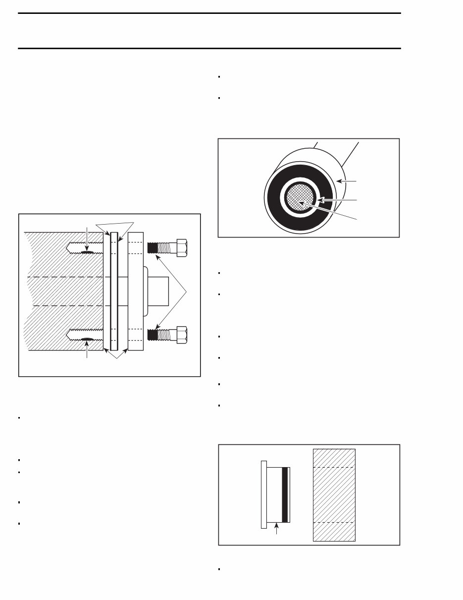
INTRODUCTION Repair of Small Holes/Fine Threads Option 1: Enlarge damaged hole, then follow STANDARD THREAD REPAIR procedure. Option 2: Apply FORM-A-THREAD on the screw and insert in damaged hole. Permanent Stud Installation (light duty) – Use a stud or thread on desired length. – DO NOT apply release agent on stud. – Doa STANDARD THREAD REPAIR. – Allow to cure for 30 minutes. – Assemble. Gasket Compound lmr2007-040-006_a 1. Proper strength Loctite 2. Loctite Primer N (P/N 293 800 041) and Loctite 518 (P/N 293 800 038) on both sides of gasket 3. Loctite Primer N only Remove old gasket and other contaminants with Loctite Chisel (gasket remover (P/N 413 708 500). Use a mechanical mean if necessary. NOTE: Avoid grinding. Clean both mating surfaces with solvent. Spray Loctite Primer N on both mating surfaces and on both sides of gasket. Allow to dry 1 or 2 minutes. Apply Loctite 518 (P/N 293 800 038) on both sides of gasket, using a clean applicator. Place gasket on mating surfaces and assemble immediately. NOTE: If the cover is bolted to blind holes (above), apply proper strength Loctite in the hole and on threads. Tighten. If holes are sunken, apply proper strength Loc- tite on bolt threads. Tighten as usual. Mounting on Shaft Mounting with a Press 1. Bearing 2. Proper strength Loctite 3. Shaft Clean shaft external part and element internal part. Apply a strip of proper strength Loctite on shaft circumference at insert or engagement point. NOTE: Retaining compound is always forced out when applied on shaft. DO NOT use antiseize Loctite or any similar product. No curing period is required. Mounting in Tandem Apply retaining compound on internal element bore. Continue to assemble as shown above. Case-In Components Metallic Gaskets 1. Proper strength Loctite Clean inner housing diameter and outer gasket diameter. XIV vmr2008-113
INTRODUCTION Spray housing and gasket with Loctite Primer N (P/N 293 800 041). Apply a strip of proper strength Loctite on lead- ing edge of outer metallic gasket diameter. NOTE: Any Loctite product can be used here. A low strength liquid is recommended as normal strength and gap are required. Install according to standard procedure. Wipe off surplus. Allow it to cure for 30 minutes. NOTE: Normally used on worn-out housings to prevent leaking or sliding. It is generally not necessary to remove gasket compound applied on outer gasket diameter. MANUAL INFORMATION The manual is divided into many major sections as you can see in the main table of contents at the beginning of the manual. Each section is divided in various subsections, and again, each subsection has one or more division. Illustrations and photos show the typical construc- tion of the different assemblies and, in all cases, may not reproduce the full detail or exact shape of the parts shown. However, they represent parts which have the same or a similar function. CAUTION: Most components of those vehicles are built with parts dimensioned in the metric system. Most fasteners are metric and must not be replaced by customary fasteners or vice-versa. Mismatched or incorrect fasteners could cause damage to the vehicle or possible personal injury. As many of the procedures in this manual are inter- related, we suggest, that before undertaking any task, you read and thoroughly understand the en- tire section or subsection in which the procedure is contained. A number of procedures throughout the book re- quire the use of special tools. Before commenc- ing any procedure, be sure that you have on hand all the tools required, or approved equivalents. The use of RIGHT and LEFT indications in the text, always refers to driving position (when sitting on vehicle). vmr2008-113 XV
Thank you for considering this comprehensive Service Repair Workshop Manual for the Can Am Outlander 400 Efi ATV from 2008 to 2015.
This manual encompasses all the necessary Service & Repair Procedures, making it an invaluable resource for both professional mechanics and DIY enthusiasts.
By utilizing this manual, you can significantly reduce expenses by performing your own repairs. It provides easy-to-follow, step-by-step instructions accompanied by illustrative pictures, covering all aspects of servicing and repairs.
Upon acquisition, this manual becomes your perpetual asset. You have the flexibility to print a single page, a specific chapter, or the entire manual. Additionally, it can be conveniently accessed on your tablet or smartphone.
All Models/Engines/Trim/Transmissions Types are comprehensively covered in this manual.
The high-quality Service Repair Workshop Manual encompasses all repair procedures from A to Z, ensuring that every repair and service process is thoroughly addressed.
This downloadable Manual is compatible with all PC & MAC Computers, tablets, and mobile phones. The only requisite software is Adobe Reader, which is typically pre-installed on most computers or can be obtained for free.
Upon payment via Visa, MasterCard, or PayPal, the manual will be promptly emailed to the address provided during checkout.
Customer Satisfaction is guaranteed with this comprehensive Service Repair Workshop Manual.
Recently Viewed
5,521,897Happy Clients
2,594,462eManuals
1,120,453Trusted Sellers
15Years in Business
Price:
Actual Price:
2008-2015 Can Am Outlander 400 Efi ATV Service & Repair Manual