

2000 Bombardier DS650 Service & Repair Manual
What's Included?
Fast Download Speeds
Online & Offline Access
Access PDF Contents & Bookmarks
Full Search Facility
Print one or all pages of your manual

Shop Manual
2000
DS 650

VMR2000_001_00_02A.FM I
SECTION SUBSECTION PAGE
SAFETY NOTICE ................................................................................................................................... III
INTRODUCTION .................................................................................................................................. IV
01 SERVICE TOOLS AND
SERVICE PRODUCTS
01 – Table of contents...................................................................... 01-01-1
02 – Service tools ............................................................................. 01-02-1
03 – Service products....................................................................... 01-03-1
02 MAINTENANCE 01 – Table of contents...................................................................... 02-01-1
02 – Maintenance chart.................................................................... 02-02-1
03 – Maintenance and lubrication .................................................... 02-03-1
04 – Storage and pre-season preparation......................................... 02-04-1
03 ENGINE 01 – Table of contents...................................................................... 03-01-1
02 – Removal and installation........................................................... 03-02-1
03 – Cooling system......................................................................... 03-03-1
04 – Magneto system ...................................................................... 03-04-1
05 – Cylinder and head ..................................................................... 03-05-1
06 – Crankshaft and balancer shaft .................................................. 03-06-1
07 – Lubrication system ................................................................... 03-07-1
08 – Clutch ....................................................................................... 03-08-1
09 – Transmission ............................................................................ 03-09-1
04 FUEL SYSTEM 01 – Table of contents...................................................................... 04-01-1
02 – Fuel circuit ................................................................................ 04-02-1
03 – Carburetor and fuel pump ........................................................ 04-03-1
04 – Air intake silencer ..................................................................... 04-04-1
05 ELECTRICAL 01 – Table of contents...................................................................... 05-01-1
02 – Overview .................................................................................. 05-02-1
03 – Charging system ...................................................................... 05-03-1
04 – Starting system ........................................................................ 05-04-1
05 – Ignition system......................................................................... 05-05-1
06 – Accessories .............................................................................. 05-06-1
06 DRIVE TRAIN 01 – Table of contents...................................................................... 06-01-1
02 – Drive chain................................................................................ 06-02-1
03 – Rear axle................................................................................... 06-03-1
07 STEERING/CONTROL
SYSTEMS
01 – Table of contents...................................................................... 07-01-1
02 – Steering/control systems ......................................................... 07-02-1
08 SUSPENSION 01 – Table of contents...................................................................... 08-01-1
02 – Front suspension ...................................................................... 08-02-1
03 – Rear suspension ....................................................................... 08-03-1
09 BRAKES 01 – Table of contents...................................................................... 09-01-1
02 – Hydraulic brakes ....................................................................... 09-02-1
10 BODY/FRAME 01 – Table of contents...................................................................... 10-01-1
02 – Body ......................................................................................... 10-02-1
03 – Frame ....................................................................................... 10-03-1
TABLE OF CONTENTS

II VMR2000_001_00_02A.FM
11 TECHNICAL DATA 01 – SI metric information guide...................................................... 11-01-1
02 – Engine and vehicle ................................................................... 11-02-1
12 WIRING DIAGRAM 01 – Wiring diagram......................................................................... 12-01-1
SECTION SUBSECTION PAGE
TABLE OF CONTENTS
IV VMR2000_001_00_02A.FM
INTRODUCTION
This Shop Manual covers the following Bombar-
dier made 2000 ATV:
Model
1. Model number
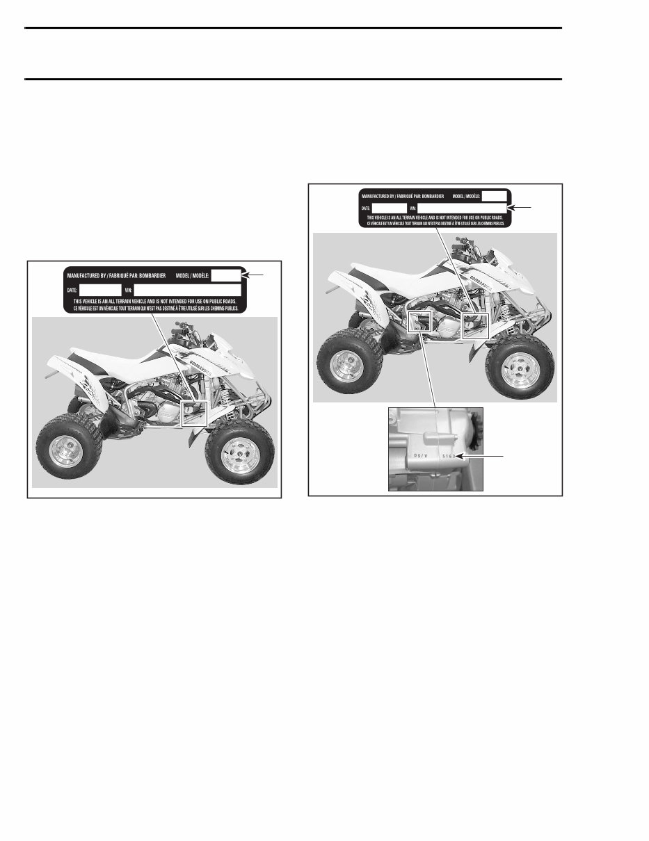
VEHICLE AND ENGINE SERIAL
NUMBER LOCATION
1. Vehicle
2. Engine
DS* 650......................................................7404
*Trademark of Bombardier Inc.
1
V02A0PA
1
2
V02A0QA
INTRODUCTION

VMR2000_001_00_02A.FM V
Serial Number Meaning
10 11 12 13 14 15 16 17 9 8 7 6 5 4 3 2 1
SECTION 1 SECTION 2 SECTION 3 SECTION 4
3 2 1
SECTION 1
Class
Make
Manufacturer
8 7 6 5 4
SECTION 2
Factory use
Engine type II
Engine type I
Product line
Type of drive
9
SECTION 3
Check digit
10 11 12 13 14 15 16 17
SECTION 4
Number sequentially assigned by the manufacturer
in the production process
Plant of manufacture
Model year
V01A0PS
INTRODUCTION

VI VMR2000_001_00_02A.FM
ARRANGEMENT OF THE
MANUAL
The manual is divided into 12 major sections:
Each section is divided in various subsections, and
again, each subsection has one or more division.
LIST OF ABBREVIATIONS USED
IN THIS MANUAL
01 SERVICE TOOLS AND SERVICE PRODUCTS
02 MAINTENANCE
03 ENGINE
04 FUEL SYSTEM
05 ELECTRICAL
06 DRIVE TRAIN
07 STEERING/CONTROL SYSTEMS
08 SUSPENSION
09 BRAKES
10 BODY/FRAME
11 TECHNICAL DATA
12 WIRING DIAGRAM
A ampere
amp ampere
A•h ampere-hour
AC alternate current
BDC bottom dead center
BTDC before top dead center
°C degree Celsius
cm centimeter
cm² square centimeter
cm³ cubic centimeter
DC direct current
°F degree Fahrenheit
fl. oz fluid ounce
ft foot
GRD ground
hal. halogen
I.D. inside diameter
IDI induction discharge ignition
imp. oz imperial ounce
in inch
in² square inch
in³ cubic inch
k kilo (thousand)
kg kilogram
km/h kilometer per hour
kPa kilo pascal
L liter
lb pound
lbf pound (force)
lbf/in² pound per square inch
LH left hand
m meter
MAG magneto
Max. maximum
Min. minimum
mL milliliter
mm millimeter
MPEM multi-purpose electronic module
MPH mile per hour
N newton
N.A. not applicable
no. number
00.0 continuity
0.L overload (open circuit)
O.D. outside diameter
OPT optional
oz ounce
P/N part number
PSI pound per square inch
PTO power take off
RPM revolution per minute
Sp. Gr. specific gravity
TDC top dead center
U.S. oz ounce (United States)
V volt
Vac volt (alternative current)
INTRODUCTION
VMR2000_001_00_02A.FM VII
Section 03 ENGINE
Subsection 05 (CYLINDER AND HEAD)
VMR2000 007 03 05A FM 03 05 1
CYLINDER AND HEAD
CYLINDER AND HEAD
9
12
4
8
21
22
23
27
V02C0ES
10 Nm
(89 lbfin)
10 Nm
(89 lbfin)
33 Nm
(24 lbfft)
10 Nm
(89 lbfin)
Loctite 243
10 Nm
(89 lbfin)
10 Nm
(89 lbfin)
60 Nm
(44 lbfft)
Engine oil
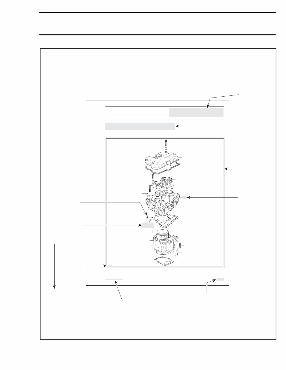
Page heading
indicates section
and subsection
detailed.
Bold face number
indicates special
procedure
concerning this
part.
Tightening torque
nearby fastener. In this
case, nut must be
torqued to
10 Nm or 89 lbfin.
This Shop Manual uses technical terms wich may be
slightly different from the ones in the parts catalog.
Exploded view
assists you in
identifying parts and
related positions.
TYPICAL PAGE
V02A0TS
Illustration
number for
publishing
process.
Subsection title
indicates
beginning of the
subsection.
Drop represents a
liquid product to
be applied to
a surface.
Page numbering system:
03: ENGINE section
05: CYLINDER AND HEAD
subsection
1: First page of this subsection
CAUTION: Pay attention to
torque specifications. Some
of these are in lbfft instead
of lbf in. Use appropriate
torque wrench.
Document
number for
publishing
process.
INTRODUCTION

VIII VMR2000_001_00_02A.FM
2
V02C18A 5 4 1 3
V02C19A
1 V02C05A
Call-out
Section 03 ENGINE
Subsection 02 (REMOVAL AND INSTALLATION)
VMR2000 004 03 02 FM 03 02 3
footrest (refer to BODY 10-02)
engine pinion no. 2 (refer to Engine Pinion sec-
tion)
RH SIDE OF ENGINE
1 Exhaust pipes
2 Radiator inlet hose
3 Oil line
4 Brake pedal
5 Footrest
carburetor and carburetor adaptor (refer to CAR-
BURETOR AND AIR INTAKE SILENCER 04-03)
gearshift pedal no. 9
Unscrew neutral switch connector
Removal
Remove the upper support bracket no. 10 com-
pletely
Install engine lifting tool (P/N 529 035 610) then,
install a hoist
Remove:
upper engine support bolt no. 11
lower bolts no. 12 retaining the engine support
no. 13 on either side, then, remove supports
front lower mounting bolt no. 14
rear lower mounting bolt no. 15
rear upper mounting bolt no. 16
Remove engine from vehicle
Installation
For installation, reverse the removal procedure,
paying attention to the following details
Reattach cables, hoses, wiring harness, etc
Adjust clutch cable
Bleed rear brake
Before to start the engine, remove oil filter
Unfasten pressure bleeding screw
BEHIND OIL FILTER
1 Bleeding screw
Unscrew and remove one spark plug
Turn engine using starter until oil emerges in filter
chamber
Tighten pressure bleeding screw
Install oil filter
This operation activated the oil pump Check if ve-
hicle runs correctly
2
V02C18A 5 4 1 3
V02C19A
1 V02C05A
Call-out
TYPICAL PAGE
Subtitle indicates
main procedure
to be carried out.
Reference to look
up a certain section
and subsection.
In this case it
concerns
carburetor and air
intake silencer.
Bold face number
following part name
refers to exploded
view at beginning of
subsection.
Call outs for
above illustration.
V02A0US
INTRODUCTION
VMR2000_001_00_02A.FM IX
GENERAL INFORMATION
The information and component/system descrip-
tions contained in this manual are correct at time
of publication. Bombardier however, maintains a
policy of continuous improvement of its products
without imposing upon itself any obligation to in-
stall them on products previously manufactured.
Due to late changes, it may have some differences
between the manufactured product and the descrip-
tion and/or specifications in this document.
Bombardier reserves the right at any time to dis-
continue or change specifications, designs, fea-
tures, models or equipment without incurring ob-
ligation.
ILLUSTRATIONS AND
PROCEDURES
Illustrations and photos show the typical construc-
tion of the different assemblies and, in all cases,
may not reproduce the full detail or exact shape of
the parts shown, however, they represent parts
which have the same or a similar function.
CAUTION: Most components of those vehicles
are built with parts dimensioned in the metric
system. Most fasteners are metric and must
not be replaced by customary fasteners or vice-
versa. Mismatched or incorrect fasteners could
cause damage to the vehicle or possible per-
sonal injury.
As many of the procedures in this manual are in-
terrelated, we suggest, that before undertaking
any task, you read and thoroughly understand the
entire section or subsection in which the proce-
dure is contained.
A number of procedures throughout the book re-
quire the use of special tools. Before commencing
any procedure, be sure that you have on hand all
the tools required, or approved equivalents.
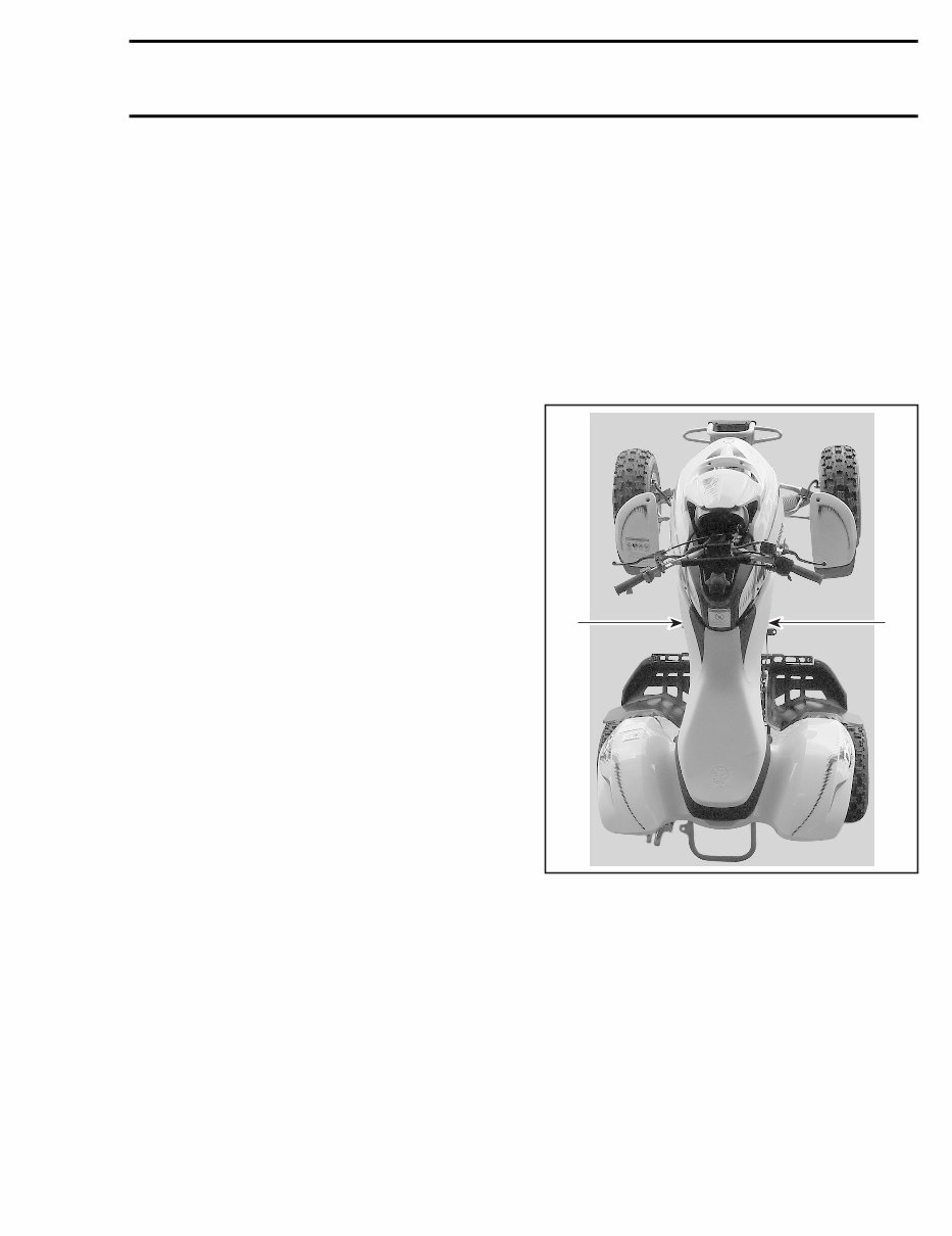
The use of RIGHT and LEFT indications in the text,
always refers to driving position (when sitting on
vehicle).
1. Left
2. Right
V02L02A
2 1
INTRODUCTION
You're Reading a Preview
What's Included?
Fast Download Speeds
Online & Offline Access
Access PDF Contents & Bookmarks
Full Search Facility
Print one or all pages of your manual
$31.99
$41.99
Viewed 46 Times Today


Secure transaction
What's Included?
Fast Download Speeds
Online & Offline Access
Access PDF Contents & Bookmarks
Full Search Facility
Print one or all pages of your manual
$31.99
$41.99
Get your hands on the comprehensive repair manual for the 2000 Bombardier DS650 ATV. This manual covers everything from complete tear down and rebuild to torque specs, maintenance, troubleshooting, and more. With 172 pages, it includes pictures and part diagrams to assist you every step of the way.
This manual features clickable chapters and is searchable, making it effortless to locate the information you need. There are no restrictions on printing or saving/burning to disc, providing you with the flexibility to use the manual as you prefer.
- Main jet
- Primary reduction gear
- Wheel
- Brakes
- Tank
- Plate
- Carburetor
- Reverse
- Viscosity
- Hydraulic
- Size
- Crank
- Tires
- Body
- Problem
- Cover
- Error codes
- Cam
- Bogey
- Rectifier
- Lights
- Side
- Tire
- Ignition
- Stroke
- Guides
- Installation
- Lubrication
- Camshaft
- Shaft
- Troubleshoot
- Handle
- Axle
- Skis
- Clutch
- Performance
- Rotors
- Forks
- Fix
- Cables
- Valves
- Coil
- Storage
- Front
- Online
- Hull
- Brake
- Carb
- Tork
- Charging
- Connecting rod
- Rotor
- Guide
- Mixture screw
- Light
- PGM-FI
- Exhaust
- Width
- Start
- Drive
- Triple
- Rebuild
- Instruction
- Boot
- Magneto
- EFI
- Boots
- Valve clearance
- Charge
- Swinger
- Gas
- Flush
- Four
- Rear
- Displacement
- Cylinder
- Chart
- Fuel
- Weight
- Pilot jet
- Illustration
- Which engine oil
- Drive shaft
- Switches
- Diagram
- Troubleshooting
- Bore
- Switch
- Switchs
- No spark
- Change coolant
- Idle
- Struts
- Panels
- Information
- Battery
- Clutch
- Tree
- System
- Fuel injection
- Error code
- Bar
- Fuel pump
- Regulator
- Ski
- Conrod
- Crankshaft
- Motor
- Schematic
- Strut
- Pump
- Instructions
- Thrust plate
- Muffler
- Swingarm
- PSI
- Data
- Piston
- Reference
- Trees
- Plastic
- Electric
- Length
- Rod
- Bars
- Problems
- Kicker
- Schedule
- Cams
- Track
- Speed
- Spring
- Shop
- DIY
- Line
- Kickstart
- Throttle cable
- Fender
- Parts
- Starter
- Jug
- Coolant
- Gearshift
- Torque specs
- Oversize
- Intake
- Plastics
- Adjust
- Plug
- Air
- Specs
- Radiator
- Starting
- Operation
- Carburettor
- Install
- Specifications
- Fix
- Cooler
- Transmission
- Fluid
- Overhaul
- Trouble
- Head
- Seat
- Oversized
- Electronic
- Slow jet
- Over
- Drive train
- Flywheel
- Stator
- Compression ratio
- Able
- Propulsion system
- Carboretor
- Fuse
- Kick
- Suspension
- Fenders
- Workshop
- Jet pump
- Pads
- Frame
- Linkage
- Steering


