

CLUB CAR GOLF CART KF82 Engine FACTORY Service Repair Manual
What's Included?
Fast Download Speeds
Online & Offline Access
Access PDF Contents & Bookmarks
Full Search Facility
Print one or all pages of your manual
KF82 KMOO-KF150
4-stroke air-cooled gasoline engine
WORKSHOP MANOU

INTRODUCTION
Kawasaki 4-stroke gasoline engine models, KF82, KF100 and KF150 are of
the same basic design utilizing a cast iron cylinder, a precision die cast alu-
minum alloy crankcase and side cover, and heavy duty ball bearings mounted
on crankshaft and counter balance shaft.
Other standard features of this series include;
• Electronic Ignition System
The KF100 and KF150 are provided with the contact breaker ignition
system type as an option.
• Automatic Spark Advance
• Electric Starter
The KF150 is equipped with the electric starter as standard. The KF82
and KF100 are provided that as an option.
Each model is available in two types.
One is "D" type which uses an extended crankshaft for power take-off and
other is "G" type which is a 2 to 1 gear reduction model utilizing an extend-
ed camshaft for power take-off. The procedures for assembly, disassembly
and adjustment for all these models are almost identical.
All rights reserved. No part of this publication may be reproduced, stored
in a retrieval system, or transmitted in any form or by any means, electronic
mechanical photocopying, recording or otherwise, without the prior written
permission of Engine Division/Kawasaki Heavy Industries, Ltd. No liability
can be accepted for any inaccuracies or omissions in this publication, al-
though every possible care has been taken to make it as complete and ac-
curate as possible. All procedures and specifications subject to change with-
out prior notice or obligation. Illustrations in this publication are intended
for reference use only and may not depict actual model component parts.
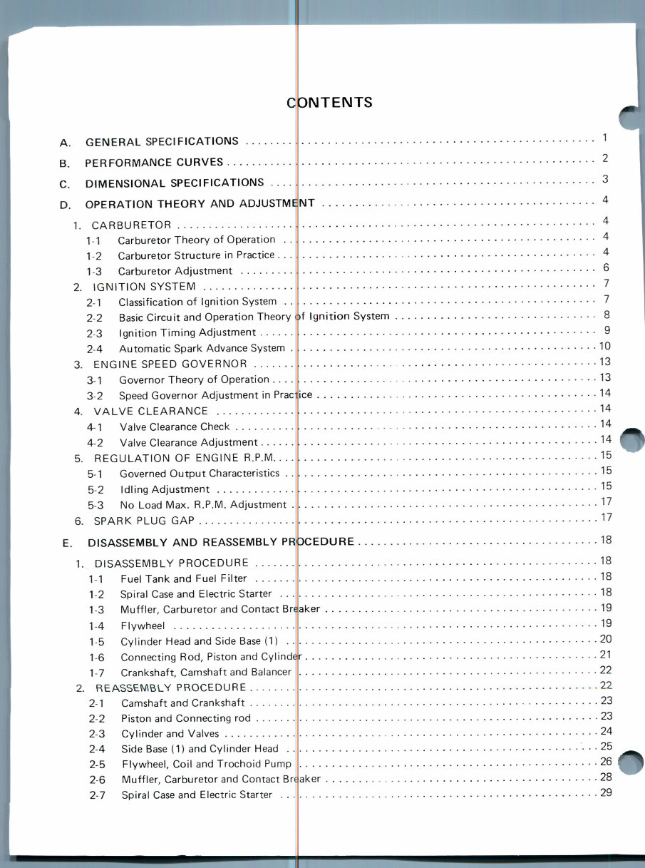
C3NTENTS
A. GENERAL SPECIFICATIONS
B. PERFORMANCE CURVES
C. DIMENSIONAL SPECIFICATIONS
D. OPERATION THEORY AND ADJUSTM
1. CARBURETOR
1-1 Carburetor Theory of Operation
1-2 Carburetor Structure in Practice .
1-3 Carburetor Adjustment
2. IGNITION SYSTEM
2-1 Classification of Ignition System
2-2 Basic Circuit and Operation Theory
2-3 Ignition Timing Adjustment ....
2-4 Automatic Spark Advance System
3. ENGINE SPEED GOVERNOR
3-1 Governor Theory of Operation ..
3-2 Speed Governor Adjustment in Prac
4. VALVE CLEARANCE
4-1 Valve Clearance Check
4-2 Valve Clearance Adjustment
5. REGULATION OF ENGINE R.P.M. ..
5-1 Governed Output Characteristics .
5-2 Idling Adjustment
5-3 No Load Max. R.P.M. Adjustment
6. SPARK PLUG GAP .
E. DISASSEMBLY AND REASSEMBLY PR
1. DISASSEMBLY PROCEDURE
1-1 Fuel Tank and Fuel Filter
1-2 Spiral Case and Electric Starter .
1-3 Muffler, Carburetor and Contact Br
1-4 Flywheel
1-5 Cylinder Head and Side Base (1) .
1-6 Connecting Rod, Piston and Cylind<
1-7 Crankshaft, Camshaft and Balancer
2. REASSEMBLY PROCEDURE
2-1 Camshaft and Crankshaft
2-2 Piston and Connecting rod
2-3 Cylinder and Valves
2-4 Side Base (1) and Cylinder Head ..
2-5 Flywheel, Coil and Trochoid Pump
2-6 Muffler, Carburetor and Contact Br
2-7 Spiral Case and Electric Starter . . .
NT
f Ignition System 8
ce
10
13
13
14
14
14
14
15
15
15
17
17
ker
)CEDURE 18
18
18
18
19
. . 19
20
21
22
22
23
23
24
25
26
28
.29
ker
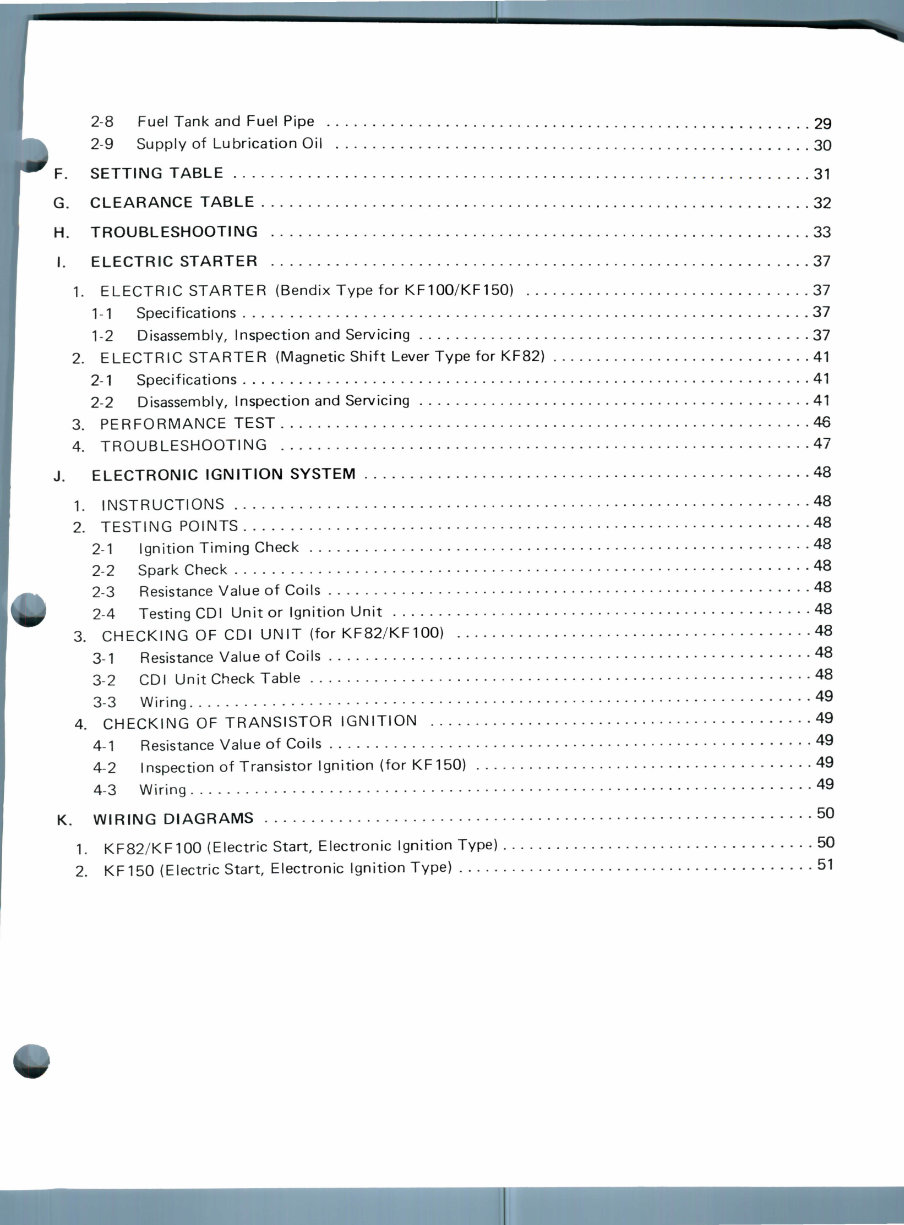
2-8 Fuel Tank and Fuel Pipe 29
2-9 Supply of Lubrication Oil 30
F. SETTING TABLE 31
G. CLEARANCE TABLE 32
H. TROUBLESHOOTING 33
I. ELECTRIC STARTER 37
1. ELECTRIC STARTER (Bendix Type for KF100/KF150) 37
1-1 Specifications 37
1-2 Disassembly, Inspection and Servicing 37
2. ELECTRIC STARTER (Magnetic Shift Lever Type for KF82) 41
2-1 Specifications 41
2-2 Disassembly, Inspection and Servicing 41
3. PERFORMANCE TEST 46
4. TROUBLESHOOTING 47
J. ELECTRONIC IGNITION SYSTEM 48
1. INSTRUCTIONS 48
2. TESTING POINTS 48
2-1 Ignition Timing Check 48
2-2 Spark Check 48
2-3 Resistance Value of Coils 48
2-4 Testing GDI Unit or Ignition Unit 48
3. CHECKING OF GDI UNIT (for KF82/KF100) 48
3-1 Resistance Value of Coils 48
3-2 GDI Unit Check Table 48
3-3 Wiring 49
4. CHECKING OF TRANSISTOR IGNITION 49
4-1 Resistance Value of Coils 49
4-2 Inspection of Transistor Ignition (for KF150) 49
4-3 Wiring 49
K. WIRING DIAGRAMS 50
1. KF82/KF100 (Electric Start, Electronic Ignition Type) 50
2. KF150 (Electric Start, Electronic Ignition Type) 51

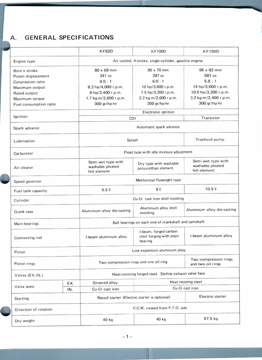
A. GENERAL SPECIFICATIONS
Engine type
Bore x stroke
Piston displacement
Conpression ratio
Maximum output
Rated output
Maximum torque
Fuel consumption ratio
Ignition
Spark advance
Lubrication
Carburetor
Air cleaner
Speed governor
Fuel tank capacity
Cylinder
Crank case
Main bearings
Connecting rod
Piston
Piston rings
Valves (EX. IN.)
EX.
IN.
Starting
Direction of rotation
Dry weight
KF82D
KF100D
KF150D
Air cooled, 4-stroke, single cylinder, gasoline engine
80 x 68 mm
341 cc
6.0 : 1
8.2 hp/4,000 r.p.m.
6 hp/3,400 r.p.m.
1.7 kg-m/2,600 r.p.m.
300 gr/hp-hr
85 x 70 mm
397 cc
6.0 : 1
10 hp/3,600 r.p.m.
7.5 hp/3,200 r.p.m.
2.2 kg-m/2,600 r.p.m.
300 gr/hp-hr
95 x 82 mm
581 cc
5.8 : 1
14 hp/3,600 r.p.m.
10.5 hp/3,200 r.p.m.
3.2 kg-m/2,400 r.p.m.
300 gr/hp-hr
Electronic ignition
GDI Transistor
Automatic spark advance
Splash Trochoid pump
Float type with idle mixture adjustment
Semi wet type with
washable pleated
felt element
Dry type with washable
polyurethan element
Semi wet type with
washable pleated
felt element
Mechanical flyweight type
6.5 £ 82 10.52
Cu-Cr cast iron shell molding
Aluminum alloy die-casting
Aluminum alloy shell
molding
Aluminum alloy die-casting
Ball bearings on each end of crankshaft and camshaft
I-beam aluminum alloy
I-beam, forged carbon
steel forging with plain
bearing
I-beam aluminum alloy
Low expansion aluminum alloy
Two compression rings and one oil ring
Two compression rings
and two oil rings
Heat-resisting forged steel. Stellite exhaust valve face
Sintered alloy
Cu-Cr cast iron
Heat resisting steel
Cu-Cr cast iron
Recoil starter (Electric starter is optional) Electric starter
C.C.W. viewed from P.T.O. side
40 kg 40 kg 67.5 kg
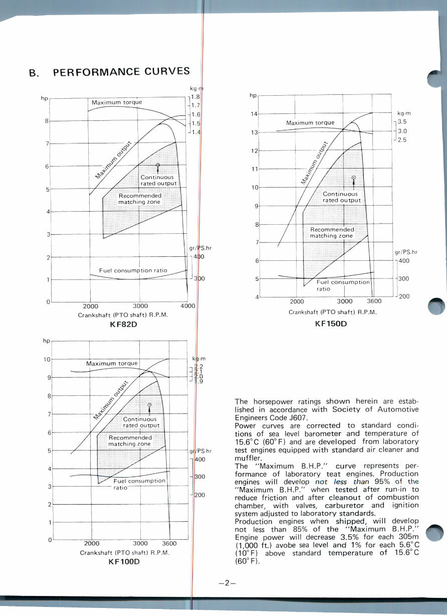
B. PERFORMANCE CURVES
Maximum torque
Continuous
rated output
Recommended
matching zone
Fuel consumption ratio
2000 3000
Crankshaft (PTO shaft) R.P.M.
KF82D
Maximum torque
Continuous
rated output
Recommended
matching zone
2000 3000 3600
Crankshaft (PTO shaft) R.P.M.
KF100D
Recommended
matching zone
gr/PS.hr
400
2000 3000 3600
Crankshaft (PTO shaft) R.P.M.
KF150D
The horsepower ratings shown herein are estab-
lished in accordance with Society of Automotive
Engineers Code J607.
Power curves are corrected to standard condi-
tions of sea level barometer and temperature of
15.6°C (60° F) and are developed from laboratory
test engines equipped with standard air cleaner and
muffler.
The "Maximum B.H.P." curve represents per-
formance of laboratory teat engines. Production
engines will develop not /ess than 95% of the
"Maximum B.H.P." when tested after run-in to
reduce friction and after cleanout of combustion
chamber, with valves, carburetor and ignition
system adjusted to laboratory standards.
Production engines when shipped, will develop
not less than 85% of the "Maximum B.H.P."
Engine power will decrease 3.5% for each 305m
(1,000 ft.) avobe sea level and 1% for each 5.6°C
(10°F) above standard temperature of 15.6°C
(60° F).
-2-
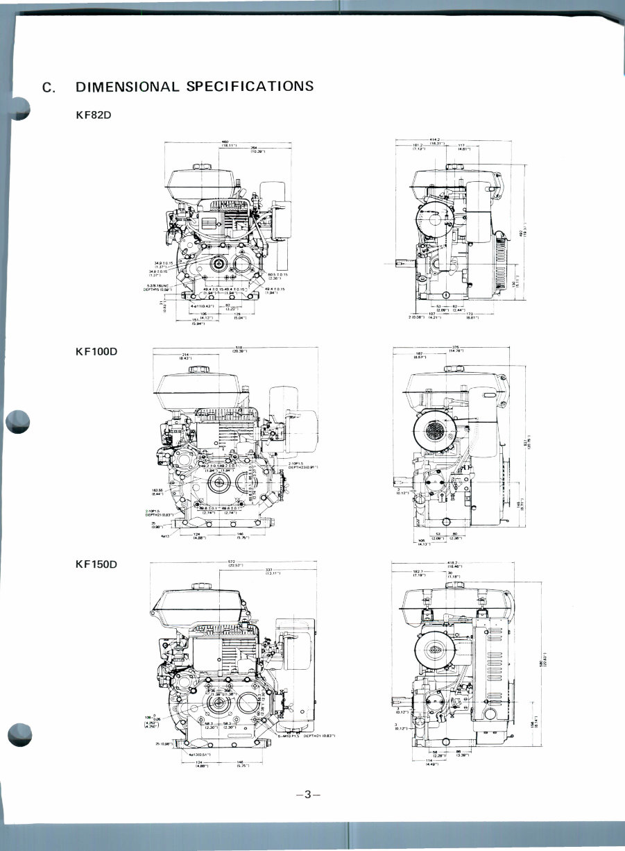
C. DIMENSIONAL SPECIFICATIONS
KF82D
KF100D
KF150D
-3-
D. OPERATION THEORY AND
ADJUSTMEI
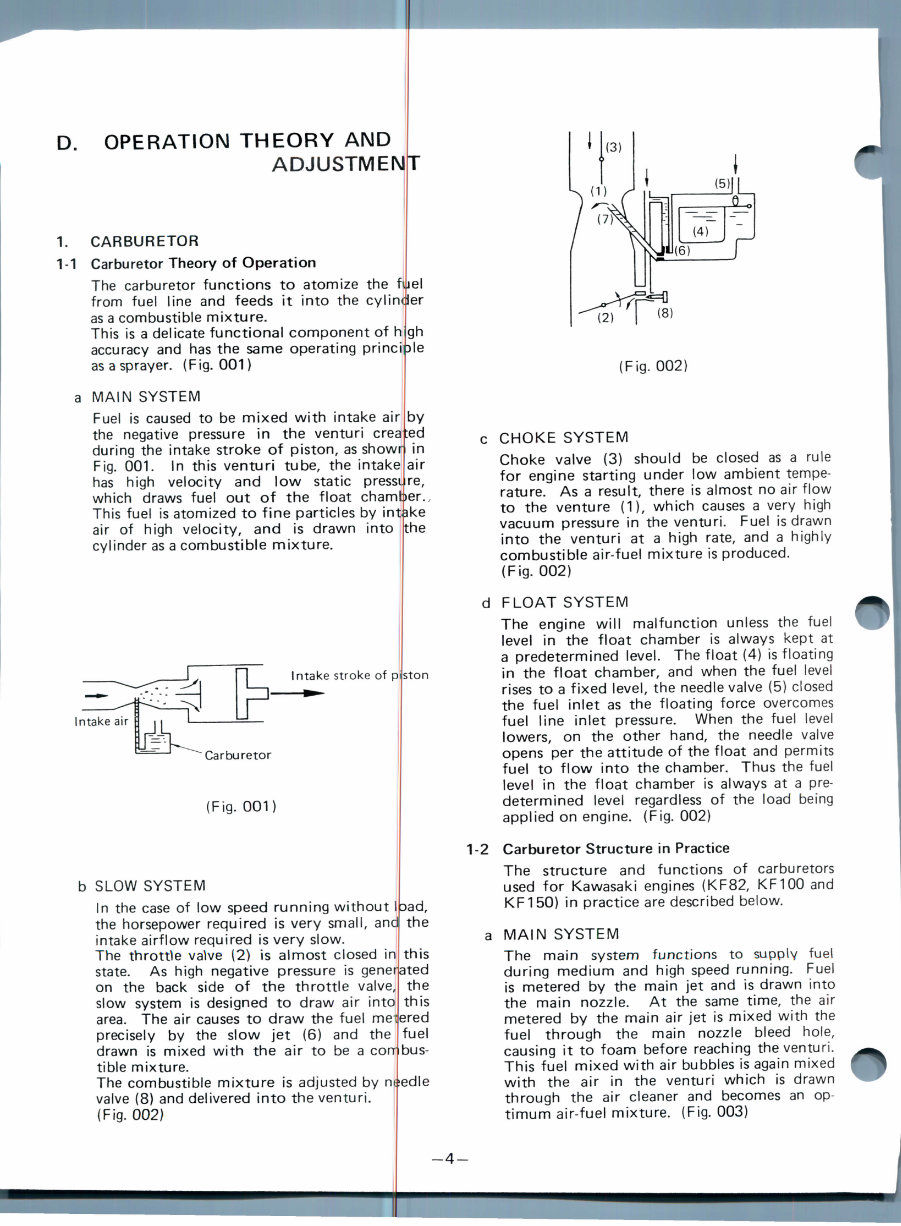
1. CARBURETOR
1-1 Carburetor Theory of Operation
The carburetor functions to atomize the filiel
from fuel line and feeds it into the cylinder
as a combustible mixture.
This is a delicate functional component of high
accuracy and has the same operating principle
as a sprayer. (Fig. 001)
a MAIN SYSTEM
Fuel is caused to be mixed with intake air
the negative pressure in the venturi crea
during the intake stroke of piston, as showr
Fig. 001. In this venturi tube, the intake
has high velocity and low static pressi
by
ted
in
air
re,
which draws fuel out of the float chamber.
This fuel is atomized to fine particles by intake
air of high velocity, and is drawn into (the
cylinder as a combustible mixture.
Intake stroke of p
Carburetor
(Fig. 001)
b SLOW SYSTEM
In the case of low speed running without
the horsepower required is very small, ani
intake airflow required is very slow.
The throttle vaWe (2) is almost closed in
ston
the
this
state. As high negative pressure is generated
on the back side of the throttle valve, the
slow system is designed to draw air into this
area. The air causes to draw the fuel melered
precisely by the slow jet (6) and the I fuel
drawn is mixed with the air to be a combus-
tible mixture.
The combustible mixture is adjusted by needle
valve (8) and delivered into the venturi.
(Fig. 002)
(Fig. 002)
c CHOKE SYSTEM
Choke valve (3) should be closed as a rule
for engine starting under low ambient tempe-
rature. As a result, there is almost no air flow
to the venture (1), which causes a very high
vacuum pressure in the venturi. Fuel is drawn
into the venturi at a high rate, and a highly
combustible air-fuel mixture is produced.
(Fig. 002)
d FLOAT SYSTEM
The engine will malfunction unless the fuel
level in the float chamber is always kept at
a predetermined level. The float (4) is floating
in the float chamber, and when the fuel level
rises to a fixed level, the needle valve (5) closed
the fuel inlet as the floating force overcomes
fuel line inlet pressure. When the fuel level
lowers, on the other hand, the needle valve
opens per the attitude of the float and permits
fuel to flow into the chamber. Thus the fuel
level in the float chamber is always at a pre-
determined level regardless of the load being
applied on engine. (Fig. 002)
1-2 Carburetor Structure in Practice
The structure and functions of carburetors
used for Kawasaki engines (KF82, KF100 and
KF150) in practice are described below.
a MAIN SYSTEM
The main system functions to supply fuel
during medium and high speed running. Fuel
is metered by the main jet and is drawn into
the main nozzle. At the same time, the air
metered by the main air jet is mixed with the
fuel through the main nozzle bleed hole,
causing it to foam before reaching the venturi.
This fuel mixed with air bubbles is again mixed
with the air in the venturi which is drawn
through the air cleaner and becomes an op-
timum air-fuel mixture. (Fig. 003)
-4-
You're Reading a Preview
What's Included?
Fast Download Speeds
Online & Offline Access
Access PDF Contents & Bookmarks
Full Search Facility
Print one or all pages of your manual
$31.99
Viewed 51 Times Today


Secure transaction
What's Included?
Fast Download Speeds
Online & Offline Access
Access PDF Contents & Bookmarks
Full Search Facility
Print one or all pages of your manual
$31.99
The CLUB CAR GOLF CART KF82 FACTORY SERVICE REPAIR MANUAL is a comprehensive guide specifically designed for maintaining and repairing Kawasaki KF82, KF100, and KF150 engines. This manual offers detailed instructions for dismantling and fixing major components, accompanied by a wealth of illustrations and photos to facilitate easy comprehension. Whether you're a professional mechanic or a DIY enthusiast, this manual is an invaluable resource for all your repair needs.
Accessing this manual is quick and convenient, providing you with the essential information you need. You can securely complete your purchase using our trusted server, which accepts both credit card and PayPal payments.


