VOLVO B12B, Lorry and Bus Service and Repair Manual
What's Included?
Lifetime Access
Fast Download Speeds
Online & Offline Access
Access PDF Contents & Bookmarks
Full Search Facility
Print one or all pages of your manual
17102-2 Delivery service Note: As the illustrations in the service literature are used for several different engine and vehicle variants, certain details may differ from the variant you are working with. The essential information in the illustrations is, however, always correct. Special tools: 88890020, 88890075, 88890105, 9992976, 9996461, 9996926, 9998433, 9998435, 9998901 Checking fault codes 1 Perform VCADS Pro 17012-3 Fault codes, reading . 2 Delete inactive error codes. The error codes will be saved automatically on the job card. Do not disconnect diagnostic tool and connectors. The PC tool will be used at later check points. Check vehicle information 3 Retrieve the vehicle information with VCADS Pro 17034-3 Vehicle information, test 4 Check that the information read off agrees with the vehicle's printed VIC-card which is from the chassis factory. 5 Check the chassis ID, hardware (HW), software (SW), Dataset 1, Dataset 2, Parameters. Note: If the VIC card information and the information read with the PC tool from the bus do not correspond, contact Actions Service. Check the fault codes for air suspension 6 The fault code check is performed with VCADS Pro. 7 Check that the chassis number and label number on the control units correspond. Buses with articulated wagon have two control units. Use Diagnosis Interface 9998433 or 88890020. Check error codes. Check kneeling and air spring height. If necessary, adjust the setting for kneeling and ground clearance in accordance with 72876-3 Level sensors, test Special tools: 9998433, 88890020 Check fault codes for fifth wheel (only rear-engine articulated buses) 8 Check of error codes is performed with software Hübner that is available on VBC Remote. 9 Use Diagnosis Interface9998433 and Adapter 9998901. Special tools: 9998433, 9998901 10 Page 1 of 17 sb58946_node59 5/3/2016 http://localhost:9907/impact3/application/staticdb/lang/enGB/sb58946_node59.xhtm
Check error codes. Check of engine controls 11 Check that the accelerator is easy to operate and returns to its original position. Check retarder control 12 Check that the control steps are distinct and that the control remains in the set position. Check direction indicators, hazard warning lights and destination signs 13 Move the indicator lever. 14 Check that the direction indicators on the bus and the control lamps on the dashboard illuminate. 15 Turn the hazard warning lights on. Check all indicator lamps. The switch should flash at the same rate. 16 Check function of destination signs. Page 2 of 17 sb58946_node59 5/3/2016 http://localhost:9907/impact3/application/staticdb/lang/enGB/sb58946_node59.xhtm
Check of lighting and signal horn 17 Check: Interior lighting lighting in the passenger area instrument lighting lighting in the switches horn all external lighting including brake lights and main beam flash Check stop buttons 18 Check: stop button door opening button pram button disabled button door opening handle start panel in the engine compartment Check the windscreen and headlamp washers 19 Check that the windscreen and headlamp washers are working and that the jets are accurate. Check the windscreen wiper and headlamp wiper 20 Check that the windscreen wipers and headlamp wipers wipe clean and stop in the parking position. Check warning and indication lamps 21 Set the knob in drive mode. 22 Page 3 of 17 sb58946_node59 5/3/2016 http://localhost:9907/impact3/application/staticdb/lang/enGB/sb58946_node59.xhtm
Warning and indication lamps are tested with the lever on the right-hand side of the steering wheel and the instrument display. 23 Access the menu: Fault diagnosis / Instrument test / Control lamp test on the display. 24 Perform and read off the gauge test, display test and buzzer test. 25 Press Select (2) when Control lamp test is highlighted on the display. Warning and control lamps on the instrument are illuminated for approx. 10 seconds. To interrupt the test press Esc (1). Check telematics 26 Check that the telematics system is correctly connected. Page 4 of 17 sb58946_node59 5/3/2016 http://localhost:9907/impact3/application/staticdb/lang/enGB/sb58946_node59.xhtm
Close all doors. 1. Open the front door with the switch. 2. Symbol for "door open" must be shown in the driver display. 3. Check the audio system 27 Check: Radio and CD changer Loudspeaker Microphones That the radio code is available Check of seats 28 Check the functions of the driver's seat. 29 Check seat belts on all seats where appropriate. Check the door functions 30 Check keys, external and internal hatches, door locks, door alarms, pinch protection and central locking. Check of handicap equipment 31 Test equipment for disabled/access ramp function. Check the emergency equipment 32 Check that the following are available: 2 first-aid boxes • 1 fire extinguisher • Emergency hammer • Signs • Key ring with key label and spare key. • 33 Check the function of the roof hatches, these also work as emergency exits. Check of headlamps 34 Perform an external check. Note: Before the check is carried out, make sure there is air in the bellows. Page 5 of 17 sb58946_node59 5/3/2016 http://localhost:9907/impact3/application/staticdb/lang/enGB/sb58946_node59.xhtm
35 Check using the light settings instrument that the setting for full and dipped beam is correct. 36 Check the setting of any front fog lamps and spot lamps. 37 Adjust the lights if necessary. Check battery and battery box function 38 Warning Batteries contain strong, corrosive sulfuric acid. When handling batteries, always use protective goggles! 39 Check batteries using battery analyser 88890075. Note: Note the battery status in the report. Special tools: 88890075 40 Caution This chapter is only valid for conventional batteries. Never loosen the cell plugs on a sealed Maintenance-free battery. Electrolyte can not be added without damaging the encapsulation. 41 Page 6 of 17 sb58946_node59 5/3/2016 http://localhost:9907/impact3/application/staticdb/lang/enGB/sb58946_node59.xhtm
Check the level of the electrolyte in each cell. If present, the markings on the battery that show min/max level should be followed. Otherwise, the fluid level should be 18–28 mm above the lead plates. If you need to top up the fluid, only use distilled water. Danger Be careful not to splash when topping up the batteries. Always use protective goggles when handling batteries. The electrolyte is extremely corrosive. Caution Do not fill with too much battery water. The electrolyte may be forced up through the ventilation holes and cause serious rust corrosion. 42 Check that the battery attachments are not damaged and that the batteries are securely fastened. Note: Fasteners which are too tight can damage the batteries. 43 Caution Check that the cables are correctly insulated and properly positioned. 44 Check ground cable attachment. 45 Page 7 of 17 sb58946_node59 5/3/2016 http://localhost:9907/impact3/application/staticdb/lang/enGB/sb58946_node59.xhtm
Caution Check the supply cable from the battery to the starter motor for location and clamping. Check the coolant mixture 46 Warning The expansion tanks are roof-mounted on certain variants. Use an approved platform or step ladder. Exercise great caution during this check. Expansion tank cooling circuit engine. • Expansion tank cooling circuits for ESS/EM • 47 Recommended freezing point is minimum -24 °C. Check coolant using hydrometer 88890105. Check that all cocks for the heating system are open. Pressure test the system, see 26006-2 Cooling system, pressure test . Perform a visual check of cooling coils, heating elements and heaters. Special tools: 88890105 Page 8 of 17 sb58946_node59 5/3/2016 http://localhost:9907/impact3/application/staticdb/lang/enGB/sb58946_node59.xhtm
Check the oil levels and drive belts 48 Check engine oil level, hydraulic fluid and servo oil. 49 Check AC belt, alternator belts and drive belts. Check clamps and connections in the engine compartment from all hatches visually. Check the silencer installation visually. Check of air pressure in tyres 50 Pump the tyres, including the spare tyre, to the correct air pressure. 51 Check that none of the valve caps are missing. Check the wheel nuts 52 Check that all wheel nuts have the correct torque, 670 ± 30 Nm. Check that no wheel nut caps are missing. Note: Tighten the wheel nuts in the order shown in the figure. If inadequate torque is discovered on any of the wheel nuts then all wheel nuts must be loosened and retightened. For instructions, see Wheel installation . Specifications: 670 ± 30 Nm Check starter heater 53 Apply the parking brake. Check that the gear selector is in neutral. 54 Turn the key to the pre-heating position and check the starting heater. 55 Check that the control lamp for preheating illuminates. Check that preheating has started. When the engine is cold, preheating takes place for a certain number of seconds depending on coolant temperature. Following which, the lamp is switched off. This should take place within a few seconds on a warm engine. Page 9 of 17 sb58946_node59 5/3/2016 http://localhost:9907/impact3/application/staticdb/lang/enGB/sb58946_node59.xhtm
Get your hands on the VOLVO B12B, LORRY AND BUS SERVICE AND REPAIR MANUAL. These Auto Repair Manuals are a must-have for both professional mechanics and DIY enthusiasts. They provide comprehensive instructions and procedures for fixing problems in your vehicle, making immediate repairs a breeze.
With 20 years of experience in auto repair and body work, these manuals offer invaluable customer support over email, ensuring you fix your car right the first time. The durability of your vehicle is unquestionable, but constant use can cause deterioration. When this happens, you'll need to replace parts, and some are simple to mount without professional help.
A trusty repair manual not only saves you money but also lets you experience the fun of do-it-yourself projects. It contains technical data, diagrams, a complete list of car parts, and pictures. Even the most novice car mechanic can easily follow the step-by-step guides, thanks to the simple illustrations and drawings.
These manuals cover all models and all repairs A-Z, providing you with everything you need to maintain, service, diagnose, and repair your vehicle. They include complete step-by-step instructions, diagrams, illustrations, wiring schematics, and specifications to make the repair process a breeze.
Compatible with all versions of Windows and Mac, these manuals are printable and offer language support in English. They are also compatible with Adobe Reader and Win, which are available online for free.
Auto Repair Manuals save you time and provide all the necessary car information. You can enjoy browsing through the pages and learning how to repair different parts of your car, empowering you to handle even the simplest car repairs without relying on a mechanic. The printable pages allow you to take the manual with you into the garage or workshop, ensuring it stays clean and intact.
Don't miss out on these comprehensive repair manuals that put the power of car repair in your hands.
Maintenance
Engine
Control System
Mechanical
Fuel Service Specifications
Emission Control
Intake Exhaust Cooling
Lube
Ignition Starting Charging
Auto Transmission Clutch
Manual Transmission
Transfer Propeller Shaft
Drive Shaft
Differential
Axle Suspension
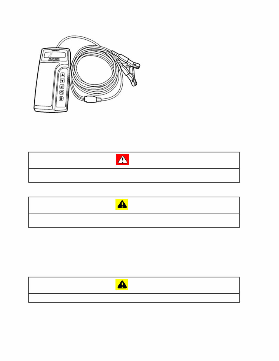
Tire & Wheel
Brake Control
Brake
Parking Brake
Steering Column
Power Steering
Air Condition
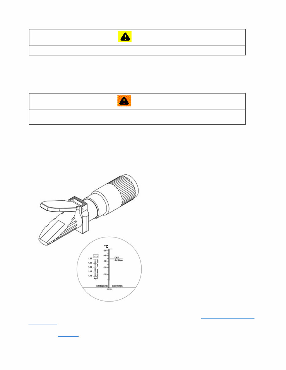
Suppl Restraint System
Seat Belt
Engine Immobilizer
Cruise Control
Wiper & Washer
Door Lock
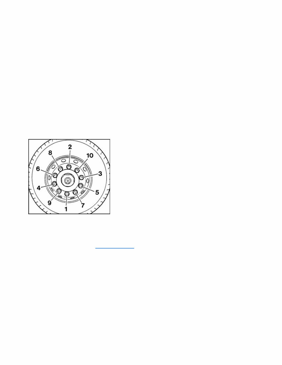
Meter Audio/Visual
Horn
Windshield/Glass Mirror
Instrument Panel
Seat
Engine Hood/ Door
Exterior & Interior
Electrical
Multiplex/ Can Communication
And much more...
Don't miss out on these comprehensive repair manuals that put the power of car repair in your hands.
Recently Viewed
5,521,897Happy Clients
2,594,462eManuals
1,120,453Trusted Sellers
15Years in Business
Price:
Actual Price:
VOLVO B12B, Lorry and Bus Service and Repair Manual