

Piper PA-23 Aztec Service & Repair Manual
What's Included?
Fast Download Speeds
Online & Offline Access
Access PDF Contents & Bookmarks
Full Search Facility
Print one or all pages of your manual
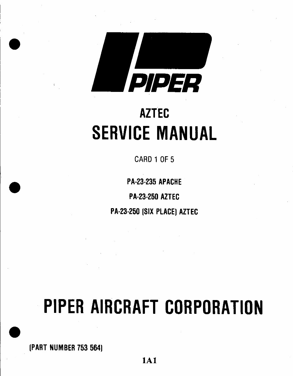
AZTEC
SERVICE
MANUAL
CARD 1 OF 5
PA-23-235 APACHE
PA-23-250 AZTEC
PA-23-250 (SIX PLACE) AZTEC
PIPER AIRCRAFT
CORPORATION
(PART NUMBER 753 564)
lAl
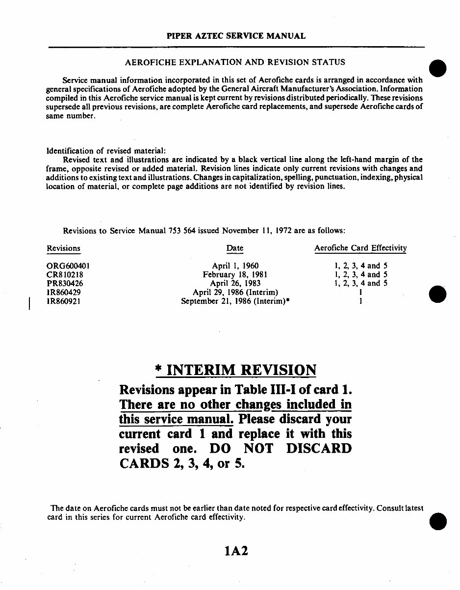
PIPER AZTEC SERVICE MANUAL
AEROFICHE EXPLANATION AND REVISION STATUS
Service manual information incorporated in this set of Aerofiche cards is arranged in accordance with
general specificationsof Aerofiche adopted by the General Aircraft Manufacturer's Association.Information
compiled in this Aerofiche servicemanual is kept current by revisions distributed periodically. Theserevisions
supersedeall previous revisions,are complete Aerofichecard replacements,and supersedeAerofiche cards of
same number.
Identification of revised material:
Revised text and illustrations are indicated by a black vertical line along the left-hand margin of the
frame, opposite revised or added material. Revisionlines indicate only current revisions with changes and
additions to existing text and illustrations.Changes in capitalization, spelling, punctuation, indexing, physical
location of material, or complete page additions are not identified by revision lines.
Revisions to Service Manual 753 564 issued November 11, 1972are as follows:
Revisions Date Aerofiche Card Effectivity
ORG600401
CR810218
PR830426
IR860429
IR860921
April 1, 1960
February 18, 1981
April 26, 1983
April 29, 1986(Interim)
September 21, 1986 (Interim)*
1, 2, 3, 4 and 5
1, 2, 3, 4 and 5
1, 2, 3, 4 and 5
1
* INTERIM REVISION
Revisions appear in Table III-I of card 1.
There are no other changes included in
this servicemanual. Please discard your
current card 1 and replace it with this
revised one. DO NOT DISCARD
CARDS 2, 3, 4, or 5.
The date on Aerofiche cards must not be earlier than date noted for respective card effectivity. Consult latest
card in this series for current Aerofiche card effectivity.
0
1A2
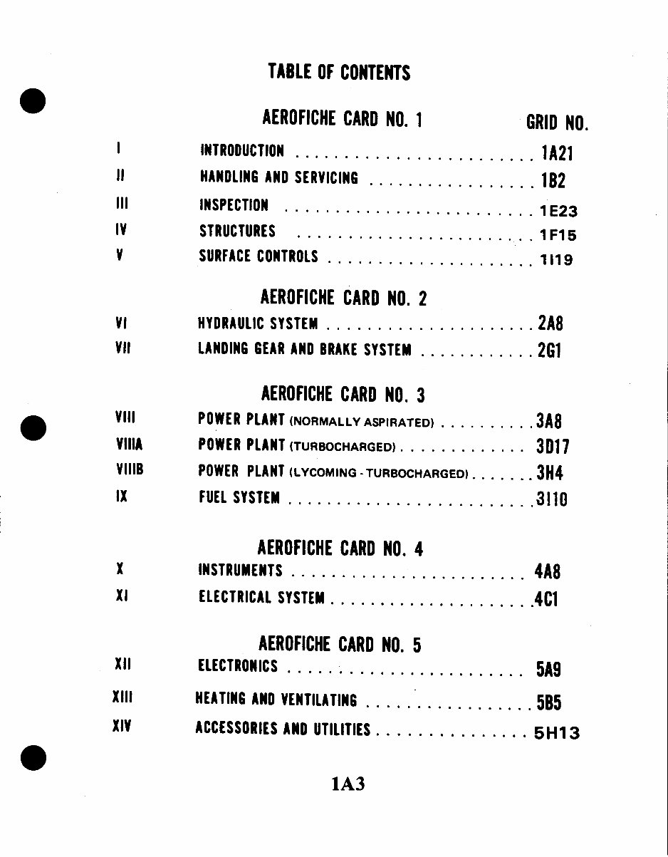
TABLE OF CONTENTS
AEROFICHE
CARD NO. 1
GRID NO.
I
INTRODUCTION
........................
1A21
II
HANDLING AND SERVICING
......... .. ....
1B2
III INSPECTION
............
1 E23
IV STRUCTURES
................
1F15
V SURFACE CONTROLS .................
. 11119
AEROFICHE CARD NO. 2
VI HYDRAULIC SYSTEM ....................
2A8
VII LANDING GEAR AND BRAKE SYSTEM ...........
2G1
AEROFICHE CARD NO. 3
VIII POWER PLANT (NORMALLY ASPIRATED) ..........
3A8
VIIIA POWER PLANT (TURBOCHARGED)
.............
3D17
VIIIB
POWER PLANT (LYCOMING-TURBOCHARGED)
...... 3H4
IX FUEL SYSTEM ........
........... .310
AEROFICHE CARD NO. 4
X INSTRUMENTS
. . ......................
4A8
XI
ELECTRICAL SYSTEM
..... .............
4C1
AEROFICHE CARD NO. 5
XII
ELECTRONICS
.............
. 5A9
XIII HEATING AND VENTILATING ......
... 5B5
XIV
ACCESSORIES
AND UTILITIES ..... .........
5H13
1A3
PIPER AZTEC SERVICE MANUAL
AIRPLANE SERIAL NUMBER LISTING
PA-23-250
PA-23-235
PA-23-250 (six place) "B"
PA-23-250 (six place) "C"
PA-E23-250
PA-23-250 (six place) "D"
PA-23-250 (six place) "E"
PA-23-250 (six place) "F"
Serial Nos. 27-1 to 27-504 incl.
Serial Nos. 27-505 to 27-622 incl.
Serial Nos. 27-2000 to 27-2504 incl.
Serial Nos. 27-2505 to 27-3836 incl.
and 27-3838 to 27-3943 incl.
Start at Serial No. 27-2997
Serial Nos. 27-3837, 27-3944 to
27-4425 incl. and 27-4427 to 27-4573
incl.
Serial Nos. 27-4426, 27-4574 to
27-7554168 incl.
Serial Nos.
27-7654001 to 27-7654203 incl.
27-7754001 to 27-7754162 incl.
27-7854001 to 27-7854139 incl.
27-7954001 to 27-7954121 incl.
27-8054001 to 27-8054059 incl.
27-8154001 to 27-8154030
Reissued:2/18/8
1A4
PIPER AZTEC SERVICE MANUAL
LIST OF ILLUSTRATIONS
Figure
Aerofiche
Grid No.
2-1.
Three-View of PA-23-250 and PA-23-235 ........................
1
2-2. Three-View of PA-23-250 (six place), Serial Nos. 27-2000 to
27-2504 incl .. . ... ..... ......... B7
2-3. Three-View of PA-23-250 (six place), Serial Nos. 27-2505 to
27-4573 incl ...................... . .... . B8
2-4. Three-View of PA-23-250 (six place), Serial Nos. 27-4426
and 27-4574 to 27-7554168 incl ............................
1B9
2-5.
Three-View of PA-23-250, Model "F" Serial Nos. 27-7654001 to
27-7954121 incl . .............. .......... .... 1B10
2-6. Three-View of PA-23-250, Model "F" Serial Nos. 27-8054001
and up . . ..............................................
... IB I
2-7.
Access Plates and Panels, PA-23-250 and PA-23-235 ............ .. IC3
2-8.
Access Plates and Panels, PA-23-250 (six place) ................. IC5
2-9.
Torque Wrench Formula . .....................................
C9
2-10.
Station Reference Lines ...
1............................. 1C13
2-11. Jacking Arrangements ........................................
1
2-12. Weighing ....................................................
IC22
2-13. Longitudinal Leveling .........................................
IC23
2-14. Lateral Leveling ..............................................
1C23
2-15.
Cherrylock Rivet Removal .......................... ........... 1D8
2-16. Hose/Line Markings ..........................................
IDIO
2-17. Flareless Tube Fittings ........................................
IDI I
2-18.
Maximum Distance Between Supports for Fluid Tubing ........... ID12
2-19.
Service Points, PA-23-250 and PA-23-235 ...... .. ............... ID 15
2-20.
Service Points, PA-23-250 (six place), Serial Nos. 27-2000
to 27-2504 incl ...........................................
1D16
2-21.
Service Points, PA-23-250 (six place), Serial Nos. 27-2505 and up... ID17
2-22.
Servicing Landing Gear Oleo Struts .............................
ID19
2-23. Oil Pressure Screen ...... .................................... .. E5
2-24. Oil Suction Screen ... ... ..... ............................... IE5
2-25.
Lubrication Chart, PA-23-250 and PA-23-235 .................... I EII
2-26.
Lubrication Chart, PA-23-250 (six place), Serial Nos.
27-2000 to 27-2504 incl. .. .. ...... ........
IE 15
2-27.
Lubrication Chart, PA-23-250 (six place), Serial Nos.
27-2505 and up...........
............................. IE19
3-1.
Inspection of Outboard Flap Hinge, Serial Nos. 27-3050,
27-3154 to 27-7405330 incl . ..............................
IFI
3-2.
Fuel Selector Valve Control Cables, PA-23-235, PA-23-250, and
PA-23-250 (six place), Serial Nos. 27-2000 thru 27-7954076 ..... IF3
3-3. Fuel Selector Valve Control Cables, PA-23-250 (six place),
Serial Nos. 27-7954077 and up ..............................
1
4-1. Aileron and Flap Installation .................................. IF21
4-2. Fuselage Cradle ..............................................
1G2
4-3. Wing Installation .............................................
IG5
4-4.
Positioning of Front Spar Aligning Tool ... ...................
1
1A5
PIPER AZTEC SERVICE MANUAL
LIST OF ILLUSTRATIONS (cont)
Figure Aerofiche
GridNo.
4-5. Positioning of MainSpar Aligning Tool.................................................................. 1G7
4-6. Emrennage Installation ........................................................................................ 1G13
4-7. Windshield Installation. PA-23-250 and PA-23-235 ............................................. 1G16
4-8. Windshield Installation. PA-23-250 (six place)..................................................... 1G17
4-9. Side WindowInstallation (Typical), PA-23-250, PA-23-235 and
PA-23-250 (six place), Serial Nos.27-2000 to 27-2504 incl.............................. 1G20
4-10. Side Window Installation (Typical), PA-23-250 (six place),
Serial Nos.27-2505and up ........................................ ................... 1G20
4-11. Emergency Exit WindowInstallation, PA-23-250 (six place) ................................. 1 G23
4-12. Cabin Entrance DoorLatchAssembly .................................................................. 1H4
4-13. Typical Access Platesand Panels........................................ ................... 1 H9
4-14. Checking Stabilator Balance ................................................................................. 1H11
4-15. Stabilator Balance Weight- Rework...................................................................... 1H12
4-16. Checking Rudder Balance ........................................ ................... 1H13
4-17. Checking Aileron Balance ........................................ ................... 1H16
4-18. Fuselage Frame Tubing ........................................................................................ 1H18
4-19. SkinMaterials and Thicknesses ........................................................... 1H20
4-20. SkinMaterials andThicknesses, PA-23-250 (six place) ....................................... 1 H22
4-21. Fabricated Tool, Wing Installation ........................................ ................... 1 H24
4-22. Fabricated Tool, Wing Installation ........................................ ...................
4-23. Nose Cone Installation ............................................................ 113
4-24. Removal of Nose Cone/ Radome ........................................ ................... 114
4-25. Nose Cone/Radome ............................................................................................. 115
4-26. Installation of Nose Cone/Radome ....................................................................... 119
4-27. Surface Scratches, Abrasions orGround-in-Dirt .................................................. 1111
4-28. Deep Scratches, Shallow Nicks and Small Holes................................................. 1112
4-29. Mixing or Epoxy Patching Compound .................................................................. 1112
4-30. Welding Repair Method ........................................................... 1113
4-31. Repairing of Cracks ........................................................... ................... 1113
4-32. Various Repairs.....................................................................................................
1114
4-33. Repair of Stress Lines........................................................................................... 1116
4-34. Repair of Impacted Damage ........................................ ................... 1116
5-1. Control Column Installation ........................................ ................... 1J5
5-2. Correct Method of Installing Rod End Bearing...................................................... 1J8
5-3. Aileron Controls ...........................................................................
1J9
5-4. Installation of Aileron Bellcrank Rigging Tool ........................................................ 1J15
5-5. Stabilator andStabilator Trim Controls ................................................................. 1J20
5-6. Stabilator Trim andFlap Interconnect System, PA-23-250,
(sixplace), Serial Nos. 27-7654001 and up ...................................................... 1J24
5-7. Leveling Stabilator, Serial Nos. 27-1 to 27-7554168 incl., and
27-80540001 and up . ........................................................... 1K2
5-8. Leveling Stabilator, Serial Nos. 27-7654001 to 27-7954121 incl ........................... 1K2
5-9. Methods of Blocking Trim Cables ...........................................................
1K6
5-10. Rudder andRudder Trim Controls ........................................................................ 1 K11
5-11. Clamping Rudder Pedals in Neutral .....................................................................1K14
5-12. Installation of Rudder Aligning Tool ........................................ ................... 1K14
5-13. Trim Screw Assembly ........................................ ................... 1 K22
5-14. Flap Controls Installation ........................................ ................... 1K24
5-15. Flap Rigging ....................................................................
1L2
1A6
PIPER AZTEC SERVICE MANUAL
LIST OF ILLUSTRATIONS (cont)
Figure
Aerofiche
Grid No.
5-16. Fabricated Tool, Aileron Rigging ......................
L 15
5-17. Fabricated Tool, Stabilator Leveling, Serial Nos. 27-1 to
27-7554168 incl., and 27-8054001 and up....................
1L
5-18.
Fabricated Tool, Stabilator Leveling, Serial Nos. 27-7645001
to 27-7954121 incl .........................................
1L17
5-19.
Fabricated Tool, Rudder Rigging . .............................. L18
5-20.
Fabricated Tool, Rudder Rigging, PA-23-250 (six place) "F" only... IL 19
6-1.
Hydraulic System Schematic, PA-23-250, PA-23-235 and
PA-23-250 (six place), Serial Nos. 27-2000 to 27-2504 incl...... 2A19
6-2.
Hydraulic System Installation, PA-23-250, PA-23-235 and
PA-23-250 (six place), Serial Nos. 27-2000 to 27-2504 incl...... 2A20
6-3.
Hydraulic System Schematic, PA-23-250 (six place), Serial Nos.
27-2505 to 27-4425 incl.; and 27-4427 to 27-4573 incl ......... 2A21
6-4.
Hydraulic System Installation, PA-23-250 (six place), Serial Nos.
27-2505 to 27-4425 incl.; and 27-4427 to 27-4573 incl ......... 2A22
6-5.
Hydraulic System Schematic, PA-23-250 (six place), Serial Nos.
27-4426 and 27-4574 to 27-7854050 incl ....................
2A23
6-6.
Hydraulic System Installation, PA-23-250 (six place), Serial Nos.
27-4426 and 27-4574 to 27-7954121 incl
2A24
6-7. Hydrualic System Schematic, PA-23-250 (six place), Serial Nos
27-7854051 to 27-7954121 incl. ............................. 2B1
6-8. Hydraulic System Installation PA-23-250 (six place), Serial
Nos. 27-8054001 and up...................................
2B2
6-9. Hydraulic System Schematic
PA-23-250 (six place), Serial Nos.
27-8054001 and up ........................................
2B3
6-10.
Flow Diagram, Both Selector Levers Neutral ..................... 2B4
6-11.
Flow Diagram Landing Gear Selector Lever Up .................. 2B4
6-12.
Flow Diagram, Landing Gear Selector Lever Down............... 2B5
6-13.
Flow Diagram, Flap Selector Lever Down .......................
2B5
6-14.
Flow Diagram, Flap Selector Lever Up ....... ................. 2B6
6-15.
Hydraulic System Checking Diagrams, PA-23-250, PA-23-235,
PA-23-250 (six place), Serial Nos. 27-2000 to
27-2504 incl..............................................
2B13
6-16.
Hydraulic System Checking Diagrams, PA-23-250 (six place),
Serial Nos. 27-2505 and up ..................... ........... 2B15
6-17.
Hydraulic Pump, Exploded View ...............................
2C8
6-18. Identification of Powerpak ....................................
2C 11
6-19.
Location of Powerpak Components ............................. 2C17
6-20.
Hydraulic Powerpak, Exploded View ........ ........ ...... 2C19
6-21.
Checking and Adjusting Powerpak .............................
2D14
6-22.
Checking Powerpak Operation ..................... ............ 2D 14
6-23.
Hydraulic System Check Valve .................................
2D23
6-24.
Anti-Retraction Valve .........................................
2E2
6-25.
Adjustment of Anti-Retraction Valve ...........................
2E4
6-26. Shuttle Valve ...............................................
2E6
6-27.
Nose and Main Landing Gear Actuating Cylinder ................ 2E10
1A7
PIPER AZTEC SERVICE MANUAL
LIST OF ILLUSTRATIONS (cont)
Figure Aerofiche
Grid No.
6-28. Flap Actuating Cylinder ....................................... 2E11
6-29. Nose Gear Door Actuating Cylinder ............................ 2E15
6-30. Main Gear Door Actuating Cylinder ............................ 2E16
6-31. Timer Check Valve ........................................... 2E19
6-32. Priority Valve ................................................ 2E22
6-33. Hydraulic Filter .............................................. 2E24
6-34. Emergency Gear Extender Cable Rigging ........................ 2F3
6-35. Bypass Flow Valve ........................................... 2F4
6-36. Fabricated Work and Test Stand ........................... .... 2F19
6-37. Fabricated Hook ............................................. 2F20
6-38. Fabricated Hook, Double ..................................... 2F20
7-1. Nose Gear Oleo Strut Assembly ............................... . 2G9
7-2. Nose Landing Gear Installation ................................ 2G 14
7-3. Adjustment of Nose Gear Drag Link and Latch Assembly ......... 2G16
7-4. Clamping Rudder Pedals in Neutral ............................ 2G18
7-5. Rudder Pedals Neutral Angle .................................. 2G18
7-6. Aligning the Nose Gear ....................................... 2G20
7-7. Mechanical Nose Gear Door Mechanism, PA-23-250, PA-23-235 and
PA-23-250 (six place), Serial Nos. 27-2000 to 27-2504 incl...... 2G22
7-8. Hydraulic Nose Gear Door Mechanism, PA-23-250 (six place),
Serial Nos. 27-2505 and up ................................ 2G24
7-9. Main Gear Oleo Strut Assembly ................................ 2H3 &
2H4
7-10. Main Landing Gear Installation (Left) .......................... 2H8
7-11. Adjustment of Main Gear Drag Link and Latch Assembly ......... 2H10
7-12. Aligning Main Gear ..................... ..................... 2H12
7-13. Mechanical Main Gear Door Mechanism, PA-23-250, PA-23-235 and
PA-23-250 (six place), Serial Nos. 27-2000 to 27-2504 incl...... 2H14
7-14. Hydraulic Main Gear Door Mechanism, PA-23-250 (six place),
Serial Nos. 27-2505 and up ..................... ........... 2H16
7-15. Deleted ..................................................... 2H18
7-16. Deleted ..................................................... 2H18
7-17. Adjustment of Nose Gear Up Limit Switch ...................... 2H20
7-18. Adjustment of Main Gear Up Limit Switch ...................... 2H21
7-19. Adjustment of Landing Gear Down Limit Switches ............... 2H22
7-20. Landing Gear Warning Switches ............................... 2H24
7-21. Nose Wheel Assembly ......................................... 211
7-22. Main Wheel Assembly ........................................ 212
7-23. Brake Installation ............................................ 214
7-24. Wheel Brake Assembly (Typical) ...................... ......... 218
7-25. Wheel Brake Assembly, Latest Models of PA-23-250 (six place) .... 218
7-26. Removal and Installation of Anchor Bolts ....................... 2110
7-27. Brake Master Cylinder Assembly ............................... 2114
7-28. Parking Brake ValveAssembly ..................... ............ 2116
7-29. Bleeding Brakes .............................................. 2117
7-30. Nose Gear Oleo Service Tolerances ............................. 2119
1A8
PIPER AZTEC SERVICE MANUAL
LIST OF ILLUSTRATIONS (cont)
Figure
Aerofiche
Grid No.
7-31. Main Gear Oleo Service Tolerances ............................. 2122
7-32. Fabricated Tool, Checking Nose Wheel Alignment ............... 2J4
7-33. Tire Balancer . ..................................
2J5
8-1. Cowl Flap Installation ................................. 3A18
8-2. Propeller Installation, PA-23-250, PA-23-235 and PA-23-250
(six place), Serial Nos. 27-2000 to 27-2504 incl ............... 3A20
8-3. Typical Nicks and Removal Method ............................ 3A22
8-4. Propeller Installation, PA-23-250 (six place), Serial Nos.
27-2505 and up . ........................... ........ .. 3A24
8-5. Propeller Governor .....................................
3B10
8-6.
Engine Installation, PA-23-250, PA-23-235 and PA-23-250
(six place), Serial Nos. 27-2000 to 27-2504 incl .............. 3B13
8-7.
Engine Installation, PA-23-250 (six place), Serial Nos.
27-2505 and up...........................................
3B19
8-8. Carburetor ..................................................
3B24
8-9.
Schematic of RSA Fuel Injection System ........................
3C2
8-10. Fuel Injector .................................................
3C6
8-11.
Fuel Air Bleed Nozzle.........................................
3C7
8-12. Magneto Inspection ...........................................
3C8
8-13.
Contact Spring Inspection.....................................
3C9
8-14. Impulse Coupling ............................................
3C9
8-15.
Magneto Timing Marks .......................................
3C12
8-16. Timing Pointer...............................................
3C12
8-17. Timing Kit Installed..........................................
3C14
8-18.
Breaker Compartment with Cast Timing Marks .................. 3C14
8-19.
Engine Timing Marks .........................................
3C16
8-20.
Ignition System Schematic .....................................
3C18
8-21.
Removing Spark Plug Frozen to Bushing ........................
3C19
8-22.
Adjustment of Ball Joint Exhaust System ........................
3C24
8A-1. Cowl Flap Installation ..................................
. 3D24
8A-2. Propeller Installation . .................................
. 3E3
8A-3.
Typical Nicks and Removal Method ............................
3E4
8A-4. Propeller Governor .....................................
. 3EI I
8A-5. Engine Installation ...........................................
3E15
8A-6.
Schematic of RSA Fuel Injection System ........................
3E20
8A-7. Fuel Injector .................................................
3E21
8A-8. Fuel Air Bleed Nozzle .........................................
3E24
8A-9. Contact Points ...............................................
3F2
8A-10. Contact Spring Inspection ................................ .. 3F2
8A-I 1. Rotor Holding Tool Installed ..................................
3F4
8A-12. Timing Kit Installed ....................................
. 3F4
8A-13.
Aligning Timing Marks ....................................
3F6
8A-14.
Forming Leads in Breaker Compartment ........................
3F7
8A-15. Engine Timing Mark ..........................................
3F8
8A-16.
Magneto Timing Mark ........................................
3F8
8A-17.
Removal of Spring From Lead Assembly ........................ 3F9
8A-18. Assembly Tool ..................................
3F10
1A9
PIPER AZTEC SERVICE MANUAL
LIST OF ILLUSTRATIONS (cont)
Figure
Aerofiche
Grid No.
8A-19.
8A-20.
8A-21.
8A-22.
8A-23.
8A-24.
8A-25.
8A-26.
8A-27.
8A-28.
8A-29.
8A-30.
8A-31.
8A-32.
8B-I.
8B-2.
8B-3.
9-1.
9-2.
9-3.
9-4.
9-5.
9-6.
9-7.
9-8.
9-9.
9-10.
9-11.
9-12.
9-13.
9-14.
9-15.
9-16.
9-17.
9-18.
Using Assembling Tool........................................
Measuring Lead Assembly Length ..............................
Cutting Metallic Braid From End of Lead .......................
Unbraiding Metallic Shielding..................................
Forming Shielding Around Ferrule .............................
Ferrule Seating Tool..........................................
Needle ......................................................
Measuring Wire ..............................................
Installing Grommet Over Lead Assemblies.......................
Lead Assembly Installed in Grommet ...........................
Wire Doubled Over for Installation of Eyelet ....................
Ignition System Schematic.....................................
Removing Spark Plug Frozen to Bushing........................
Turbocharger System Diagram .................................
Cowl Flap Installation ........................................
Engine Installation ...........................................
Turbocharger System Diagram ................................
Fuel System Diagram (2 Valves), PA-23-250 and PA-23-250
(six place), Serial Nos. 27-2000 to 27-2222 incl ................
Fuel System Diagram, PA-23-235 and PA-23-250 (six place),
Serial Nos. 27-2223 to 27-2504 incl ..........................
Fuel System Diagram, PA-23-250 (six place), Serial Nos.
27-2322 to 27-2504 incl. ...................................
Fuel System Diagram, PA-23-250 (six place), Serial Nos.
27-2505 to 27-3836; 27-3838 to 27-3943 incl...................
Fuel System Diagram, PA-23-250 (six place), Serial Nos.
27-3937, 27-3944 to 27-7554172 incl. ........................
Fuel System Diagram, PA-23-250 "F", Serial Nos.
27-7654001 and up........................................
Fuel System Diagram, PA-23-250 (six place), Serial Nos.
27-2582, 27-2686, 27-3135 and 27-4520 ......................
Wing Tip Fuel Cell Installation ................................
Fuel Cell Installation, Serial Nos. 27-1 to 27-7654000 incl..........
Fuel Cell Installation, Serial Nos. 27-7654000 and up .............
Fuel Indicating System Wiring Schematic ........................
Check Fuel Quantity Sender ...................................
Check Fuel Gauges Schematic .................................
Fuel Selector Valve...........................................
Fuel Selector Valve Installation, PA-23-250 and PA-23-250
(six place), Serial Nos. 27-2000 to 27-2504 incl ................
Fuel Selector Valve (Scott) ....................................
Fuel Selector Valve Installation, PA-23-235 and PA-23-250
(six place), Serial Nos. 27-2223 to 27-7305126 incl.............
Fuel Selector Valve Port Positions .............................
3F I
3F12
3F12
3F12
3F13
3F13
3F13
3F14
3F14
3F15
3F15
3F16
3F18
3F22
3H9
3H15
3H20
3114
3115
3116
3117
3118
3119
3120
3124
3J2
3J3
3J10
3J11
3JII
3J14
3J15
3J18
3J19
3J21
1A10
You're Reading a Preview
What's Included?
Fast Download Speeds
Online & Offline Access
Access PDF Contents & Bookmarks
Full Search Facility
Print one or all pages of your manual
$52.99
Viewed 13 Times Today


Secure transaction
What's Included?
Fast Download Speeds
Online & Offline Access
Access PDF Contents & Bookmarks
Full Search Facility
Print one or all pages of your manual
$52.99
Piper PA-23 Aztec Service & Repair Manual
Models covered:
- PA-23-235 Apache
- PA-23-250 Aztec
- PA-23-250 (six-place) Aztec
Airplane Serial Number Listing:
- PA-23-250 - Serial Nos. 27-1 to 27-504 incl.
- PA-23-235 - Serial Nos. 27-505 to 27-622 incl.
- PA-23-250 (six place) "B" - Serial Nos. 27-2000 to 27-2504 incl.
- PA-23-250 (six place) "C" - Serial Nos. 27-2505 to 27-3836 incl. and 27-3838 to 27-3943 incl.
- PA-E23-250 - Start at Serial No. 27-2997
- PA-23-250 (six place) "D" - Serial Nos. 27-3837, 27-3944 to 27-4425 incl. and 27-4427 to 27-4573
- PA-23-250 (six place) "E" - Serial Nos. 27-4426, 27-4574 to 27-7554168 incl.
- PA-23-250 (six place) "F" - Serial Nos. 27-7654001 to 27-7654203 incl., 27-7754001 to 27-7754162 incl., 27-7854001 to 27-7854139 incl., 27-7954001 to 27-7954121 incl., 27-8054001 to 27-8054059 incl., 27-8154001 to 27-8154030
Revisions as of November 11, 1972 are as follows:
- Revisions - Date
- ORG600401 - April 1, 1960
- CR810218 - February 18, 1981
- PR830426 - April 26, 1983
- IR860429 - April 29, 1986 (Interim)
- IR860921 - September 21, 1986 (Interim)*
PART NUMBER 753-564


