

Piper PA-18 AIRCRAFT SUPER CUB Illustrated Parts Catalog Manual -
What's Included?
Fast Download Speeds
Online & Offline Access
Access PDF Contents & Bookmarks
Full Search Facility
Print one or all pages of your manual

INTRODUCTION
This Illustrated Parts Catalog is designed to provide simple but positive identification of replacement parts for the Piper
Super Cub (PA-18) Models 95, 105, 125, 135 and 150; and the Piper Agricultural (PA-18A) Models 125, 135 and 150 manu-
factured by the Piper Aircraft Corporation of Lock Haven, Pennsylvania.
NOTE: UhDER NO CIRCUMSTANCES SHALL THIS CATALOG BE USED FOR RIGGING AND INSTALLATlON PURPOSES.
It is suggested that this catalog be thoroughly studied to determine its arrangement prior to its utilization.
1. The catalog is divided into eleven (11) major sections described as follows:
a. Sections I to X inclusive contain all replacement parts for the complete airplane. Each section is suMivided
and each division includes an illustration and a parts listing.
b. Section XI is the Miscellaneous Group. ?his group includes a listing of the Optional Equipment Kits.
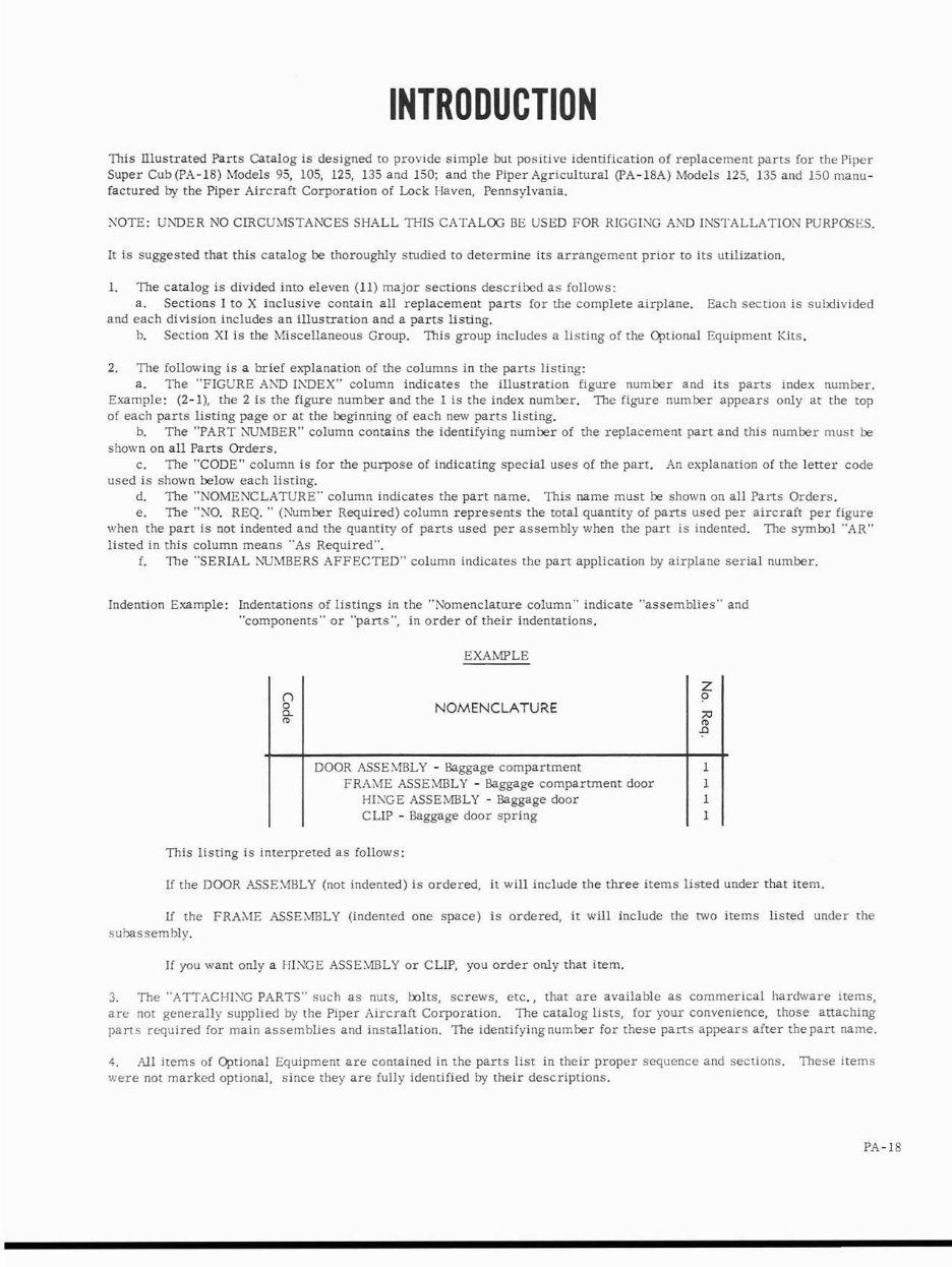
2, The following is a brief explanation of the columns in the parts listing:
a. The "FIGURE AND IADEX" column indicates the illustration figure number and its parts index number.
Example: (2-l), the 2 is the figure number and the 1 is the index number. The figure number appears only at the top
of each parts listing page or at the beginning of each new parts listing.
b. The "PART NUMBER" column contains the identifying number of the replacement part and this number must be
shown on all Parts Orders.
c. The "CODE" column is for the purpose of indicating special uses of the part. An explanation of the letter code
used is shown below each listing.
d. The "NOMENCLATURE" column indicates the part name. This name must be shown on all Parts Orders.
e. The "NO. REQ. " (Number Required) column represents the total quantity of parts used per aircraft per figure
when the part is not indented and the quantity of parts used per assembly when the part is indented. The symbol "AR"
listed in this column means "As Required".
f. The "SERIAL AWMBERS AFFECTED" column indicates the part application by airplane serial number,
Indention Example: Indentations of listings in the "Nomenclature column" indicate "assemblies" and
"components" or 'parts", in order of their indentations.
EXAMPLE
NOMENCLATURE
This listing is interpreted as follows:
DOOR ASSE.MBLY - Baggage compartment
FRAME ASSEMBLY - Baggage compartment door
HISGE ASSE LWLY - Baggage door
CLIP - Baggage door spring
If the DOOR ASSEAMBLY (not indented) is ordered, it will include the three items listed under that item.
1
1
1
1
Lf the FRAME ASSEMBLY (indented one space) is ordered, it will include the two items listed under the
subassembly.
If you want only a HINGE ASSEMBLY or CLIP, you order only that item.
3. The "ATTACHING PARTS" such as nuts, bolts, screws, etc., that are available as commerical hardware items,
are not generally supplied by the Piper Aircraft Corporation. The catalog lists, for your convenience, those attaching
parts required for main assemblies and installation. The identifyingnumber for these parts appears after the part name.
4. All items of Optional Equipment are contained in the parts list in their proper sequence and sections. These items
were not marked optional, since they are fully identified by their descriptions.
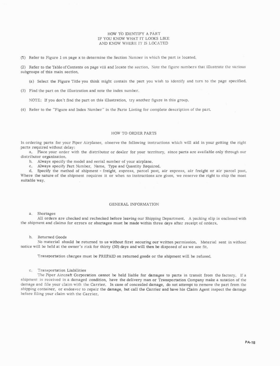
HOW TO IDENTIFY A PART
IF YOU KNOW WHAT IT LOOKS LIKE
AND KNOW WHERE IT IS LOCATED
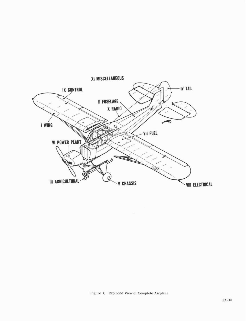
(1) Refer to Figure 1 on page x to determine the Section Numuer in which the part is located.
(2) Refer to the Tableof Contents on page viii and locate the section. Note the figure numbers that illustrate the various
subgroups of this main section.
(a) Select the Figure Title you think might contain the part yo^ wish to identify and turn to the page specified.
(3) Find the part on the illustration and note the index number.
NOTE: If you don't find the part on this illustration, try another figure in this group.
(4) Refer to the "Figure and Index Number" in the Parts Listing for complete description of the part.
HOW TO ORDER PARTS
In ordering parts for your Piper Airplanes, observe the following instructions which will aid in your getting the right
parts required without delay:
a. Place your order with the distributor or dealer for your territory, since parts are available only through our
distributor organization.
b. Always specify the model and serial number of your airplane.
c. Always specify Part Number, Name, Type and Quantity Required.
d. Specify the method of shipment - freight, express, parcel post, air express, air freight or air parcel post.
Where the nature of the shipment requires it or when no instructions are given, we reserve the right to ship the most
suitable way.
GENERAL INFORMATION
a. Shortages
All orders are checked and rechecked before leaving our Shipping Department. A packing slip is enclosed with
the shipment and claims for errors or shortages must be made within three days after receipt of orders.
b. Returned Goods
No material should be returned to us without first securing our written permission. Material sent in without
notice will be held at the owner's risk for thirty (30) days and will then be disposed of a s we see fit.
Transportation charges must be PREPAID on returned goods or the shipment will be refused.
c. Transportation Liabilities
The Piper Aircraft Corporation cannot be held liable for damages to parts in transit from the factory. If a
shipment is received in a damaged condition, have the delivery man or Transportation Company make a notation of the
damage and file your claim with the Carrier. In case of concealed damage, do not attempt to remove the part from the
shipping container, or endeavor to repair the damage, but call the Carrier and have his Claim Agent inspect the damage
hefore filing your claim with the Carrier.
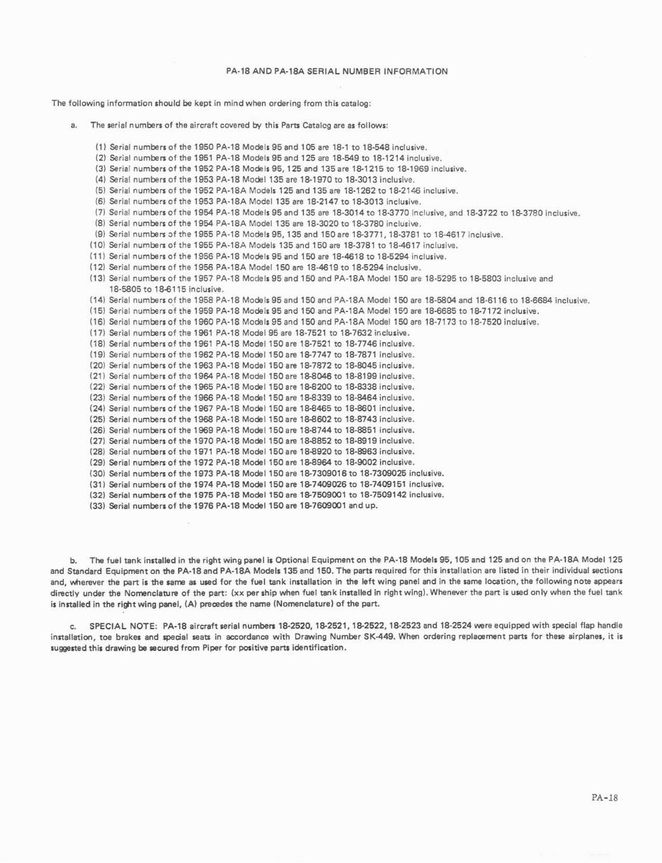
PA-18 AND PA-18A SERIAL NUMBER INFORMATION
The following information should be kept in mind when ordering from this catalog:
a. The serial numbers of the aircraft covered by this Parts Catalcg are as follows:
(1) Serial numbers of the 1950 PA-18 Models 95 and 105 are 18-1 to 18-548 inclusive.
(2) Serial numbers of the 1951 PA-18 Models 95 and 125 are 18-549 to 18-1214 inclusive.
(3) Serial numbers of the 1952 PA-18 Models 95,125 and 135are 18-1215 to 18-1969 inclusive.
(4) Serial numbers of the 1953 PA-18 Model 135 are 18-1970 to 18-3013 inclusive.
(5) Serial numbers of the 1952 PA-18A Models 125 and 135 are 18-1262 to 18-2146 inclusive.
(6) Serial numbers of the 1953 PA-18A Model 135 are 18-2147 to 18-3013 inclusive.
(7) Serial numbers of the 1954 PA-18 Models 95 and 135 are 18-3014 to 18-3770 inclusive, and 18-3722 to 183780 inclusive.
(8) Serial numbers of the 1954 PA-18A Model 135 are 18-3020to IS3780 inclusive.
(9) Serial numbers 3f the 1955 PA-18 Models 95,135 and 150are 18-3771,18-3781 to 18-4617 inclusive.
(1 0) Serial numbers of the 1955 PA-18A Models 135 and 150 an 18-3781 to 18-4617 inclusive.
(11) Serial numbers of the 1956 PA-18 Models 95and 150 are 18-4618 to 18-5294 inclusive.
(12) Serial nurnbers of the 1956 PA-18A Model 150 are 18-4619 to 18-5294 inclusive.
(13) Serial nurnbers of the 1957 PA-18 Models 95 and 150 and PA-18A Model 150 are 18-5295 to 18-5803 inclusive and
18-5805 to 18-6115 inclusive.
(14) Serial nurnbers of the 1958 PA-18 Models 95 and 150 and PA-18A Model 150 are 18-5804and 18-61 16 to 18-6684 inclusive.
(15) Serial numbers of the 1959 PA-18 Models 95 and 150 and PA-18A Model 159 are 18-6685 to 18-7172 inclusive.
(16) Serial numbers of the 1960 PA-18 Models 95 and 150 and PA-18A Model 150 are 18-71 73 to 18-7520 inclusive.
(1 7) Serial numbers of ;he 1961 PA-18 Model 95 are 18-7521 to 18-7632 inclusive.
(18) Serial numbers of the 1961 PA-18 Model 150 are 18-7521 to 18-7746 inclusive.
(19) Serial numbers of the 1962 PA-18 Model 150are 18-7747 to 18-7871 inclusive.
(20) Serial numbers of the 1963 PA-18 Model 150are 18-7872 to 18-8045 inclusive.
(21) Serial numbers of the 1964 PA-18 Model 150 are 18-8046 to 18-8199 inclusive.
(22) Serial numbers of the 1965 PA-18 Model 150are 18-8200 to 18-8338 inclusive.
(23) Serial numbers of the 1966 PA-18 Model 150 are 18-8339 to 18-8464 inclusive.
(24) Serial numbers of the 1967 PA-18 Model 150 are 18-8465 to 18-8601 inclusive.
(25) Serial numbers of the 1968 PA-18 Model 150are 18-8602 to 18-8743 inclusive.
(26) Serial numbers of the 1969 PA-18 Model 150are 18-8744 to 18-8851 inclusive.
(27) Serial numbers of the 1970 PA-18 Model 150 are 188852 to 18-8919 inclusive.
(28) Serial numbers of the 1971 PA-18 Model 150are 188920 to 18-8963 inclusive.
(29) Serial numbers of the 1972 PA-18 Model 150 are 18-8964 to 18-9002 inclusive.
(30) Serial numbers of the 1973 PA-18 Model 150 are 18-730901 6 to 18-7309025 inclusive.
(31) Serial numbers of the 1974 PA-18 Model 150are 18-7409026 to 18-7409151 inclusive.
(32) Serial numbers of the 1975 PA-18 Model 150are 187509001 to 18-7509142 inclusive.
(33) Serial numbers of the 1976 PA-18 Model 150 are 18-7609001and up.
b. The fuel tank installed in the right wing panel is Optional Equipment on the PA-18 Models 95,105 and 125 and on the PA-18A Model 125
and Standard Equipment on the PA-18 and PA-18A Models 135 and 150. The parts required for this installation are listed in their individual sections
and, wherever the part is the same as used for the fuel tank installation in the left wing panel and in the same location, the following note appears
directly under the Nomenclature of the part: (xx per ship when fuel tank installed in right wing). Whenever the part is used only when the fuel tank
is installed in the right wing panel, (A) precedes the name (Nomenclature) of the part.
c. SPECIAL NOTE: PA-18 aircraft serial numbers 18-2520, 18-2521, 18-2522, 18-2523 and 18-2524 were equipped with special flap handle
installation, toe brakes and speaal seats in accordance with Drawing Number SK-449. When ordering repla~ment parts for these airplanes, it is
suggestedthis drawing be secured from Piper for positive parts identification.
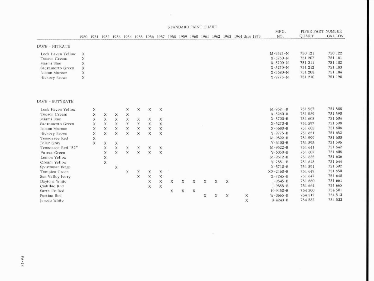
DOPE - NITRATE
Lock Haven Yellow X
Tucson Cream X
Miami Blue X
Sacramento Green X
I3oston Maroon X
Hickory I3rown X
DOPE - BLJTYRATE
Lock Haven Ycllow
Tucson Cream
M~an~l Blue
Sacramento Green
I3oston Maroon
l l~ckory I3rown
Tennessee Ked
Polar Gray
Tennessee Red "52"
Forest Green
Lemon Yellow
Crea~ri Yellow
Sportsman kip
Tampico (;rc,en
Sun Valley Ivory
Daytona Whitc
Cad~llac Itod
Santa Fc Rcd
Pontlac Red
Juncau Whltc
STANDARD PAINT CHART
1957 1958 1959 1960 1961 1962
MFG. PIPER PART NUMBER
1963 1964 chru 1973 NO. QUART GALLON
X X X X X
X X X X
X X X X X X X
X X X X X X X
X X X X X X X
X X X X X X X
X
X X X
X X X X X X
X X X X X X
X
X
X
X X X X
X X X
X X X X X X X X
X X
X X X
X X X X
X
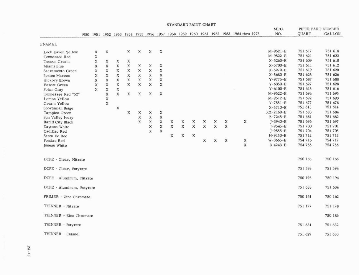
STANDARD PAINT CHART
MFG. PIPER PART NUMBER
1950 1951 1952 1953 1954 1955 1956 1957 1958 1959 1960 1961 1962 1963 1964thru 1973 NO. QUART GALLON
ENAMEL
Lock Haven Yellow X X X X X X M-9521-E 751 617 751 618
Tennessee Red X 751 621 751 622
M-9522-E
Tucson Cream X X X X X-5260-E 751 609 751 610
Miami Blue X X X X X X X X-5700-E 751 611 751 612
Sacramento Green X X X X X X X
X-5270-E 751 619 751 620
Boston Maroon X X X X X X X 751 625 751 626
X-5680-E
Hickory Brown X X X X X X X Y-9775 -E 751 687 751 688
Forest Green X X X X X X X Y -6350-E 751 627 751 628
Polar Gray X X X Y-6100-E 751 615 751 616
Tennessee Red "52" X X X X X X M -9522 -E 751 694 751 695
Lemon Yellow X M-9512 -E 751 692 751 693
Cream Yellow X Y-7551-E 751 677 751 678
Sportsman Beige X X-5710-E 751 613 751 614
Tampico Green XZ-2160-E 751 683 751 684
Sun Valley Ivory Z -7245-E 751 681 751 682
Rapid City Black J-3940-E 75 1 696 751 697
Daytona White J-9545 -E 751 700 751 701
Cadillac Red J-9555-E 751 704 751 705
Santa Fe Red H-9150-E 751 712 751 713
Pontiac Red W-3665-E 754 716 754 717
Juneau White B-4243-E 754 755 754 756
X X X X
X X X
X X X X X X X X X X
X X X X X X X X
X X
X X X
X X X X
X
DOPE - Clear, Nitrate
DOPE - Clear, Butyrate
DOPE - Aluminum. Nitrate
DOPE - Aluminum, Butyrate
PRIMER - Zinc Chromate
THINNER - Nitrate
THINNER - Zinc Chromate
THINNER - Butyrate
THINNER - Enamel
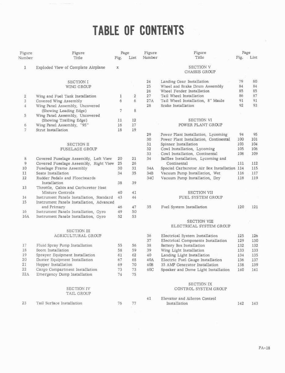
TABLE OF CONTENTS
Figure
Number
Figure
Title
Page Figure
Fig. List Number
Figure
Title
Page
Fig. . List
Exploded View of Complete Airplane x SECTION V
CHASSIS GROUP
SECTION I
WING GROW
Landing Gear Installation
Wheel and Brake Drum Assembly
Wheel Fender Installation
Tail Wheel Installation
Tail Wheel Installation, 8" Maule
Brake Installation
Wing and Fuel Tank Installation
Covered Wing Assembly
Wing Panel Assembly, Uncovered
(Showing Leading Edge)
Wing Panel Assembly, Uncovered
(Showing Trailing Edge)
Wing Panel Assembly, "95"
Strut Installation
SECTION VI
POWER PLANT GROUP
Power Plant Installation, Lycoming
Power Plant Installation, Continental
Spinner Installation
Cowl Installation, Lycoming
Cowl Installation, Continental
Baffles Installation, Lycoming and
Continental
Special Carburetor Air Box Installation
Vacuum Pump Installation, Wet
Vacuum Pump Installation, Dry
SECTION I1
FUSELAGE GROUP
Covered Fuselage Assembly, Left View
Covered Fuselage Assembly, Right View
Fuselage Frame Assembly
Seats Installation
Rudder Pedals and Floorboards
Installation
Throttle, Cabin and Carburetor Heat
Mixture Controls
Instrument Panels Installation, Standard
Instrument Panels Installation, Advanced
and Primary
Instrument Panels Installation, Gyro
Instrument Panels Installation, Gyro
SECTION VII
FUEL SYSTEM GROUP
Fuel System Installation
SECTION VIII
ELECTRICAL SYSTEM GROUP
SECTION I11
AGRICULTURAL GROUP Electrical System Installation
Electrical Components Installation
Battery Box Installation
Wing Light Installation
Landing Light Installation
Electric Fuel Gauge Installation
35 AMP Generator Installation
Speaker and Dome Light Installation
Fluid Spray Pump Installation
Boom Installation
Sprayer Equipment Installation
Duster Equipment Installation
Hopper Installation
Cargo Compartment Installation
Emergency Dump Installation
SECTION IX
CONTROL SYSTEM GROUP SECTION IV
TAIL GROUP
41
Tail Surface Installation 76 77
Elevator and Aileron Control
Installation
Figure
Number
Figure
Title
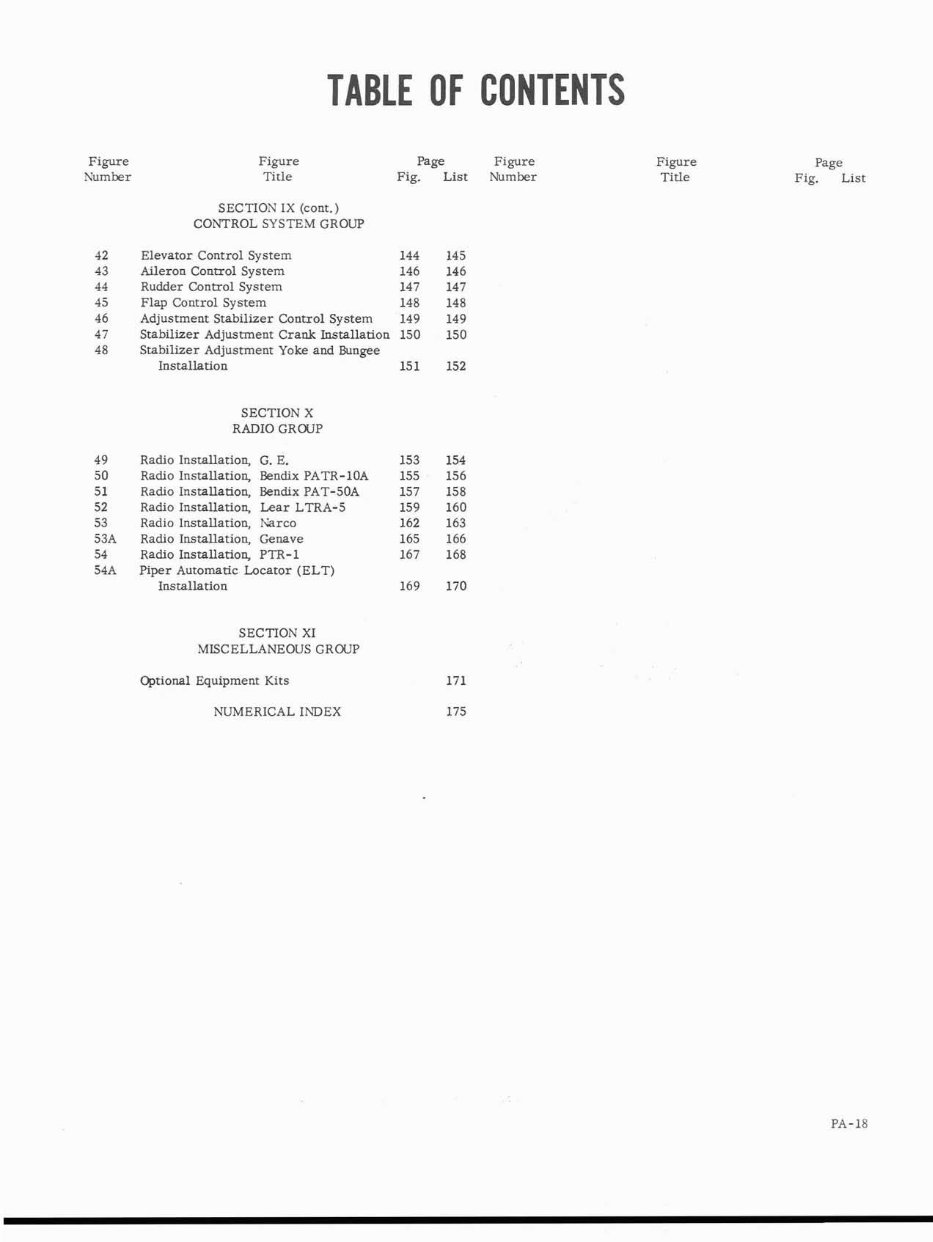
TABLE OF CONTENTS
SECTION IX (cont.)
CONTROL SYSTEM GROUP
page Figure
Fig. List Number
Elevator Control System 144 145
Aileron Control System 146 146
Rudder Control System 147 147
Flap Control System 148 148
Adjustment Stabilizer Control System 149 149
Stabilizer Adjustment Crank Installation 150 150
Stabilizer Adjustment Yoke and Wlngee
Installation 151 152
SECTION X
RADIO GROUP
Radio Installation, G. E.
Radio Installation, Bendix PATR-1OA
Radio Installation, Bendix PAT-50A
Radio Installation, Lear LTRA-5
Radio Installation, Wrco
Radio Installation, Genave
Radio Installation, PTR-1
Piper Automatic Locator (ELT)
Installation
SECTION XI
MISCELLANEOUS GROUP
Optional Equipment Kits
Figure
Title
Page
Fig. List
NUMERICAL INDEX
You're Reading a Preview
What's Included?
Fast Download Speeds
Online & Offline Access
Access PDF Contents & Bookmarks
Full Search Facility
Print one or all pages of your manual
$35.99
Viewed 96 Times Today


Secure transaction
What's Included?
Fast Download Speeds
Online & Offline Access
Access PDF Contents & Bookmarks
Full Search Facility
Print one or all pages of your manual
$35.99
This Illustrated Parts Catalog is designed to provide simple but positive identification of replacement parts for the Piper Super Cub (PA-18) Models 95, 105, 125, 135, and 150; and the Piper Agricultural (PA-18A) Models 125, 135, and 150 manufactured by the Piper Aircraft Corporation of Lock Haven, Pennsylvania.
This manual is clear and written in a way so that just about anybody can follow it. It is bookmarked, allowing you to find what you need to know quickly. Just click on the bookmark, and that page comes up. Additionally, it is searchable, enabling you to type in what you are looking for, and the page will come up.
Print what you need when you need it and save a tree by buying digitally!


