

Piper Altimatic 3C AutoPilot service manual Auto-pilot
What's Included?
Fast Download Speeds
Online & Offline Access
Access PDF Contents & Bookmarks
Full Search Facility
Print one or all pages of your manual
PIPER
ALTIMATIC IIIC
Se,vice Manual
PIPER AIRCRAFT CORPORATION
761 602
Piper Aircraft Corporation; Vero Beach, Florida
U.S. A.
Published by
PUBLICATIONS DEPARTMENT
Piper Aircraft Corporation
761 602
Issued: November 1974
PIPER ALTIMATIC IIIC SERVICE MANUAL
REVISIONS ISSUED
Current, Permanent and Temporary Revisions to this AltiMatic mc
Service Manual issued November 1974 are as follows:
761 602 (PR750613)
761 602 (PR770415)
761 602 (PR78031O)
761 602 (PR78081O)
761 602 (PR791130)
761602 (PRRIIOI6)
REVISED: 10/16/81
Permanent Revision
Permanent Revision
Permanl;!nt Revision
Permanent Revision
Permanent Revision
Permanent Revision
Dated June 13, 1975
Dated April 15, 1977
Dated March 10, 1978
Dated August 10, 1978
Dated November 30, 1979
Dated October 16, 1981
III
PIPER ALTIMATIC IIIC SERVICE MANUAL
FOREWORD
This Service Manual is provided as a guide for Removal and Installation, Troubleshooting Procedures,
and Set-Up Procedures for the Piper AltiMatic IIIC.
The information presented in this manual has been divided into three parts; Part I contains six (6)
sections, Part II contains six (6) sections and Part III contains three (3) sections.
The information compiled in this manual will be kept current by revisions distributed periodically to
the manual owner through their local Piper Dealer or Distributor.
REVISION
There will be two (2) types of revisions used to keep this manual current. The material compiled in
these revisions will consist of information necessary to maintain the present AltiMatic lIle. Therefore, it is
imperative that this material be inserted in the Service Manual at the time it is received.
I. Temporary Revision
This type revision will be distributed at any time it is necessary to forward Technical Servicing
Information to the field. The temporary revision will usually consist of one or two pages which may be
inserted in the front of the manual. These revisions will include deletions and additions of material
pertinent to different paragraphs of the service manual. Therefore, when the temporary revision is received,
review the manual and mark the affected paragraph with the code date of the latest revision for a ready
reference.
II. Permanent Revision
This type revision will be distributed periodically and will supersede all previous temporary revisions.
These revisions will be of complete page replacement and shall be inserted in the service manual in
accordance with the following instructions:
1. Replace the obsolete pages with revised pages of the same page number.
2. Insert pages with page numbers followed by a small letter in direct sequence with the same
common page number.
3. Insert pages with page numbers followed by a capital letter in direct sequence with the same
COllllllon page number but after any pages with the same common page number followed by a small letter.
ISSUED: 11/25/74 v
PIPERALTIMATIC IIIC SERVICE MANUAL
III. Identification of Revised Material
Revised text and illustrations shall be indicated by a black vertical line along the left-hand margin of
the page opposite the change. A line opposite the page number or section title and printing date will
indicate that the text or illustration was unchanged, but the material was relocated to a different page.
Newly added material shall be identified by an arrow pointing toward either the text, text heading or
illustration. When material is removed, an arrow will point away from the area from which the material was
removed.
Symbols will indicate only current revisions with changes and additions to or deletions of existing text
and illustrations. Changes in capitalization, spelling, punctuation or the physical location of the material on
the page will not be identified by symbols.
vi ISSUED: 11/25/74
PIPER ALTIMATIC IIIC SERVICE MANUAL
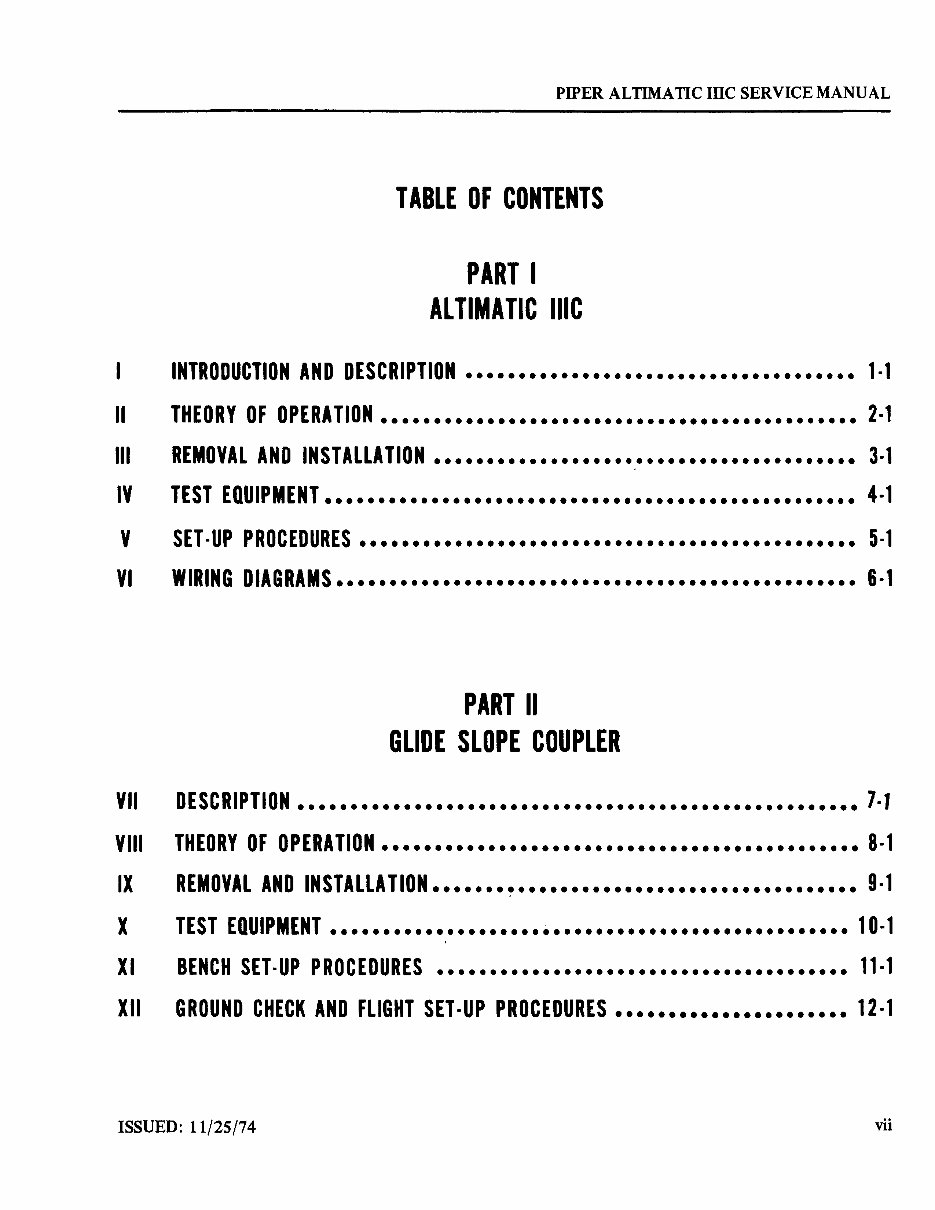
TABLE OF CONTENTS
PART I
ALTIMATIC IIIC
INTRODUCTION AND DESCRIPTION ..................................... 1·1
II THEORY OF OPERATION ••••••••••••••••••••••••••••••••••••••••••••• 2·1
III REMOVAL AND INSTALLATION ........................................ 3·1
IV TEST EQUiPMENT •••••••••••••••••••••••••••••••••••••••••••••••••• 4·1
V SET· UP PROCEDURES ••••••••••••••••••••••••••••••••••••••••••••••• 5·1
VI WIRING DIAGRAMS ••••••••••••••••••••••••••••••••••••••••••••••••• 6·1
PART II
GLIDE SLOPE COUPLER
VII DESCRiPTION ••••••••••••••••••••••••••••••••••••••••••••••••••••• 7· J
VIII THEORY OF OPERATION ............................................. 8·1
IX REMOVAL AND INSTALLATION •••••••••••••••••••••••••••••••••••••••• 9·1
X TEST EQUiPMENT ••••••••••••••••••••••••••••••••••••••••••••••••• 10·1
XI BENCH SET·UP PROCEDURES ••••••••••••••••••••••••••••••••••••••• 11·1
XII GROUND CHECK AND FLIGHT SET ·UP PROCEDURES •••••••••••••••••••••• 12·1
ISSUED: 11/25/74
vii
PIPER ALTIMATIC IIIC SERVICE MANUAL
XIII
XIV
~ XV
.. XVI
viii
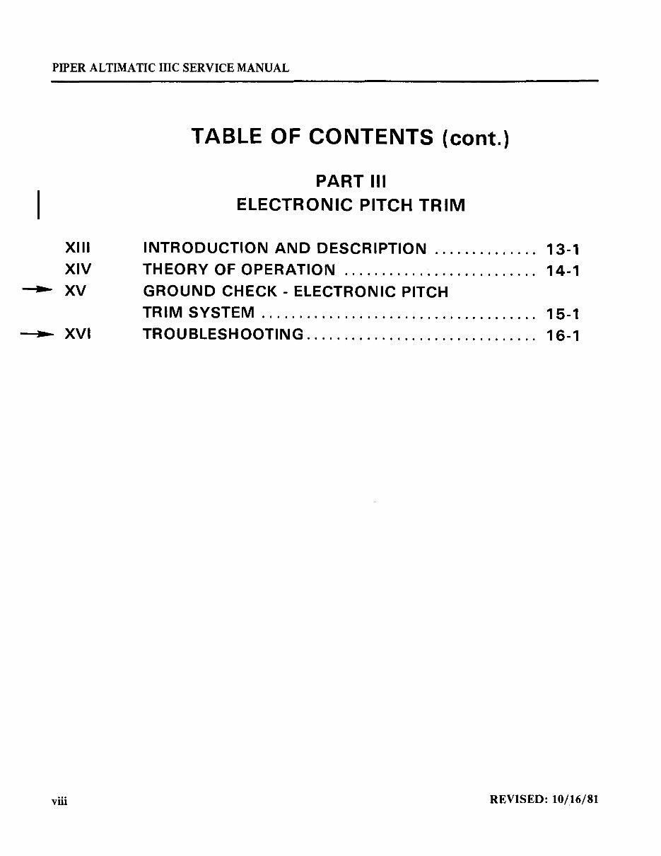
TABLE OF CONTENTS (cont.)
PART III
ELECTRONIC PITCH TRIM
INTRODUCTION AND DESCRIPTION" " .......... 13-1
THEORY OF OPERATION ........... '" ........ " ... 14-1
GROUND CHECK - ELECTRONIC PITCH
TRIM SYSTEM ..................................... 15-1
TROUBLESHOOTING .......................... " ... 16-1
REVISED: 10/16/81
Figure
2-1.
3-1.
3-2.
3-3.
3-4.
3-5.
3-6.
3-7.
3-7a.
3-8.
3-9.
3-10.
3-11.
3-12.
3-13.
3-14.
3-\5.
3-16.
3-17.
3-18.
3-19.
3-20.
3-21.
3-22.
3-23.
3-24.
3-25.
3-26.
3-27.
3-28.
3-29.
3-30.
3-31.
3-32.
PIPER ALTIMATIC IIIC SERVICE MANUAL
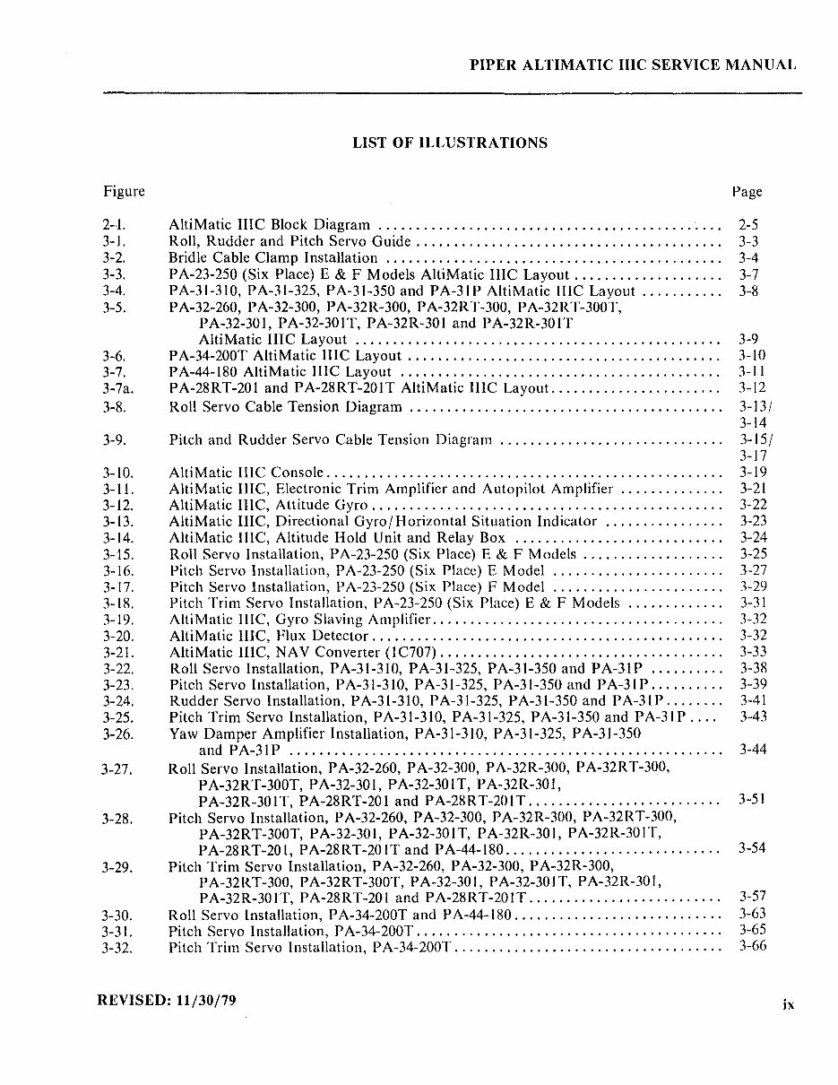
LIST OF ILLUSTRATIONS
Page
AltiMatic HIC Block Diagram .............................................. 2-5
Roll, Rudder and Pitch Servo Guide ....................................... " 3-3
Bridle Cable Clamp Installation ............................................. 3-4
PA-23-250 (Six Place) E & F Models AltiMatic IIlC Layout .................... 3-7
PA-31-31O, PA-31-325, PA-31-350 and PA-3IP AltiMatic mc Layout ........... 3-8
PA-32-260, PA-32-300, PA-32R-300, PA-32RT-300, PA-32RT-300T,
PA-32-301, PA-32-301T, PA-32R-301 and PA-32R-301T
AltiMatic IIIC Layout ................................................ .
PA-34-200T AltiMatic lllC Layout ......................................... .
PA-44-180 AltiMatic IIIC Layout .......................................... .
PA-28RT-201 and PA-28RT-201T AltiMatic IllC Layout. ..................... .
Roll Servo Cable Tension Diagram ......................................... .
Pitch and Rudder Servo Cable Tension Diagram ............................. .
AltiMatic IIlC Console .................................................... .
AltiMatic IIlC, Electronic Trim Amplifier and Autopilot Amplifier ............. .
AltiMatic IIlC, Attitude Gyro .............................................. .
AltiMatic IIlC, Directional Gyro / Horizontal Situation Indicator ............... .
AltiMatic IIlC, Altitude Hold Unit and Relay Box ........................... .
Roll Servo Installation, PA-23-250 (Six Place) E & F Models. " .............. "
Pitch Servo Installation, PA-23-250 (Six Place) E Model .................... '"
Pitch Servo Installation, PA-23-250 (Six Place) F Model ...................... .
Pitch Trim Servo Installation, PA-23-250 (Six Place) E & F Models ............ .
AltiMatic Ille, Gyro Slaving Amplifier. ..................................... .
AltiMatic tIlC, Flux Detector .............................................. .
AltiMatic lIIC, NAY Converter (IC707) ..................................... .
Roll Servo Installation, P A-3\-31 0, P A-31-325, P A-3\-350 and P A-3\ P ......... .
Pitch Servo Installation, PA-31-31O, PA-31-325, PA-31-350 and PA-3IP ......... .
Rudder Servo Installation, P A-31-31O, P A-31-325, P A-3\-350 and P A-31 P ....... .
Pitch Trim Servo Installation, P A-31-31O, P A-31-325, P A-31-350 and P A-31 P ... .
Yaw Damper Amplifier Installation, PA-31-31O, PA-31-325, PA-31-350
and PA-3IP ......................................................... .
Roll Servo Installation, PA-32-260, PA-32-300, PA-32R-300, PA-32RT-300,
PA-32RT-300T, PA-32-301, PA-32-301T, PA-32R-301,
PA-32R-301T, PA-28RT-201 and PA-28RT-20IT ........................ "
Pitch Servo Installation, PA-32-260, PA-32-300, PA-32R-300, PA-32RT-300,
PA-32RT-300T, PA-32-301, PA-32-301T, PA-32R-301, PA-32R-30IT,
PA-28RT-201, PA-28RT-201T and PA-44-180 ............................ .
Pitch Trim Servo Installation, PA-32-260, P A-32-300, PA-32R-300,
PA-32RT-300, PA-32RT-300T, PA-32-301, PA-32-30IT, PA-32R-301,
PA-32R-30IT, PA-28RT-201 and PA-28RT-20IT ......................... .
Roll Servo Installation, PA-34-200T and PA-44-180 ........................... .
Pitch Servo Installation, PA-34-200T ........................................ .
Pitch Trim Servo Installation, PA-34-200T ................................... .
3-9
3-10
3-11
3-12
3-13/
3-14
3-15/
3-17
3-\9
3-2\
3-22
3-23
3-24
3-25
3-27
3-29
3-31
3-32
3-32
3-33
3-38
3-39
3-41
3-43
3-44
3-5\
3-54
3-57
3-63
3-65
3-66
REVISED: 11/30/79
ix
PIPER ALTIMA TIC IIIC SERVICE MANUAL
Figure
3-33 .•
3-34.
3-35.
3-36.
3-37.
4-\.
4-2.
4-3.
4-4.
4-5.
5-1.
5-2.
5-3.
5-4.
5-5.
5-6.
5-7.
5-8.
5-9.
5-10.
5-11.
5-12.
---- 5-13.
~5-14.
6-\.
6-2.
6-3.
6-4.
6-5.
6-6.
6-7.
6-8.
6-8a.
6-8b.
6-9.
6-10.
6-11.
6-lla.
6-12.
6-13.
6-14.
6-15.
x
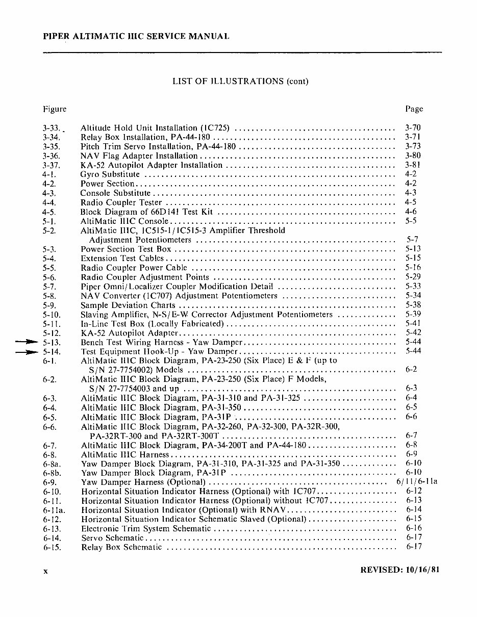
LIST OF ILLUSTRATIONS (cont)
Page
Altitude Hold Unit Installation (I C725) ...................................... 3-70
Relay Box Installation, PA-44-180 . . . . . . . . . . . . . . . . . . . . . . . . . . . . . . . . . . . . . . . . . .. 3-71
Pitch Trim Servo Installation, PA-44-180 .............................. ....... 3-73
NA V Flag Adapter Installation. . . . . . . . . . . . . . . . . . . . . . . . . . . . . . . . . . . . . . . . . . . . . . 3-80
KA-52 Autopilot Adapter Installation. . . . . . . . . . . . . . . . . . . . . . . . . . . . . . . . . . . . . . . . 3-81
Gyro Substitute. . . . . . . . . . . . . . . . . . . . . . . . . . . . . . . . . . . . . . . . . . . . . . . . . . . . . . . . . . . 4-2
Power Section. . . . . . . . . . . . . . . . . . . . . . . . . . . . . . . . . . . . . . . . . . . . . . . . . . . . . . . . . . . . . 4-2
Console Substitute. . . . . . . . . . . . . . . . . . . . . . . . . . . . . . . . . . . . . . . . . . . . . . . . . . . . . . . . . 4-3
Radio Coupler Tester. . . . . . . . . . . . . . . . . . . . . . . . . . . . . . . . . . . . . . . . . . . . . . . . . . . . .. 4-5
Block Diagram of 66D 141 Test Kit.. . . . . . . . . . . . . . . . . . . . . . . . . . . . . . . . . . . . . . . . . 4-6
AltiMatic lIIC Console. . . . . . . . . . . . . . . . . . . . . . . . . . . . . . . . . . . . . . . . . . . . . . . . . . . .. 5-5
AltiMatic mc, lC515-1 I lC515-3 Amplifier Threshold
Adjustment Potentiometers ......................... '.' . . . . . . . . . . . . . . . . . . . . 5-7
Power Section Test Box .. . . . . . . . . . . . . . . . . . . . . . . . . . . . . . . . . . . . . . . . . . . . . . . . . . . 5-13
Extension 'rest Cables. . . . . . . . . . . . . . . . . . . . . . . . . . . . . . . . . . . . . . . . . . . . . . . . . . . . . . 5-15
Radio Coupler Power Cable. . . . .. . . . . . . . . . . . . . . . . . . . . . . . . . . . . . . . . . . . . . . . . .. 5-16
Radio Coupler Adjustment Points.. . . . . . . . . . . . . . . . . . . . . . . . . . . . . . . . . . . . . . . . . . 5-29
Piper Omni/Localizer Coupler Modification Detail ............................ 5-33
NA V Converter (I C707) Adjustment Potentiometers ........................... 5-34
Sample Deviation Charts. . . . . . . . . . . . . . . . . . . . . . . . . . . . . . . . . . . . . . . . . . . . . . . . . .. 5-38
Slavi ng Amplifier, N~S I E- W Corrector Adjustment Potentiometers .............. 5-39
In-Line Test Box (Locally Fabricated) . . . . . . . . . . . . . . . . . . . . . . . . . . . . . . . . . . . . . . .. 5-41
KA-52 Autopilot Adapter. . . . . . . . . . . . . . . . . . . . . . . . . . . . . . . . . . . . . . . . . . . . . . . . . .. 5-42
Bench Test Wiring Harness - Yaw Damper. . . . . . . . . . . . . . . . . . . . . . . . . . . . . . . . . . .. 5-44
Test Equipment Hook-Up - Yaw Damper. . . . . . . . . . . . . . . . . . . . . . . . . . . . . . . . . . . .. 5-44
AltiMatic lllC Block Diagram, PA-23-250 (Six Place) E & F (up to
SIN 27-7754002) Models ......... .... ............. ....... ...... .. ........ 6-2
AltiMatic lIIC Block Diagram, PA-23-250 (Six Place) F Models,
SIN 27-7754003 and up .................................................. 6-3
AltiMatic mc Block Diagram, PA-31-310 and PA-31-325 . . .. . . . . . . . . . . . . . . . . . . 6-4
AltiMatic mc Block Diagram, PA-31-350 . . . . . . . . . . . . . . . . . . . . . . . . . . . . . . . . . . .. 6-5
AltiMatic mc Block Diagram, PA-31 P ......... . . . . . . . . . . . . . . . . . . . . . . . . . . . .. 6-6
AltiMatic mc Block Diagram, PA-32-260, PA-32-300, PA-32R-300,
PA-32RT-300 and PA-32RT-300T ... ......... ........ ........ .... ......... 6-7
AltiMatic lllC Block Diagram, PA-34-200T and PA-44-180 ............. ........ 6-8
AltiMatic HIC Harness. . . . . . . . . . . . . . . . . . . . . . . . . . . . . . . . . . . . . . . . . . . . . . . . . . . .. 6-9
Yaw Damper Block Diagram, PA-31-31O, PA-31-325 and PA-31-350 ............. 6-10
Yaw Damper Block Diagram, PA-31 P ....................................... 6-10
Yaw Damper Harness (Optional) . . . . . . . . . . . . . . . . . . . . . . . . . . . . . . . . . . . . . . . . .. 61 II 16-lla
Horizontal Situation Indicator Harness (Optional) with 1 C707 . . . . . . . . . . . . . . . . . .. 6-12
Horizontal Situation Indicator Harness (Optional) without IC707. . . . . . . . . . . . . . . . 6-13
Horizontal Situation Indicator (Optional) with RNA V . . . . . . . . . . . . . . . . . . . . . . . . . . 6-14
Horizontal Situation Indicator Schematic Slaved (Optional) ............. .... .... 6-15
Electronic Trim System Schematic. . . . . . . . . . . . . . . . . . . . . . . . . . . . . . . . . . . . . . . . . .. 6-16
Servo Schematic. . . . . . . . . . . . . . . . . . . . . . . . . . . . ... . . . . . . . . . . . . . . . . . . . . . . . . . . . . . 6-17
Relay Box Schematic ...................................................... 6-17
REVISED: 10/16/81
Figure
6-16.
6-17.
6-18.
6-19.
6-20.
6-21.
6-22.
6-23.
6-24.
6-25.
6-26.
6-27.
6-28.
6-29.
6-30.
6-31.
6-32.
7-1.
8-1.
8-2.
8-3.
9-1.
9-2.
9-3.
9-4.
9-5.
10-1.
11-1.
11-2.
J 1-3.
~ 15-1.
PIPER ALTIMATIC IIIC SERVICE MANUAL
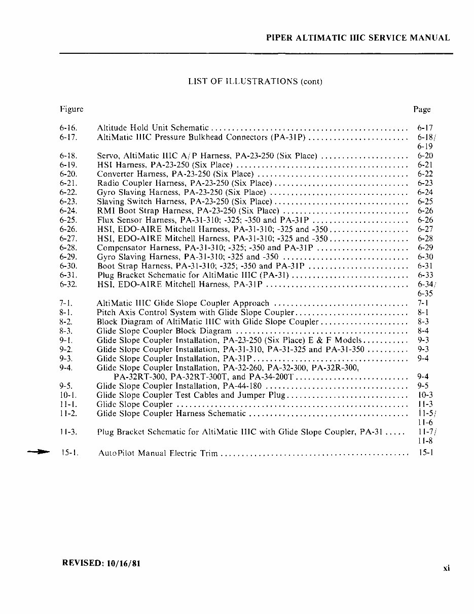
LIST OF ILLUSTRATIONS (cont)
Altitude Hold Unit Schematic .............................................. .
AltiMatic IIIC Pressure Bulkhead Connectors (PA-31 P) ....................... .
Servo, AltiMatic IIIC AI P Harness, PA-23-250 (Six Place) .................... .
HSI Harness, PA-23-250 (Six Place) ........................................ .
Converter Harness, PA-23-250 (Six Place) ................................... .
Radio Coupler Harness, PA-23-250 (Six Place) ............................... .
Gyro Slaving Harness, PA-23-250 (Six Place) ................................ .
Slaving Switch Harness, PA-23-250 (Six Place) ............................... .
RMI Boot Strap Harness, PA-23-250 (Six Place) " ........... , ............... .
Flux Sensor Harness, PA-3 1-3 10; -325; -350 and PA-31 P ...................... .
HSI, EDO-AIRE Mitchell Harness, PA-31-310; -325 and -350 .................. .
HSI, EDO-AIRE Mitchell Harness, PA-31-310; -325 and -350 .................. .
Compensator Harness, P A-31-31 0; -325; -350 and P A-31 P ..................... .
Gyro Slaving Harness, PA-31-310; -325 and -350 ............................. .
Boot Strap Harness, PA-31-310; -325; -350 and PA-31 P ....................... .
Plug Bracket Schematic for AltiMatic IlIC (PA-31) ........................... .
HSI, EDO-AIRE Mitchell Harness, PA-31 P ................................. .
AltiMatic IIIC Glide Slope Coupler Approach ............................... .
Pitch Axis Control System with Glide Slope Coupler .......................... .
Block Diagram of AltiMatic IIlC with Glide Slope Coupler .................... .
Glide Slope Coupler Block Diagram ........................................ .
Glide Slope Coupler Installation, PA-23-250 (Six Place) E & F Models .......... .
Glide Slope Coupler Installation, PA-31-310, PA-31-325 and PA-31-350 ......... .
Glide Slope Coupler Installation, PA-31 P .................................... .
Glide Slope Coupler Installation, PA-32-260, PA-32-300, PA-32R-300,
PA-32RT-300, PA-32RT-300T, and PA-34-200T .......................... .
Glide Slope Coupler Installation, PA-44-180 ................................. .
Glide Slope Coupler Test Cables and Jumper Plug ............................ .
Glide Slope Coupler ...................................................... .
Glide Slope Coupler Harness Schematic ..................................... .
Plug Bracket Schematic for AltiMatic IlIC with Glide Slope Coupler, PA-31 .....
Page
6-17
6-181
6-19
6-20
6-21
6-22
6-23
6-24
6-25
6-26
6-26
6-27
6-28
6-29
6-30
6-31
6-33
6-34/
6-35
7-1
8-1
8-3
8-4
9-3
9-3
9-4
9-4
9-5
10-3
11-3
ii-51
11-6
11-71
11-8
Auto Pilot Manual Electric Trim. . . . . . . . . . . . . . . . . . . . . . . . . . . . . . . . . . . . . . . . . . . . . 15-1
REVISED: 10/16/81
xi
You're Reading a Preview
What's Included?
Fast Download Speeds
Online & Offline Access
Access PDF Contents & Bookmarks
Full Search Facility
Print one or all pages of your manual
$41.99
Viewed 94 Times Today


Secure transaction
What's Included?
Fast Download Speeds
Online & Offline Access
Access PDF Contents & Bookmarks
Full Search Facility
Print one or all pages of your manual
$41.99
The Piper Altimatic IIIC AutoPilot service manual is a comprehensive guide covering auto-pilot systems. With 239 pages, this manual includes current, permanent, and temporary revisions issued since its original release in November 1974. The revisions are as follows:
- 761 602 (PR750613) - Dated June 13, 1975
- 761 602 (PR770415) - Dated April 15, 1977
- 761 602 (PR78031O) - Dated March 10, 1978
- 761 602 (PR78081O) - Dated August 10, 1978
- 761 602 (PR791130) - Dated November 30, 1979
- 761 602 (PRRIIOI6) - Dated October 16, 1981
These revisions provide updated information to ensure the manual remains relevant and accurate. Whether you are a professional mechanic or a DIY enthusiast, this manual is an invaluable resource for understanding and maintaining the Piper Altimatic IIIC AutoPilot system.


