

CESSNA Illustrated Parts Catalog 1969 - 1985 414 P656-4-12
What's Included?
Fast Download Speeds
Online & Offline Access
Access PDF Contents & Bookmarks
Full Search Facility
Print one or all pages of your manual

Illustrated Parts Catalog
1969 thru 1985
MODEL 414
AND 414A
CHANCELLOR
Member of GAMA
COPYRIGHT © 1984
CESSNA AIRCRAFT COMPANY
WICHITA, KANSAS, USA 1 OCTOBER 1982
P656-4-12 REVISION 4 1 MAY 2008

CESSNA AIRCRAFT COMPANY
MODEL 414
ILLUSTRATED PARTS CATALOG
LIST OF EFFECTIVE PAGES
CHAPTER-SECTION-SUBJECT PAGE DATE
Title
Introduction-List of Effective Pages 1 May 1/2008
Record of Revisions
List of Revisions 1 May 1/2008
Int r oduc t ion 1 th ru 1 1 M ay 1/ 2008
Service Kit List 1 May 1/2008
Vendors Address List 1 thru 13 May 1/2008
Alphabetical Index 1 thru 16 May 1/2008
Part Number Index 1 thru 233 May 1/2008
INTRO - LIST OF EFFECTIVE PAGES Page 1 of 1
© Cessna Aircraft Company May 1/2008

RECORD OF REVISIONS
Revsion
Number
Date
Inserted
Date
Removed
Page
Number
Revsion
Number
Date
Inserted
Date
Removed
Page
Number

CESSNA AIRCRAFT COMPANY
MODEL 414
ILLUSTRATED PARTS CATALOG
LIST OF REVISIONS
1. Revisions
A. This Illustrated Parts Catalog includes the original issue and the revisions listed in Table 1. To ensure
that information in this manual is current, the revisions must be incorporated in the manual as they
are issued.
Table 1. Basic Manual - Original Issue-1 October 1982
Revision
Number
Date Revision
Number
Date
1 1 October 1983 2 1 March 1984
3 1 November 1984 4 1 May 2008
LIST OF REVISIONS Page 1
© Cessna Aircraft Company May 1/2008

CESSNA AIRCRAFT COMPANY
MODEL 414
ILLUSTRATED PARTS CATALOG
INTRODUCTION
1. Purpose
A. The purpose of this Illustrated Parts Catalog is to illustrate and identify replacement parts and
assemblies necessary for the support of the model covered herein. The information in the catalog
is based on data available at the time of publication. Refer to the Maintenance Manual, not this
Illustrated Parts Catalog, to determine removal and installation procedures. The airplane operator
has the responsibility to use applicable rules to determine the status (or airworthiness) of the airplane.
B. This Illustrated Parts Catalog is divided into chapters which correspond to equivalent chapters in
the Maintenance Manual. It is prepared in accordance with the Air Transport Association 2200
Specification Format.
C. The information in this Illustrated Parts Catalog is based on data available at the time of publication.
Through service bulletin and publication revisions as well as reissues and temporary revisions of
technical publications, this information is updated, supplemented, and automatically amended.
Users are urged to keep access to these amendments, which are specifically incorporated within the
Illustrated Parts Catalog, through the subscription services of Cessna Propeller Aircraft Customer
Services and/or information received from Cessna-authorized service stations. The subscription
services are available by phone at 316-517-5800, by fax at 316-517-7271 or 316-942-9006, or by
written request to 2121 S. Hoover, Wichita, KS 67209, U.S.
WARNING: All inspection intervals, replacement times limits, overhaul
time limits, the method of inspection, life limits, cycle limits,
etc., recommended by Cessna are based on the use of new,
remanufactured, or overhauled Cessna-approved parts. If parts
are designed, manufactured, remanufactured, overhauled, and/or
approved by entities other than Cessna, then the data in Cessna's
Maintenance and Service manuals and Parts Catalogs are no
longer applicable and the purchaser is warned not to rely on such
data for non-Cessna parts. All inspection intervals, replacement
time limits, overhaul time limits, the method of inspection, life
limits, cycle limits, etc., for such non-Cessna parts must be
obtained from the manufacturer and/or seller of such non-Cessna
parts.
D. Inspection, maintenance, and parts requirements for Supplemental Type Certificate (STC)
installations are not included in this catalog. When an STC installation is incorporated on the
airplane, those portions of the airplane affected by the installation must be inspected in accordance
with the inspection program published by the owner of the STC. Since STC installations may
change systems interface, operating characteristics, and component loads or stresses on adjacent
structures, Cessna-provided inspection criteria may not be valid for airplanes with STC installations.
2. Effectivity
A. Numbers in the effectivity column indicate that usage of the part is restricted. For example, the
numbers 0001 in the Effect From column and 0023 in the Effect To column indicate that the part
is used on airplanes 1 thru 23. If the effectivity column that is opposite a first column listing of the
figure is blank, the usage is applicable to all models and units covered by this catalog. If this column
opposite any indented listing is blank, the usage is applicable to all models and units covered by the
next higher assembly or assemblies under which it appears.
NOTE: Information in this Illustrated Parts Catalog is applicable to all U.S. and Foreign Certified
airplanes. Information unique to a particular country is identified in the chapter(s) affected.
INTRODUCTION Page 1
© Cessna Aircraft Company May 1/2008
CESSNA AIRCRAFT COMPANY
MODEL 414
ILLUSTRATED PARTS CATALOG
3. Aerofiche
A. The Illustrated Parts catalog is designed for aerofiche presentation. To facilitate the use of the catalog
for Aerofiche, fiche/frame numbers have been added to the List of Chapters index. The user can find
index information to use the aerofiche by referral to the aerofiche headers.
4. Compact Disc (CD-ROM)
A. Publications for this model are available on paper and as electronic media CD-ROM (Compact
Disc - Read Only Memory). The paper publications are available as individual publications, such
as Maintenance Manual, Illustrated Parts Catalog, etc., while the electronic service publications
are grouped together on CD's. One CD includes all the service publications (Maintenance Manual,
Illustrated Parts Catalog, Wiring Diagram Manual, Component Maintenance Manual, Nondestructive
Testing Manual, Structural Repair Manual, and Illustrated Tools and Equipment List and all the
Service Bulletins). These publications are kept up-to-date through routine revisions.
5. Part Number Index
A. Part Numbers in the numerical index are arranged in order according to the extreme left digit, then
the next digit to the right, etc. The digits are used in the following sequence: Space, decimal, slash
(/), symbols (such as #), letters of the alphabet, then numbers in numerical order.
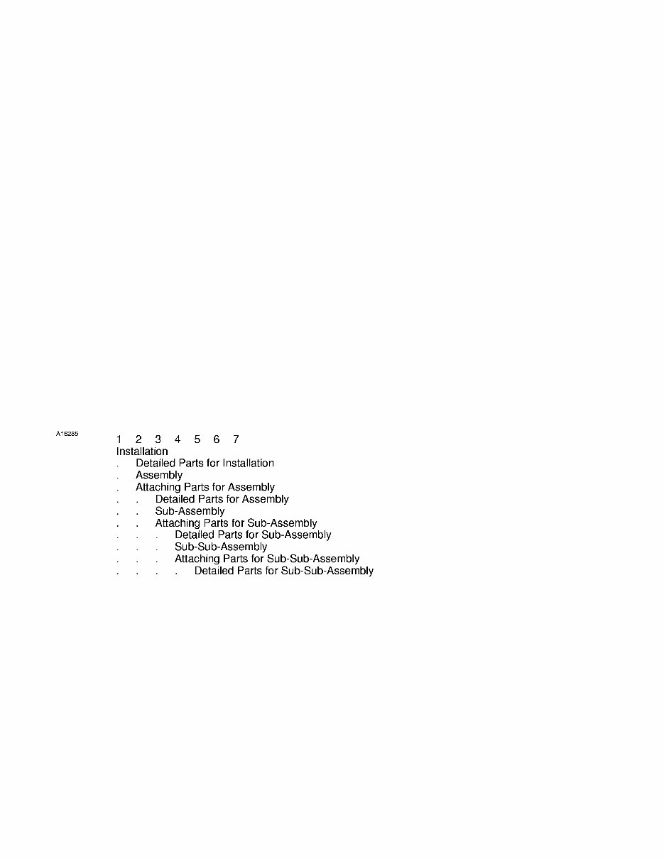
6. Nomenclature Column
A. The indentation system used in the detailed parts list of this catalog shows the relationship of one part
to another. For a given item, the indentation code shows a system, installation or general heading
starting in the extreme left position continuing on down into succeeding columns until the end detail
is reached. (Refer to Figure 1)
Order of Assembly
Figure 1
B. The relationship of the items listed is shown by the degree of indention of each item. For example: the
battery installation is listed in the first indenture of the nomenclature column. The Battery Assembly
Manifold is the next lower assembly and is therefore listed in the second indenture of nomenclature
column. Refer to paragraph A, General System of Assembly Order.
C. If two or more assemblies contain a majority of identical parts or if the assemblies are left or right, the
assemblies are together and the next lower assemblies or detail parts are listed as common for both
assemblies with the differing parts coded for usage on the correct assembly.
D. Attaching parts are listed immediately beneath the item to be attached and preceding any detail parts
of the item. They are listed in the same indention as the item they attach and are preceded by the
caption, Attaching Parts. The end of the attaching parts listing is followed by a separating symbol
INTRODUCTION Page 2
© Cessna Aircraft Company May 1/2008
CESSNA AIRCRAFT COMPANY
MODEL 414
ILLUSTRATED PARTS CATALOG
"---*---". Component parts which are not included in any assembly but are used in conjunction with,
or which attach to certain assemblies, are listed either preceding the first detail or following the last
detail of the assembly or installation and in the same indenture as the major assembly or installation.
7. List of Effective Pages (Paper Version)
A. A List of Effective Pages in front of each chapter of the Illustrated Parts Catalog shows all pages within
the chapter in sequence, with the most recent revision date for each page. A revised List of Effective
Pages is included for every Illustrated Parts Catalog revision.
8. Revision Filing Instructions (Paper Version)
A. Regular Revision
(1) Refer to the List of Effective Pages of each chapter when you insert a revision.
(2) With the revision date given for each page in the List of Effective Pages by chapter, you know
what pages are changed by the applicable revision. For each applicable page, replace the
current page with the revised page.
(3) Remove and discard current pages in the publication that are shown as "Deleted" in the List of
Effective Pages. Each page that is deleted by a revision is not shown in the List of Effective
Pages for subsequent revisions of the publication.
B. Temporary Revision
(1) File pages of a Temporary Revisions in the applicable chapter in accordance with the filing
instructions on the first page of the Temporary Revision.
(2) Remove the Temporary Revisions from the publication only when it is replaced by a revision
to the publication or by instructions in a temporary revision that follows and supersedes this
temporary revision.
9. Revision Indicators
A. Additions, deletions or revisions to the parts list will be identified by the letter "R" in the right margin
of the page adjacent to the change, or addition. When technical changes cause unchanged text to
appear on a different page/pages, an "R" will be placed in the margin opposite of the affected items.
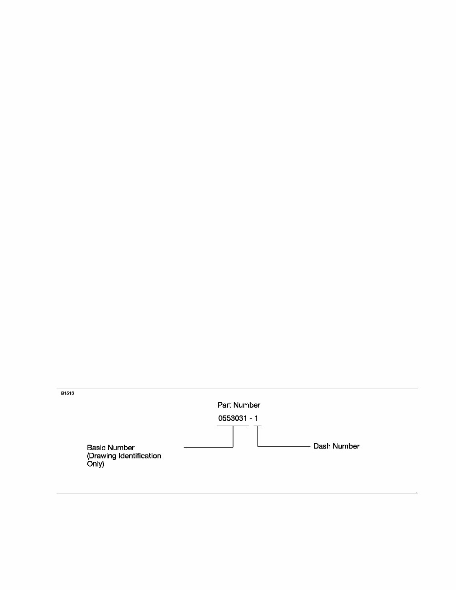
10. Cessna Part Numbering System
A. The basic number identifies the Cessna drawing only. Each Installation, Assembly or Detail Part
is assigned a part number which consists of the drawing number and an appropriate dash number.
(Refer to Figure 2)
EXAMPLE:
Part Number System
Figure 2
INTRODUCTION Page 3
© Cessna Aircraft Company May 1/2008
CESSNA AIRCRAFT COMPANY
MODEL 414
ILLUSTRATED PARTS CATALOG
11. Standard Parts
A. Many parts having standard usage have been incorporated into the Cessna Standard System. Parts
in this group are designated with the part number prefix "S", "CM" or "C".
B. For standard hardware items such as screws, nuts, clamps, etc., AN, NAS, and MS standard numbers
are listed.
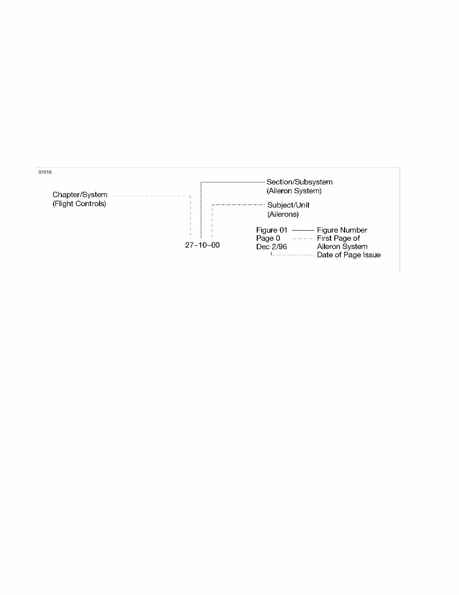
12. Page Numbering System
A. The Page Numbering System used in the Illustrated Parts Catalog consists of the Section Number
and Page Number separated by a dash with the Change Number at the side. (Refer to Figure 3)
Page Numbering System
Figure 3
13. Part Number Column
A. This column contains the part number used to identify the item.
14. Units per Assembly Column
A. The quantity listed in the Units Per Assembly column is the quantity used per figure. The quantity
listed for attaching parts denotes the quantity necessary to attach only one item. The total quantity
necessary to attach more than one item may be obtained by multiplying the quantity of attaching parts
by the number of items to be attached.
15. Symbols and Part Number Terms
A. When the term, REFER TO, appears in the Nomenclature column and the Units Per Assembly column
indicate RF, the figure referred to will be the next higher assembly of the referred item.
B. When the term, DELETED-NOT USED, appears in the Nomenclature column, it signifies that the
index number was used but is no longer required. This procedure is used to eliminate re-indexing of
all items that following the deleted part.
C. When the letters BKI (Bulk Item), appears in the Nomenclature column and the Units Per Assembly
column indicates AR (as required), refer to Cessna Citation Parts Price List for prices and units of
measure.
16. Abbreviations Commonly Used
ALT Alternate IPC Illustrated parts catalog
AR As required NP Non-procurable
ASSY Assembly RF Reference
INTRODUCTION Page 4
© Cessna Aircraft Company May 1/2008

CESSNA AIRCRAFT COMPANY
MODEL 414
ILLUSTRATED PARTS CATALOG
BKI Bulk item SB Service bulletin
FSO For spares order TR Temporary revision
FIG Figure WEU When exhausted use
17. Serial, Color
A. Be sure to indicate model and serial number of the airplane. Serial number is very important to properly
identify parts used on each airplane.
B. When color, upholstery material, Royalite or interior trim are involved, include the complete finish and
trim plate number. See the Finish and Trim Plate information for an example of the numbers to be
supplied. Part numbers, used to identify these parts, are not complete without the finish and trim
numbers.
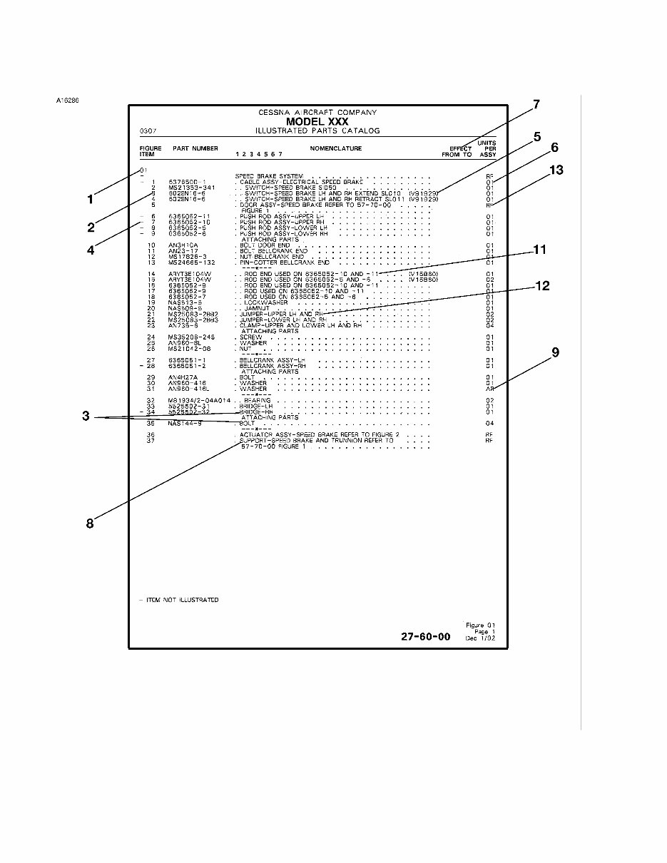
18. Definition of Text Page Information
A. Refer to Figure 4.
(1) The figure number refers to the corresponding illustration.
(2) The number in the Figure and Item Number column corresponds to the item number on the part
in the applicable illustration.
(3) Attaching parts are listed immediately following the part(s) attached. A symbol ---*--- follows the
last item of the attaching parts.
(4) Parts with the item number preceded by a dash are not indexed on the illustration.
(5) A supplier's part number is identified in the part number column, The federally-supplied vendor
code follows the nomenclature in the nomenclature column.
(6) A number in the Units Per Assembly column indicates the quantity of the part used per next
higher assembly or installation.
(7) Numbers in the Effectivity column indicate that usage of the part is restricted. For example, the
numbers 0001 0023 indicate that the part is used on airplanes 1 thru 23.
(8) This cross-reference indicates the figure in which the installation of an assembly is broken down
to its component parts.
(9) Parts with the quantity "as required" are indicated by "AR" in the Units Per Assembly column.
(10) Alternate part numbers are listed immediately after the part for which they can be substituted.
The entry ALT FOR will be shown in the Nomenclature column.
(11) A USED ON or USED WITH note in the nomenclature column indicates the next correct higher
assembly of a part when the part is not common to all of the next higher assemblies listed and
immediately preceding the part.
(12) Parts used only on a left or right installation or assembly are designated by LH or RH in the
Nomenclature column.
(13) "RF" indicates the installation or assembly is listed again in the figure cross-reference in the
Nomenclature column. The Units Per Assembly is given in the referenced figure.
(14) The letter "R" in the right margin indicates that text is added or revised in the latest catalog
revision.
INTRODUCTION Page 5
© Cessna Aircraft Company May 1/2008
CESSNA AIRCRAFT COMPANY
MODEL 414
ILLUSTRATED PARTS CATALOG
PARTS LIST
Figure 4
INTRODUCTION Page 6
© Cessna Aircraft Company May 1/2008
You're Reading a Preview
What's Included?
Fast Download Speeds
Online & Offline Access
Access PDF Contents & Bookmarks
Full Search Facility
Print one or all pages of your manual
$85.99
Viewed 33 Times Today


Secure transaction
What's Included?
Fast Download Speeds
Online & Offline Access
Access PDF Contents & Bookmarks
Full Search Facility
Print one or all pages of your manual
$85.99
The CESSNA Illustrated Parts Catalog is a valuable resource for anyone working on 1969 thru 1985 MODEL 414 AND 414A CHANCELLOR aircraft. This manual, with the current revision P656-4-12, provides detailed diagrams and part numbers essential for maintenance and repairs. Whether you are a professional mechanic or a DIY enthusiast, this manual is an indispensable tool for ensuring the proper upkeep of these aircraft.


