

Cessna 208 Caravan Avionics Service & Parts Manual Install
What's Included?
Fast Download Speeds
Online & Offline Access
Access PDF Contents & Bookmarks
Full Search Facility
Print one or all pages of your manual
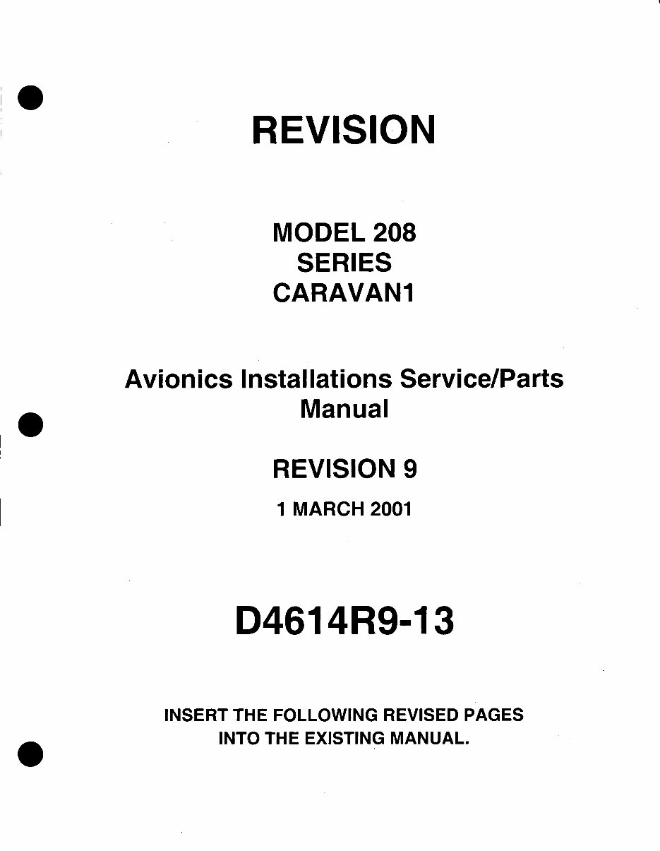
REVISION
MODEL 208
SERIES
CARAVAN1
Avionics Installations Service/Parts
Manual
REVISION 9
1 MARCH 2001
D4614R9-13
INSERT THE FOLLOWING REVISED PAGES
INTO THE EXISTING MANUAL.
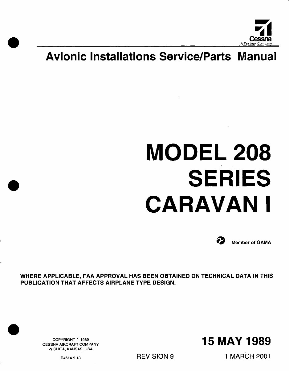
Cessna
A Textron Company
Avionic Installations Service/Parts Manual
MODEL 208
SERIES
CARAVAN I
Member of GAMA
WHERE APPLICABLE, FAA APPROVAL HAS BEEN OBTAINED ON TECHNICAL DATA IN THIS
PUBLICATION THAT AFFECTS AIRPLANE TYPE DESIGN.
COPYRIGHT
®
1989
CESSNA AIRCRAFT COMPANY
WICHITA, KANSAS, USA
15 MAY 1989
1 MARCH 2001 REVISION 9
D4614-9-13
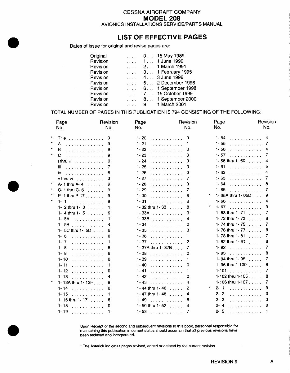
CESSNA AIRCRAFT COMPANY
MODEL 208
AVIONICS INSTALLATIONS SERVICE/PARTS MANUAL
LIST OF EFFECTIVE PAGES
Dates of issue for original and revise pages are:
Original
Revision
Revision
Revision
Revision
Revision
Revision
Revision
Revision
Revision
TOTAL NUMBER OF PAGES IN
Page
No.
Revision
No.
.... 0. 15 May 1989
... 1. 1 June 1990
.... 2. 1 March 1991
.... 3. 1 February 1995
.... 4.. 3 June 1996
.... 5. 2 December 1996
.... 6. 1 September 1998
.... 7. 15 October 1999
.... 8. 1 September 2000
.... 9 1 March 2001
THIS PUBLICATION IS 794 CONSISTING OF THE FOLLOWING:
Page
No.
Revision
No.
Page
No.
Revision
No.
* Title .............
* A ..............
* B ..............
* C . . . .. . . . . .. . . .
i thru ii ...........
iii ..............
iv ..............
v thru vi ..........
* A- 1 thru A-4 ......
* C-1 thru C- 6 ......
* P- 1 thru P-17.......
* 1- 1 . . .. . . . . .. . .
1- 2 thru 1- 3 ......
1- 4thru 1- 5 ......
1- 5A ...........
1- 5B ............
1- 5Cthru 1- 5D ....
1- 6 ............
1- 7 . . . . . . . .. .. .
1- 8 ............
1- 9 ............
1-10 ............
1- 11 . . .. . . . . .. . .
1-12 ............
1-13 ............
* 1-13A thru1-13H . ..
1-14 ............
1-15 ............
1- 16 thru 1- 17 .....
1-18 ............
1-19 ............
1-20 ............
1-21 ............
1-22 ............
1-23 ............
1-24 ............
1-25 ............
1-26 ............
1-27 ............
1-28 ............
1-29 ............
1-30 ............
1-31 ............
1- 32 thru 1- 33 ......
1-33A ...........
1-33B ...........
1-34 ............
1-35 ............
1-36 ............
1-37 .. .. .....
1- 37A thru 1-37B ...
1-38 ............
1-39 ............
1-40 ............
1-41 ............
1-42 ............
1-43 ............
1- 44 thru 1-46 ......
1- 47 thru 1- 48 ......
1-49 ............
1- 50 thru 1- 52 ......
1-53 ............
1-54 ............
1-55 ............
1-56 ............
1-57 ............
1-58 thru 1- 60 ......
1-61 ............
1-62 ............
1-63 ............
1-64 ............
1-65 ............
* 1-65Athru 1-65D ...
1-66 ............
* 1-67 ............
1-68 thru 1-71 ......
1- 72 thru 1- 73 . ....
1-74 thru 1-75 ......
1-76 thru 1-77 ......
1-78 thru 1-81 ......
1-82 thru 1-91 ......
1-92 ............
1-93 ...........
1- 94 thru 1- 95 ......
1- 96 thru 1-100 .....
1-101 ............
1-102 thru 1-105 .....
1-106 thru 1-107 .....
* 2- 1 ... ... ... ...
2- 2 ............
2- 3 ............
2- 4 ............
2- 5 ............
Upon Reciept of the second and subsequent revisions to this book, personnel responsible for
maintaining this publication in current status should ascertain that all previous revisions have
been recieved and incorporated.
* The Asterick indicates pages revised, added or deleted by the current revision.
REVISION 9 A
CESSNA AIRCRAFT COMPANY
MODEL 208
AVIONICS INSTALLATIONS SERVICE/PARTS MANUAL
LIST OF EFFECTIVE PAGES
Page Revision
No. No.
2- 6 ............ 0
2- 7 ............ 3
2- 8 ............ 0
2- 9 ............ 3
2-10 ............ 0
2- 11 ............ 1
2-12 ............ 0
2-13 ............ 1
2-14 ............ 0
2-15 ............ 4
2-16 ............ 0
2-17 ............ 1
2- 17Athru 2- 17B .... 3
2-18 ............ 0
2-19 ............ 1
2-20 ............ 0
2- 21 thru 2- 22 ...... 1
2- 23 thru 2- 24 ...... 2
2- 25 thru 2- 28 ...... 4
2-29 ............ 5
2-30 ............ 4
2-31 ............ 5
2- 32 thru 2- 37 ...... 7
2- 38 thru 2- 43 ...... 8
2- 44 thru 2- 45 ...... 7
2- 46 thru 2- 49 ...... 8
* 3- 1 ............ 9
3- 2 ............ 0
3- 3 ............ 1
3- 4 ............ 0
3- 5 ............ 3
3- 6 ............ 0
3- 7 ............ 3
3- 8 ............ 1
3- 9 ............ 4
3-10 ............ 0
3-11 ............ 1
3-12 ............ 0
* 3-13 ............ 9
3- 14 thru 3- 18 ...... 3
3-19 ............ 4
3- 20 thru 3- 23 ...... 7
3- 24 thru 3- 27 ...... 8
3- 28 thru 3- 29 ...... 7
* 4- 1 ............ 9
Page Revision
No. No.
4- 2 ............ 0
4- 3 .. ... ....... 1
4- 4 ............ 0
4- 5 ............ 1
4- 6thru4- 8 ...... 0
4-9 .......... 1
4-10 .......... 0
4-11 . ......... 1
4-12 .......... 0
4-13 ........ .... 1
4-14 ............ 0
4-15 ............ 1
4-16 ............ 0
4-17 ............ 1
4-18 ............ 0
4-19 ............ 1
4-20 ............ 0
4-21 .......... 1
4-22 .......... 0
4-23 .......... 1
4-24 .......... 0
4-25 ............ 1
4-26 ............ 0
4-27 ............ 1
4-28 ............ 0
4-29 ............ 1
4-30 .... ...... 0
4-31 ............ 1
4-32 ............ 0
4-33 ............ 1
4-34 ............ 0
4-35 ............ 1
4-36 ............ 0
4-37 ............ 1
4- 38 thru 4- 40 ...... 0
4-41 ............ 1
4-42 ............ 0
4-43 .......... 8
4-44 .......... 1
* 4-45 ............ 9
4-46 ............ 8
* 4-47 . ......... 9
4-48 .......... 1
* 4-49 ............ 9
4- 50 thru 4- 51 ...... 7
Page Revision
No. No.
4-52 ............ 0
4-53 ............ 3
4-54 ............ 1
4-55 . ......... 4
4-56 ............ 8
4-57 ............ 7
4- 57A ........... 8
* 4- 57B ........... 9
4- 58 thru 4- 59 ...... 8
4-60 ............ 1
* 4- 61 ............ 9
4-62 ............ 1
4-63 ............ 4
4-64 ............ 7
* 4-65 ............ 9
4-66 ............ 4
* 4-67 ............ 9
4- 68 thru 4- 69 ...... 7
* 5- 1 ............ 9
5-2 ............ 2
5- 3 ...... ...... 3
5- 3A ........... 2
5- 3B ............ 4
5- 4 ............ 2
5- 5thru 5- 7 ...... 4
5- 8 ........... 3
5- 9 ............ 4
* 6- 1 ............ 9
6- 2 ............ 0
6- 3 ............ 1
6- 4 ............ 0
6- 5 thru 6- 5A ..... 4
6- 5B ............ 8
6- 6 ............ 6
6- 7 ............ 7
6- 8thru6- 9 ...... 6
6-10 ............ 0
6- 11 .. ........ .. 1
6-12 ............ 0
6-13 ............ 1
6-14 ........... 5
* 6-15 ........... 9
6-16 ............ 5
6-17 thru 6-23 ...... 6
6- 24 thru 6- 26 ...... 7
Upon Reciept of the second and subsequent revisions to this book, personnel responsible for
maintaining this publication in current status should ascertain that all previous revisions have
been recieved and incorporated.
* The Asterick indicates pages revised, added or deleted by the current revision.
REVISION 9 B
CESSNA AIRCRAFT COMPANY
MODEL 208
AVIONICS INSTALLATIONS SERVICE/PARTS MANUAL
LIST OF EFFECTIVE PAGES
Page Revision Page Revision Page Revision
No. No. No. No. No. No.
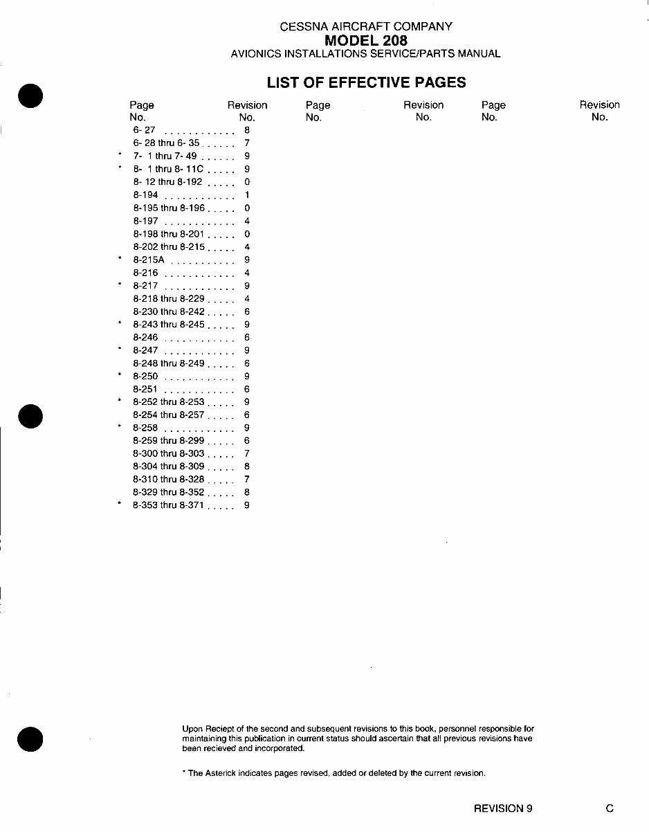
6-27 ............ 8
6- 28 thru 6- 35 ...... 7
* 7- 1 thru 7- 49 ...... 9
* 8- 1thru8-11C ..... 9
8- 12 thru 8-192 ..... 0
8-194 ............ 1
8-195 thru 8-196 ..... 0
8-197 ............ 4
8-198 thru 8-201 ..... 0
8-202 thru 8-215 .... 4
* 8-215A ........... 9
8-216 ............ 4
* 8-217 ............ 9
8-218 thru 8-229 ..... 4
8-230 thru 8-242 ..... 6
* 8-243 thru 8-245 ..... 9
8-246 ............ 6
* 8-247 ............ 9
8-248 thru 8-249 ..... 6
* 8-250 ............ 9
8-251 ............ 6
* 8-252 thru 8-253 ..... 9
8-254 thru 8-257 ... 6
* 8-258 ............ 9
8-259 thru 8-299 ..... 6
8-300 thru 8-303 ..... 7
8-304 thru 8-309 .. 8
8-310 thru 8-328 ..... 7
8-329 thru 8-352 ... 8
* 8-353 thru 8-371 ..... 9
Upon Reciept of the second and subsequent revisions to this book, personnel responsible for
maintaining this publication in current status should ascertain that all previous revisions have
been recieved and incorporated.
* The Asterick indicates pages revised, added or deleted by the current revision.
REVISION 9 C
AVIONIC INSTALLATIONS SERVICE/PARTS MANUAL
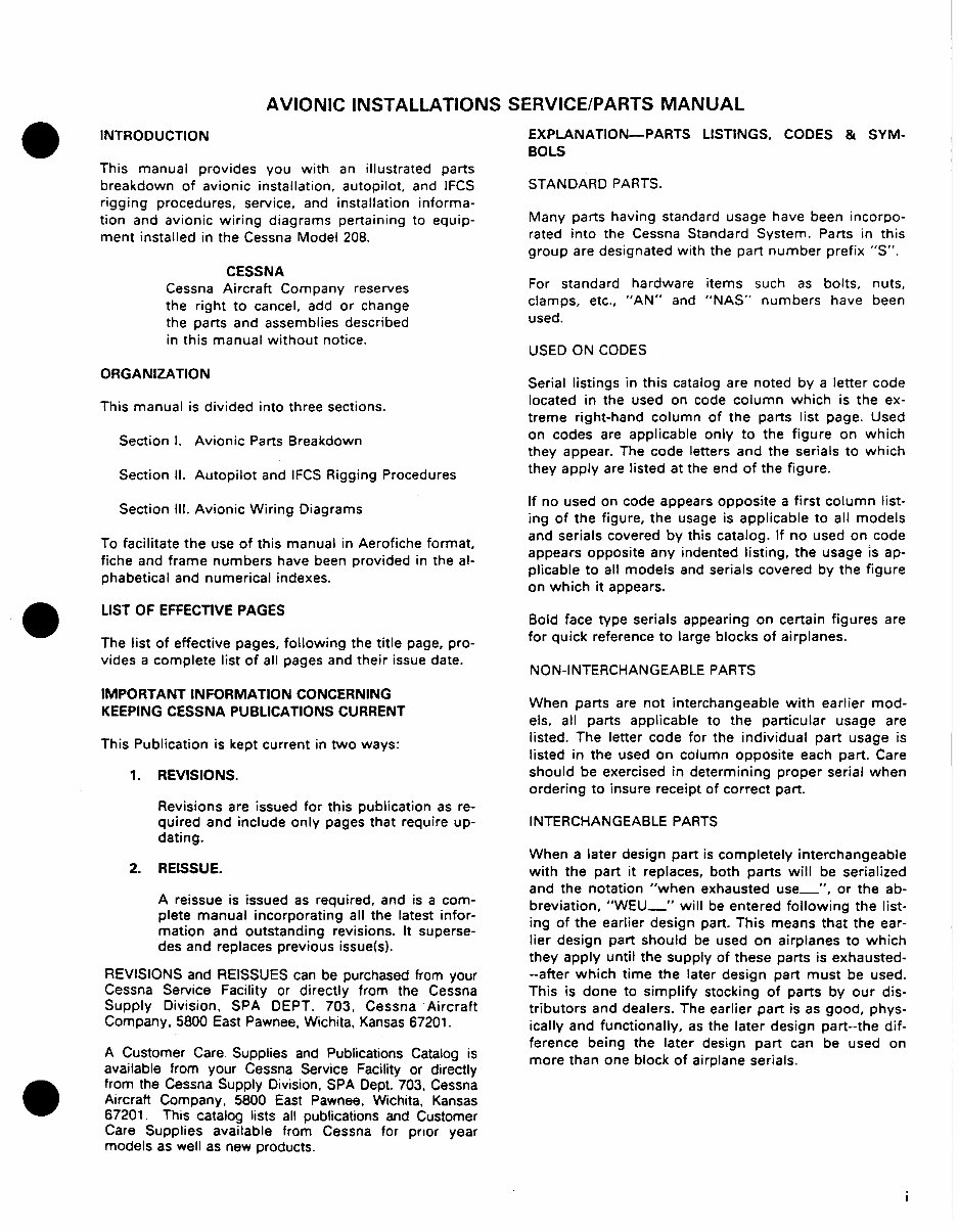
INTRODUCTION
This manual provides you with an illustrated parts
breakdown of avionic installation, autopilot, and IFCS
rigging procedures, service, and installation informa-
tion and avionic wiring diagrams pertaining to equip-
ment installed in the Cessna Model 208.
CESSNA
Cessna Aircraft Company reserves
the right to cancel, add or change
the parts and assemblies described
in this manual without notice.
ORGANIZATION
This manual is divided into three sections.
Section I. Avionic Parts Breakdown
Section II. Autopilot and IFCS Rigging Procedures
Section III. Avionic Wiring Diagrams
To facilitate the use of this manual in Aerofiche format,
fiche and frame numbers have been provided in the al-
phabetical and numerical indexes.
LIST OF EFFECTIVE PAGES
The list of effective pages, following the title page, pro-
vides a complete list of all pages and their issue date.
IMPORTANT INFORMATION CONCERNING
KEEPING CESSNA PUBLICATIONS CURRENT
This Publication is kept current in two ways:
1. REVISIONS.
Revisions are issued for this publication as re-
quired and include only pages that require up-
dating.
2. REISSUE.
A reissue is issued as required, and is a com-
plete manual incorporating all the latest infor-
mation and outstanding revisions. It superse-
des and replaces previous issue(s).
REVISIONS and REISSUES can be purchased from your
Cessna Service Facility or directly from the Cessna
Supply Division, SPA DEPT. 703, Cessna Aircraft
Company, 5800 East Pawnee, Wichita, Kansas 67201.
A Customer Care Supplies and Publications Catalog is
available from your Cessna Service Facility or directly
from the Cessna Supply Division, SPA Dept. 703, Cessna
Aircraft Company. 5800 East Pawnee, Wichita, Kansas
67201. This catalog lists all publications and Customer
Care Supplies available from Cessna for prior year
models as well as new products.
EXPLANATION-PARTS LISTINGS, CODES & SYM-
BOLS
STANDARD PARTS.
Many parts having standard usage have been incorpo-
rated into the Cessna Standard System. Parts in this
group are designated with the part number prefix "S".
For standard hardware items such as bolts, nuts,
clamps, etc., "AN" and "NAS" numbers have been
used.
USED ON CODES
Serial listings in this catalog are noted by a letter code
located in the used on code column which is the ex-
treme right-hand column of the parts list page. Used
on codes are applicable only to the figure on which
they appear. The code letters and the serials to which
they apply are listed at the end of the figure.
If no used on code appears opposite a first column list-
ing of the figure, the usage is applicable to all models
and serials covered by this catalog. If no used on code
appears opposite any indented listing, the usage is ap-
plicable to all models and serials covered by the figure
on which it appears.
Bold face type serials appearing on certain figures are
for quick reference to large blocks of airplanes.
NON-INTERCHANGEABLE PARTS
When parts are not interchangeable with earlier mod-
els, all parts applicable to the particular usage are
listed. The letter code for the individual part usage is
listed in the used on column opposite each part. Care
should be exercised in determining proper serial when
ordering to insure receipt of correct part.
INTERCHANGEABLE PARTS
When a later design part is completely interchangeable
with the part it replaces, both parts will be serialized
and the notation "when exhausted use-", or the ab-
breviation, "WEU_" will be entered following the list-
ing of the earlier design part. This means that the ear-
lier design part should be used on airplanes to which
they apply until the supply of these parts is exhausted-
-- after which time the later design part must be used.
This is done to simplify stocking of parts by our dis-
tributors and dealers. The earlier part is as good, phys-
ically and functionally, as the later design part--the dif-
ference being the later design part can be used on
more than one block of airplane serials.
AVIONIC INSTALLATIONS SERVICE/PARTS MANUAL
SYMBOLS & PART NUMBER TERMS.
NP - The symbol "NP" appearing in the units per as-
sembly column denotes that the item it appears oppo-
site is not procurable.
AR - The symbol "AR" appearing in the units per as-
sembly column denotes "As Required" and is used to
indicate bulk quantity where an indefinite amount is
used.
The following is a list of abbreviations that may ap-
pear in the description nomenclatures:
A/P - Autopilot
ACFT - Aircraft
ADF - Automatic Direction Finder
ALT - Alternate Part
ANT - Antenna
ARC - Automatic Radial Centering
ASSY - Assembly
BC - Backcourse
BCN - Beacon
BKI - Bulk Item
CKT BKR - Circuit Breaker
COM - Communications
DG - Directional Gyro
DIM - Dimming
DISC - Disconnect
DME - Distance Measuring Equipment
ELEC - Electric
ELT - Emergency Locating Beacon
FSO - For Spares Only
FWD - Forward
HF - High Frequency
HI - High
HOZ - Horizon
HSI - Horizontal Situation Indicator
IFCS - Integrated Flight Control System
ILS - Instrument Landing System
IND - Indicator
INST - Instrument
LH - Left Hand
LO - Low
LOC - Localizer
LTS - Lights
MF - Medium Frequency
MKR - Marker
MOD - Modification
MTG - Mounting
NAV - Navigation
OMNI - A Navigational System which Emits Signals
For Each Degree of the Compass Allowing Aircraft
to Determine Their Positions Relative to the
Location of the Transmitter.
OPT - Optional
POT - Potentiometer
PNL - Panel
RCVR - Receiver
REQD - Required
RF - Radio Frequency
RH - Right Hand
RN - Area Navigation
RNAV - Area Navigation
SPKR - Speaker
STD - Standard
UHF - Ultra High Frequency
UPR - Upper
VHF - Very High Frequency
VOL - Volume
VOR - Very High Frequency Omnidirectional Range
WEU - When Exhausted use
XCVR - Transceiver
XMTR - Transmitter
XPDR - Transponder
Other key letter symbols spaced apart from and follow-
ing the part nomenclature are for cataloging and man-
ufacturing purposes only and are not to be considered
by the customer.
A blank entry in the part number column appears be-
fore an unprocurable part or installation which is also
denoted in the "Units Per Assembly" column by the
use of the symbol NP.
GROUP ASSEMBLY PARTS LIST ARRANGEMENT.
All replaceable items in the airplane are detailed on il-
lustrations throughout the manual. The index numbers
on the illustration are keyed to each accompanying
parts list. The purpose of the index numbers is to pro-
vide complete and positive identification of the article,
but should not be used for procurement purposes.
a. The Chapter/Figure & Index number column of
the parts list shows the chapter & figure
number once at the beginning of the list. The
figure number is followed by a dash and the in-
dexed number. The remaining index numbers
are preceded by dash only.
b. The part number column identifies the item by
part number.
c. In the description column, relationship of items
covered is shown by the degree of indention of
each item, for example: The Accessory Unit As-
sembly (Figure 4-11) is listed in column (2) of
the description column. The Circuit Board As-
sembly is a next lower assembly and is there-
fore listed in column (3).
d. If two or more assemblies contain a majority of
identical parts or the assemblies are left or right
hand, the assemblies are listed together and the
next lower assemblies or detail parts are listed
as common for both assemblies, with the differ-
ing parts coded for usage on the correct major
assembly.
ii
CESSNA AIRCRAFT COMPANY
MODEL 208
AVIONIC INSTALLATIONS SERVICE/PARTS MANUAL
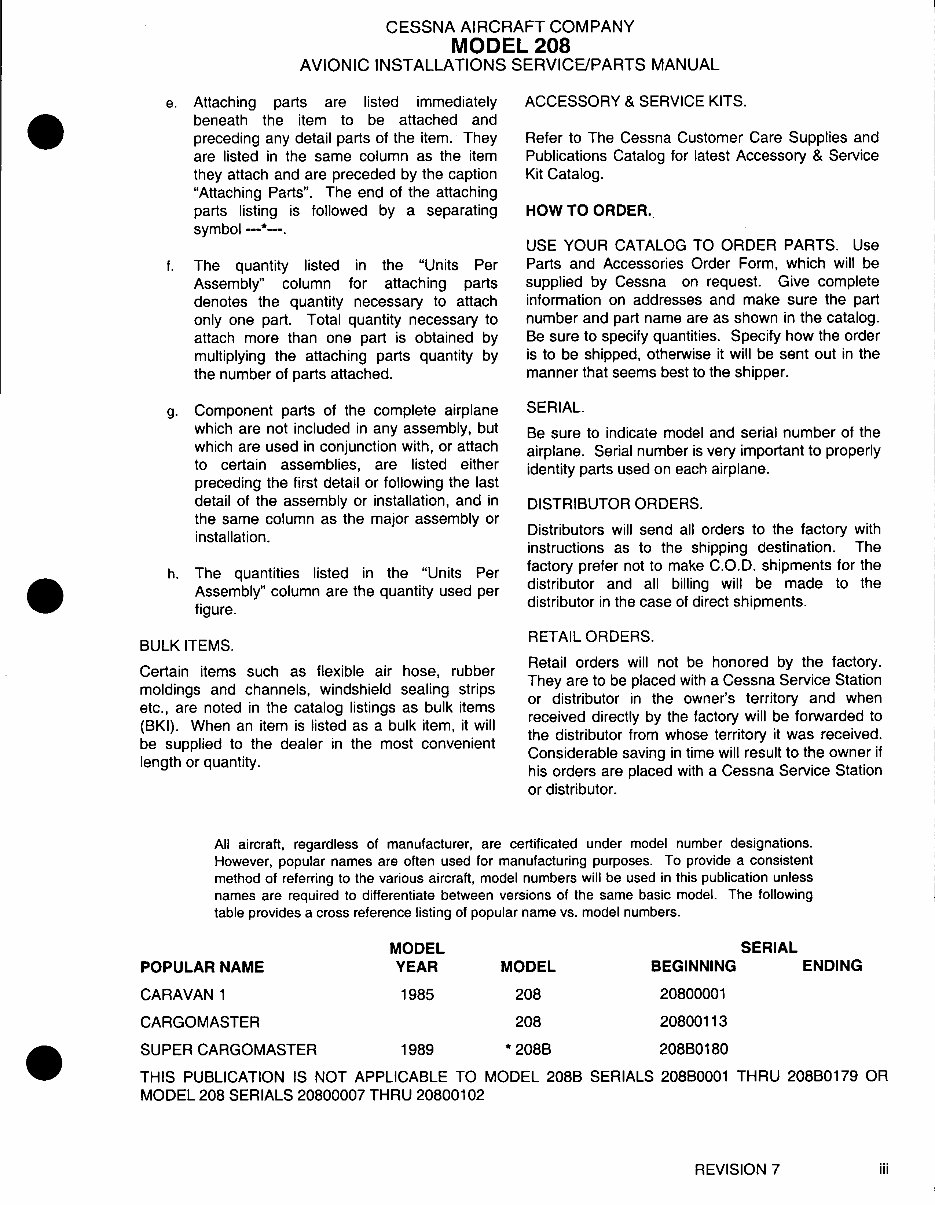
e. Attaching parts are listed immediately
beneath the item to be attached and
preceding any detail parts of the item. They
are listed in the same column as the item
they attach and are preceded by the caption
"Attaching Parts". The end of the attaching
parts listing is followed by a separating
symbol ---*--.
f. The quantity listed in the "Units Per
Assembly" column for attaching parts
denotes the quantity necessary to attach
only one part. Total quantity necessary to
attach more than one part is obtained by
multiplying the attaching parts quantity by
the number of parts attached.
g. Component parts of the complete airplane
which are not included in any assembly, but
which are used in conjunction with, or attach
to certain assemblies, are listed either
preceding the first detail or following the last
detail of the assembly or installation, and in
the same column as the major assembly or
installation.
h. The quantities listed in the "Units Per
Assembly" column are the quantity used per
figure.
BULK ITEMS.
Certain items such as flexible air hose, rubber
moldings and channels, windshield sealing strips
etc., are noted in the catalog listings as bulk items
(BKI). When an item is listed as a bulk item, it will
be supplied to the dealer in the most convenient
length or quantity.
ACCESSORY & SERVICE KITS.
Refer to The Cessna Customer Care Supplies and
Publications Catalog for latest Accessory & Service
Kit Catalog.
HOW TO ORDER.
USE YOUR CATALOG TO ORDER PARTS. Use
Parts and Accessories Order Form, which will be
supplied by Cessna on request. Give complete
information on addresses and make sure the part
number and part name are as shown in the catalog.
Be sure to specify quantities. Specify how the order
is to be shipped, otherwise it will be sent out in the
manner that seems best to the shipper.
SERIAL.
Be sure to indicate model and serial number of the
airplane. Serial number is very important to properly
identity parts used on each airplane.
DISTRIBUTOR ORDERS.
Distributors will send all orders to the factory with
instructions as to the shipping destination. The
factory prefer not to make C.O.D. shipments for the
distributor and all billing will be made to the
distributor in the case of direct shipments.
RETAIL ORDERS.
Retail orders will not be honored by the factory.
They are to be placed with a Cessna Service Station
or distributor in the owner's territory and when
received directly by the factory will be forwarded to
the distributor from whose territory it was received.
Considerable saving in time will result to the owner if
his orders are placed with a Cessna Service Station
or distributor.
All aircraft, regardless of manufacturer, are certificated under model number designations.
However, popular names are often used for manufacturing purposes. To provide a consistent
method of referring to the various aircraft, model numbers will be used in this publication unless
names are required to differentiate between versions of the same basic model. The following
table provides a cross reference listing of popular name vs. model numbers.
POPULAR NAME
CARAVAN 1
CARGOMASTER
SUPER CARGOMASTER
MODEL
YEAR
1985
1989
MODEL
208
208
* 208B
SERIAL
BEGINNING
20800001
20800113
208B0180
THIS PUBLICATION IS NOT APPLICABLE TO MODEL 208B SERIALS 208B0001 THRU 208B0179 OR
MODEL 208 SERIALS 20800007 THRU 20800102
REVISION 7 iii
ENDING
CESSNA AIRCRAFT COMPANY
MODEL 208
AVIONIC INSTALLATIONS SERVICE/PARTS MANUAL
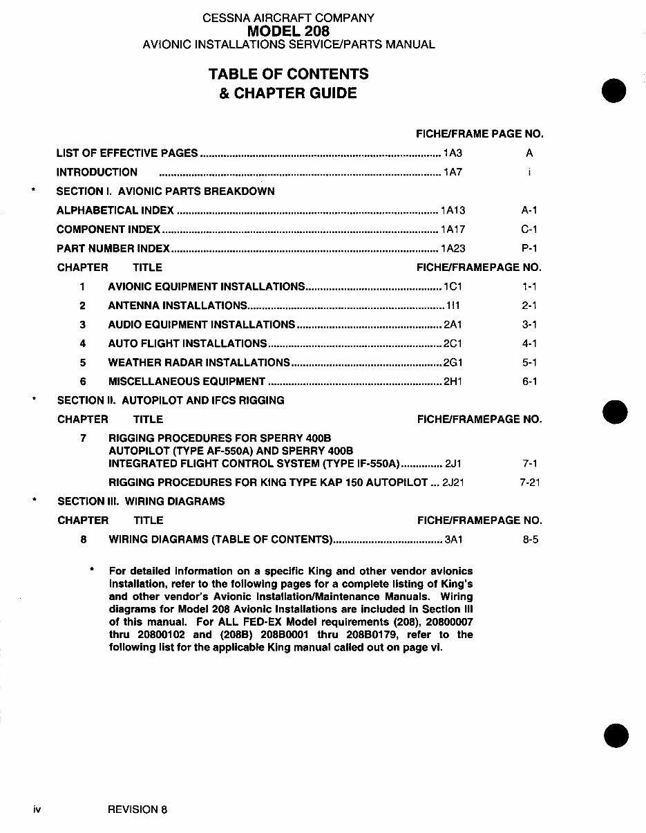
TABLE OF CONTENTS
& CHAPTER GUIDE
FICHE/FR
LIST OF EFFECTIVE PAGES 1 A3
INTRODUCTION 1 A7
SECTION I. AVIONIC PARTS BREAKDOWN
ALPHABETICAL INDEX 1 A13
COMPONENT INDEX 1 A17
PART NUMBER INDEX 1 A23
CHAPTER TITLE FICHE/FR
1 AVIONIC EQUIPMENT INSTALLATIONS 1C1
2 ANTENNA INSTALLATIONS 111
3 AUDIO EQUIPMENT INSTALLATIONS 2A1
4 AUTO FLIGHT INSTALLATIONS 2C1
5 WEATHER RADAR INSTALLATIONS 2G1
6 MISCELLANEOUS EQUIPMENT 2H1
SECTION II. AUTOPILOT AND IFCS RIGGING
CHAPTER TITLE FICHE/FR
7 RIGGING PROCEDURES FOR SPERRY 400B
AUTOPILOT (TYPE AF-550A) AND SPERRY 400B
INTEGRATED FLIGHT CONTROL SYSTEM (TYPE IF-550A) .............. 2J1
RIGGING PROCEDURES FOR KING TYPE KAP 150 AUTOPILOT ... 2J21
SECTION III. WIRING DIAGRAMS
CHAPTER TITLE FICHE/FR
8 WIRING DIAGRAMS (TABLE OF CONTENTS) 3A1
AME PAGE NO.
A
i
A-1
C-1
P-1
AMEPAGE NO.
1-1
2-1
3-1
4-1
5-1
6-1
AMEPAGE NO.
7-1
7-21
AMEPAGE NO.
8-5
* For detailed information on a specific King and other vendor avionics
installation, refer to the following pages for a complete listing of King's
and other vendor's Avionic Installation/Maintenance Manuals. Wiring
diagrams for Model 208 Avionic Installations are included in Section III
of this manual. For ALL FED-EX Model requirements (208), 20800007
thru 20800102 and (208B) 208B0001 thru 208B0179, refer to the
following list for the applicable King manual called out on page vi.
iv REVISION 8
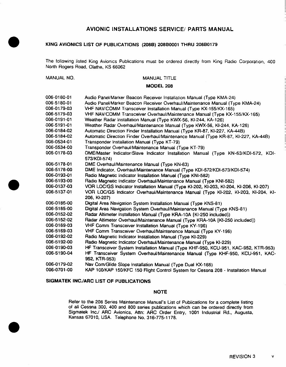
AVIONIC INSTALLATIONS SERVICE/ PARTS MANUAL
KING AVIONICS LIST OF PUBLICATIONS (208B) 208B0001 THRU 208B0179
The following listed King Avionics Publications must be ordered directly from King Radio Corporation, 400
North Rogers Road, Olathe, KS 66062
MANUAL NO.
006-0180-01
006-5180-01
006-0179-03
006-5179-03
006-0191-01
006-5191-01
006-0184-02
006-5184-02
006-0534-01
006-5534-00
006-0178-03
006-5178-01
006-5178-00
006-0193-01
006-5193-00
006-0137-03
006-5137-01
006-0185-00
006-5185-00
006-0152-02
006-5152-02
006-0169-03
006-5169-03
006-0192-02
006-5192-00
006-0190-03
006-5190-04
006-0179-02
006-0701-00
MANUAL TITLE
MODEL 208
Audio Panel/Marker Beacon Receiver Installation Manual (Type KMA-24)
Audio Panel/Marker Beacon Receiver Overhaul/Maintenance Manual (Type KMA-24)
VHF NAV/COMM Transceiver Installation Manual (Type KX-155/KX-165)
VHF NAV/COMM Transceiver Overhaul/Maintenance Manual (Type KX-155/KX-165)
Weather Radar Installation Manual (Type KWX-56, KI-244, KA-126)
Weather Radar Overhaul/Maintenance Manual (Type KWX-56, KI-244, KA-126)
Automatic Direction Finder Installation Manual (Type KR-87, KI-227, KA-44B)
Automatic Direction Finder Overhaul/Maintenance Manual (Type KR-87, KI-227, KA-44B)
Transponder Installation Manual (Type KT-79)
Transponder Overhaul/Maintenance Manual (Type KT-79)
DME/Master Indicator/Slave Indicator Installation Manual (Type KN-63/KDI-572, KDI-
573/KDI-574)
DME Overhaul/Maintenance Manual (Type KN-63)
DME Indicator, Overhaul/Maintenance Manual (Type KDI-572/KDI-573/KDI-574)
Radio Magnetic Indicator Installation Manual (Type KNI-582)
Radio Magnetic Indicator Overhaul/Maintenance Manual (Type KNI-582)
VOR LOC/GS Indicator Installation Manual (Type KI-202, KI-203, KI-204, KI-206, KI-207)
VOR LOC/GS Indicator Overhaul/Maintenance Manual (Type KI-202, KI-203, KI-204, Kl-
206, KI-207)
Digital Area Navigation System Installation Manual (Type KNS-81)
Digital Area Navigation System Overhaul/Maintenance Manual (Type KNS-81)
Radar Altimeter Installation Manual (Type KRA-10A [KI-250 included])
Radar Altimeter Overhaul/Maintenance Manual (Type KRA-10A [KI-250 included])
VHF Comm Transceiver Installation Manual (Type KY-196)
VHF Comm Transceiver Overhaul/Maintenance Manual (Type KY-196)
Radio Magnetic Indicator Installation Manual (Type KI-229)
Radio Magnetic Indicator Overhaul/Maintenance Manual (Type KI-229)
HF Transceiver System Installation Manual (Type KHF-950, KCU-951, KAC-952, KTR-953)
HF Transceiver System Overhaul/Maintenance Manual (Type KHF-950, KCU-951, KAC-
952, KTR-953)
Nav Com/Glide Slope Installation Manual (Type Dual KX-165)
KAP 100/KAP 150/KFC 150 Flight Control System for Cessna 208 - Installation Manual
SIGMATEK INCJARC LIST OF PUBLICATIONS
NOTE
Refer to the 208 Series Maintenance Manual's List of Publications for a complete listing
of all Cessna 300, 400 and 800 series publications which can be ordered directly from
Sigmatek Inc./ ARC Avionics, Attn: ARC Order Entry, 1001 Industrial Rd., Augusta,
Kansas 67010, USA. Telephone No. 316-775-1178.
REVISION 3 v
You're Reading a Preview
What's Included?
Fast Download Speeds
Online & Offline Access
Access PDF Contents & Bookmarks
Full Search Facility
Print one or all pages of your manual
$89.99
Viewed 67 Times Today


Secure transaction
What's Included?
Fast Download Speeds
Online & Offline Access
Access PDF Contents & Bookmarks
Full Search Facility
Print one or all pages of your manual
$89.99
This manual is a comprehensive guide for avionic installations and services for the Model 208 Series Caravan I, dated 15 May 1989 with Revision 9 as of 1 March 2001. It consists of 788 pages that are bookmarked and indexed for easy navigation.
- List of Effective Pages
- Chapter Guide
- Section I. Avionic Parts Breakdown
- Alphabetical Index
- Component Index
- Part Number Index
- Chapter Title Fiche/FR
- 1. Avionic Equipment Installations (1C1)
- 2. Antenna Installations (111)
- 3. Audio Equipment Installations (2A1)
- 4. Auto Flight Installations (2C1)
- 5. Weather Radar Installations (2G1)
- 6. Miscellaneous Equipment (2H1)
- Section II. Autopilot and IFCS Rigging
- 7. Rigging Procedures for Sperry 400B Autopilot (Type AF-550A) and Sperry 400B Integrated Flight Control System (Type IF-550A) (2J1)
- 8. Rigging Procedures for King Type KAP 150 Autopilot (2J21)
- Section III. Wiring Diagrams
- 9. Wiring Diagrams (Table of Contents) (3A1)
For detailed information on specific avionics installations from King and other vendors, please refer to the complete listing of their Avionic Installation/Maintenance Manuals. The wiring diagrams for Model 208 Avionic Installations are included in Section III of this manual. For all FED-EX Model requirements (208), 20800007 thru 20800102 and (208B) 208B0001 thru 208B0179, please refer to the applicable King manual called out on page vi.


